MtP400 Series Operator’s Manual Printek, Inc. 1517 Townline Road Benton Harbor, MI 49022 269-925-3200 www.printek.com Printek Part Number 5885 Rev.
FCC Part 15 Class B This device complies with Part 15 of the RCC Rules. Operation is subject to the following two conditions: (1) this device may not cause harmful interference, and (2) this device must accept any interference received, including interference that may cause undesired operation. This equipment has been tested and found to comply with the limits for a Class B digital device, pursuant to Part 15 of the FCC rules.
Read all setup and operating instructions before proceeding with operation. Do not operate in an enclosure unless properly ventilated. Make sure no ventilation openings are blocked or obstructed, which may result in the printer overheating. Do not operate near a heat source. Lesen Sie vor der Inbetriebnahme die Aufbau- und Bedienungsanleitung. Betreiben Sie den Drucker nicht in einem kleinen, geschlossenen Raum, es sei denn dieser wird ordnungsgemäß belüftet.
TABLE OF CONTENTS Introduction ..........................................................................................................................................................1 Getting Started .....................................................................................................................................................3 Battery Installation and Charging .....................................................................................................................
Table of Contents Maintenance and Troubleshooting....................................................................................................................37 Cleaning..........................................................................................................................................................37 Battery Care ....................................................................................................................................................
Introduction Thank you for purchasing a Printek MtP400 Series Mobile Thermal Printer. The MtP400 series offer a variety of configurations to suit any printing environment. The MtP400 series consists of three basic models for receipt and label printing. The standard MtP400 prints on receipt paper supplied in roll form up to 4.2 inches wide. The MtP400 SL model prints on receipt paper up to 4” wide and 6” long supplied in easy to load cassettes containing 100 sheets each.
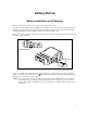
Getting Started Battery Installation and Charging Note: You must charge the battery for at least 2½ hours prior to the first use. The battery for your MtP400 printer is shipped in an “uncharged” state. The battery must be charged using the following instructions prior to using the printer for the first time. Maximum battery capacity is not reached until after completing a minimum of three complete charge and discharge cycles.
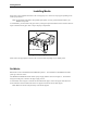
Getting Started Installing Media Each printer comes supplied with either a roll of receipt paper or a cassette of receipt paper depending on the model you purchased. Note: For maximum performance and optimum print quality, use only genuine Printek media in your MtP400 series printer. To install media, you must release the paper door by moving the Paper Door Release in the direction shown in Figure 2 and then lift the paper door to expose the paper compartment.
Getting Started Movable Support Figure 3 - Media Support Refer to Figure 4 and unroll enough paper to allow it to lay through the print head as shown, and close the paper door. Figure 4 - Paper Laying Through Print Head You may now press the Paper Feed Button to advance the paper a few inches and then tear it off in preparation for printing. Cassette Media The MtP400 SL models use cassettes containing 100 sheets of receipt paper.
Getting Started Insert the cassette into the printer as shown in Figure 5. Make sure that the smooth side of the cassette with the Printek logo down and the flap side up, and close the paper door. Figure 5 - Cassette In Printer Turning the Printer On and Off To turn the printer on, simply press the Power Button. If you continue to hold the Power Button, the printer will display the printer’s model number.
Getting Started Host Interface Set Up Prior to using your printer with a computer application, check the interface settings to be sure they match those required by your host system. Each printer is equipped with a Serial RS-232C interface which is selected by default. Additionally, the printer may also be equipped with either an IrDA interface, Bluetooth interface, or Wi-Fi interface. The model description on the serial number label will indicate if one of the optional interfaces is installed.
Getting Started Belt Loop System The belt loop system consists of two parts – a knob located on the bottom of the printer and a belt loop strap with a click on connector To use the belt loop system, slide your belt through the strap of the belt loop and then insert the knob located on the bottom of the printer into the slot of the belt loop connector. Pull down on the printer until you hear a click. The printer is now secure and can safely hang down beside your hip.
Daily Operation Introduction For normal daily use, most users will only need to turn the printer on and off, load paper, and recharge the battery at the end of the day. The following sections describe these simple activities and provide additional information regarding the use of the MtP400. Control Panel The MtP400 series printers are designed for simple operation with an easy to use control panel. As shown in Figure 6, the control panel consists of an LCD Display, five indicators, and four pushbuttons.
Daily Operation Enter Button – Used in printer configuration menus to advance to the next setup feature. May also be used to print the settings and connection information for the currently selected interface. Power Indicator – ON indicates that the power is on and that the printer is in normal power mode. SLOW FLASH indicates that the printer is in Setup mode and not accepting data.
Daily Operation Figure 7 - Tearing Off Printed Output MtP400 SL Models The MtP400 SL models use cassettes of cut sheet receipt paper. In most cases, the host application program will issue a Form Feed that will eject the sheet currently being printed so that it is ready for the user to simply pull out of the printer. If the sheet has not been ejected and the host has finished sending data to the printer, the paper may be ejected by pressing the Paper Feed Button.
Daily Operation Power Connector Battery Indicator Figure 8 - MtP400 Power Connector & Battery Indicator When the power supply is connected, the printer’s charging circuitry will determine if the battery currently requires charging and if so, will turn on the Battery Indicator until the battery has reached sufficient charge. Depending on the condition of the battery, charging may take up to 2½ hours to complete.
Daily Operation If the card is read successfully, a short beep will sound, “Card Read Ok” will be displayed and the MCR Indicator will stop flashing and remain on briefly to indicate success as the data is sent to the host system. If the card is not read successfully, a longer error tone will sound, “Card Not Read” will be displayed and the Error Indicator will also begin to flash.
Printer Configuration Introduction To Setup The MtP400 series printers feature an easy to use control panel “Setup” menu system for setting permanent configuration parameters. These menus offer many useful and necessary features, but are typically only used when first setting up the printer. They are rarely used in normal everyday operation. The values that are set are used as the “defaults” whenever the printer is turned on or reset by the host system.
Printer Configuration Entering Setup To enter Setup, press and hold the Enter Button while turning on the printer with the Power Button. Continue to hold the Enter Button until “Menus Active” appears on the LCD Display. After releasing the Enter Button, “Entering Setup Menus” will be displayed momentarily before advancing to the “FORMAT MENU”. While in Setup Mode, the power indicator will blink slowly.
Printer Configuration Setup Menu Summary Format Menu Interface Menu Format n Serial IrDA Emulation Printek*, O’Neil, ZPL-II, Mt3, CPCL, Hex Dump Emulation Emulation Printek*, Printek*, O’Neil, O’Neil, ZPL-II, Mt3, ZPL-II, CPCL, Hex Dump Mt3, Pairing Mode CPCL, Hex Dump Paired*, Unpaired Format Name Up to 16 Characters Font 4.2, 5.5, 10.2, 10.7, 18.5, 20.3 SansSerifA; 12.7, 13.5, 14.5, 15.6, 16.9*, 18.5, 20.3, 22.6, 25.
Printer Configuration The bottom line of the display shows the Format that is currently selected. If you wish to change to a different format, press the Increment Button until the desired Format is displayed. Note: If you wish to use more than one Format, you must first enable additional Formats. Please refer to the “Max Format” feature in the “Options Menu” on page 29.
Printer Configuration Spacing Spacing 3 Lines Possible Values: 0 … 3* … 10 Lines When printing text, this feature sets spacing between lines. The height of a complete line, or line pitch, is determined by adding the vertical size of the current font to the Spacing. With Spacing set to the default value of “3” and using a font that is 23 rows high, the line pitch would be 3 + 23, or 26 dot rows. Since each dot row is 0.125mm, 26 x 0.125 yields a line pitch of 3.25mm. or 7.
Printer Configuration Print Contrast Print Contrast 0 Possible Values: -75 … 0* … +125 in increments of 5 The printer automatically adjusts the amount energy used in order to maintain constant print quality as the battery discharges during use. The Print Contrast setting modifies the value that is determined to be needed by the printer and may be used to obtain improved print quality on different qualities of thermal print media.
Printer Configuration Mark Sensitivity Mark Sensitivity 0 Possible Values: -10 …0* …+10 This feature allows the Black Mark/Paper Fault sensor to be adjusted to allow for variations in media materials and Black Mark printing methods. The following list will help determine if, and how, the Mark Sensitivity should be adjusted. • • • If the printer is not detecting black marks reliably, set the Mark Sensitivity to a lower value.
Printer Configuration Serial Interface INTERFACE MENU Serial Note that “Serial” must be displayed on the bottom line of the display in order to access the following features and for this interface to be active when Setup is exited. Emulation Emulation Printek Possible Values: Printek*, O’Neil, ZPL-II, Mt3, CPCL, Hex Dump This feature sets the family of printer commands that may be used by a host application program to control the various capabilities of the printer.
Printer Configuration Parity Parity None Possible Values: None*, Even, Odd This feature sets the parity checking requirements for the data bits in the serial character frame. The value must match the setting used on the host system. XON/XOFF Handshaking XON/XOFF Off Possible Values: Off*, On This feature enables or disables the XON/XOFF (DC1/DC3) character handshaking method used to control data flow from the host system to the printer.
Printer Configuration IrDA Interface INTERFACE MENU IrDA Note that “IrDA” must be displayed on the bottom line of the display in order to access the following features and for this interface to be active when Setup is exited. Emulation Emulation Printek Possible Values: Printek*, O’Neil, ZPL-II, Mt3, CPCL, Hex Dump This feature sets the family of printer commands that may be used by a host application program to control the various capabilities of the printer.
Printer Configuration Pairing Mode Pairing Mode Paired Possible Values: Paired*, Unpaired This feature allows Bluetooth pairing to occur between the printer and the connecting device whenever Security is required by either device. Pairing requires that the PIN on the printer and the connecting exactly match each other. PIN PIN 0 Possible Values: 0*, Up to 16 Numeric Characters. Note that this feature is only available if Paring Mode is set to Paired.
Printer Configuration Address Address 0080371B8F32 Possible Values: Twelve digit hexadecimal string. This feature displays the unique hardware value associated with the particular Bluetooth interface installed in the printer. This value is set by the hardware manufacturer, is guaranteed to be unique for each interface, and may not be changed.
Printer Configuration WLAN Channel WLAN Channel 1 Possible Values: 1* … 14 Note that this feature is only available if the WLAN Type is set to Peer-to-Peer. This feature sets the radio channel to be used when communicating in a Peer-to-Peer network. When in an Infrastructure network, the radio channel is automatically assigned by the interface and Access Point.
Printer Configuration WLAN Auth WLAN Auth Auto Possible Values: Auto*, Open, Shared This feature specifies the authentication method that will be used when establishing connections on the network. The method may be to use an open key or a shared key. If set to “Auto”, the printer will automatically match itself to the method used by other nodes.
Printer Configuration Tunnel Port Number Tunnel Port# 08023 Possible Values: 00000 … 08023* … 65384 This feature specifies the TCP/IP port to be used for data that is to be printed.. To advance through the character positions, press the position, press the Increment Button. Advance Button. To change the character at the current Note: This feature is available in printers with firmware revision 2.0 and higher.
Printer Configuration Auto Power Down Auto Power Down Off Possible Values: Off*, 1 Minute Delay … 15 Minute Delay This feature sets whether the printer will automatically power down and if so, after what period of time of inactivity. If set to a value other that “Off”, the printer will automatically turn itself off after the specified number of minutes have passed since the printer last received data or last printed, whichever is longer.
Interfacing To A Host Computer Every MtP400 is equipped with an RS-232C Serial Interface. Optional factory installed interfaces are also available for IrDA (Infrared), Bluetooth®, and Wi-Fi®. When the printer is equipped with one of the optional interfaces, the interface that is selected in the Interface Menu as described on page 21 is the one that will be active and the other interface will be ignored.
Interfacing to a Host Computer IrDA Interface In addition to the standard Serial interface, your MtP400 may be equipped with an optional IrDA interface. IrDA interfaces are commonly found on many PDA’s and notebook computers. To communicate using the IrDA interface, “IrDA” must be selected in the Interface Menu as described on page 24. The IrDA interface uses infrared light to provide a cable free, short range interface.
Interfacing to a Host Computer When discovered, the default name that will appear will be “MtP400-xxxx” where “xxxx” is the last four digits of the Bluetooth interface’s hardware Address. To obtain the printer’s Bluetooth name, you may use the printer’s Setup menus or you may have the printer print it out. To print all the configuration for the interface, press and hold the Enter Button until “Printing Setup” is displayed.
Power Considerations MtP400 printers are designed to provide superior output using as little power as necessary. This provides the longest possible battery life. The printers may also be operated from an external power supply when used in a more permanent installation in a vehicle or office. The following discussions indicate how the printer accomplishes this power conservation using features such as Standby and Auto Power Down.
Maintenance and Troubleshooting Cleaning In normal environments, the printer should be cleaned after printing a few rolls of paper or if there are voids in the printout. For optimum performance and life, you should clean the Print Head and Platen Roller whenever you load new paper. If your printer is an MtP400 SL model, you should also clean the Pick Roller.
Maintenance and Troubleshooting Battery Care Charging the Battery The printer’s battery is charged in the printer using an optional power supply. Power supplies are available for 100-240VAC/50-60Hz and for 12/24VDC vehicle applications. Follow the steps listed below to charge the battery. An optional external two-bay charger is also available. • Plug the power supply into a power source appropriate for the adapter being used. • Plug the power supply into the power connector on the side of the printer.
Maintenance and Troubleshooting Testing the Power Supply and Battery To verify that the printer’s internal battery charger is functioning properly, perform the following steps. • Test the power adapter (100-240VAC/50-60Hz, 12/24VDC adapter) with a voltmeter to verify that its output voltage is 9 VDC. • Connect the power supply to a power source and then connect it to the printer. • Verify that the printer’s Battery Indicator is illuminated. If illuminated, the charging circuit is functioning properly.
Maintenance and Troubleshooting Troubleshooting When encountering problems, the cause may be the printer or may sometimes be due to other problems with your system. Please review the following tables to solve common problems you may encounter with your printer. You may also visit www.printek.com for additional “FAQ’s” that may assist you. If you are still unable to solve your problem, please contact the company where you purchased your printer since they are most familiar with your systems.
Maintenance and Troubleshooting Other Problems Problem Printer will not turn on. Possible Cause Battery not installed properly. Printer turns itself off. Discharged battery. Auto Power Down is enabled. Battery discharged. Electrostatic discharge. Battery Indicator does not light or does not stay lit when power supply is connected. Battery already fully charged. Power supply not receiving power. Faulty power supply. Battery not installed properly. Battery not charging. Faulty power supply or battery.
Maintenance and Troubleshooting Obtaining Service If service is required for your printer, please contact the company where you purchased your printer. If they are unable to assist you, contact Printek Customer Service at (800) 368-4636 to obtain the name of the nearest Printek Authorized Service Center. If you wish to return your printer to Printek for service, please contact Printek Customer Service at (800) 3684636 to obtain a Return Authorization Number.
Advanced Setup Features An additional security menu is available for system administrators who prefer to “lock out” operator changes to the various menus. This method of security can be set independently for the Format Menu, the Interface Menu, or the Options Menu. When set to Edit Allowed, the user is allowed to make changes to any item in the menu specified. When set to View, the operator can review the settings, but cannot edit, or change, the values.
Print & Font Samples Print Samples 45
Print & Font Samples Courier Font With International Extended Character Set Courier Font PC Line Drawing Extended Character Set 46
Print & Font Samples Sans Serif Font 47
Specifications Printer Specifications Printing Specifications Printing Method: Printing Resolution: Printing Width: Direct Thermal, Up To 3.3 Inches Per Second 203 dots per inch (8 dots per mm) 832 Printing Elements for up to 4.1″ (10.
Specifications Physical Specifications Size: Weight: MtP400 & MtP400 LP – 8.1 x 6.6 x 3.1 inches, 19.56 x 16.76 x 7.87 cm (LxWxH) MtP400 SL – 9.6 x 6.6 x 2.0 inches, 19.56 x 16.76 x 5.08 cm (LxWxH) 2.2 lbs. (1.
Specifications Media Specifications Receipt Paper General Specifications: MtP400, MtP400 LP: (Roll Media) MtP400 SL: (Preloaded Cassette) Approved Vendors: 0.0022 to 0.0065” (0.056 to 0.089mm) Thick Black Mark Sensing On Printed Side (Black Mark Sensing On Back Side and Gap Sensing On MtP400 LP Models) 3 to 4.125” (76.2 to 104.78mm)Wide 0.750” (19.05mm) Inside Diameter Core 2.625” (66.68mm) Maximum Outside Diameter 3 to 4” (76.2 to 101.
Specifications Black Mark Position The vertical position of a Black Mark is dependent on the application program that will be used to search for and print relative to the mark. The following diagram shows the optimum position when seeking the Black Mark at the beginning of a print job and will require little, if any, reverse paper motion. (Note that reverse paper motion in MtP400 SL models is not supported.) The Black Mark must be printed on the front side of the paper for the MtP400 and MtP400 SL models.
Specifications Supplies and Accessories Supplies Battery: 7.4V, 2200 mAH Li-Ion Available separately or in 5 or 20 packs. Receipt Paper – Rolls: 4.125” Width * Available in cases of 36. Receipt Paper – Cassettes: 4” Wide x 6” Long * Available in cases of 36 cassettes of 100 pages each. Labels – Rolls: 4 x 6”, 4 x 4”, or 4 x 3” * Available in cases of 36. * Other sizes available on request.
Glossary of Terms 802.11 Wireless networking communication standards created by IEEE. access point An interface between a wireless network and a wired network. Ad-Hoc A Wi-Fi network consisting of only stations (no access point). Same as Peerto-Peer. ASCII American Standard Code for Information Interchange. authentication The process a Wi-Fi station uses to identify itself to another station. bandwidth The amount of data that be transferred in a given period of time.
Glossary IP Internet Protocol. A specification for packets, or datagrams, of data and an addressing method to allow the exchange of data with another system. Must be combined with another protocol such as TCP to create a complete connection with the other system. LAN Local Area Network. LCD Liquid crystal display. LED Light emitting diode. line pitch The vertical spacing of rows of characters. Measured in lpi. lpi Lines per inch.