Cover Zebra® ZXP Series 8™ Card Printer with Laminator User’s Manual P1013372-001 Rev.
Copyright Notice © 2010 ZIH Corp. This document contains information proprietary to Zebra Technologies Corporation. This document and the information contained within is Copyrighted by Zebra Technologies Corporation and may not be duplicated in full or in part by any person without written approval from Zebra.
Contents 1 • Introduction . . . . . . . . . . . . . . . . . . . . . . . . . . . . . . . . . . . . . . . . . . . . . . . 1 Components . . . . . . . . . . . . . . . . . . . . . . . . . . . . . . . . . . . . . . . . . . . . . . . . . . . 2 Controls, Connectors, and Indicators . . . . . . . . . . . . . . . . . . . . . . . . . . . . . . . . 5 Icons . . . . . . . . . . . . . . . . . . . . . . . . . . . . . . . . . . . . . . . . . . . . . . . . . . . . . . . . . 6 Zebra Supplies . . . . . . . . . . . . . . . . .
Contents 4 • Printer Settings and Adjustments . . . . . . . . . . . . . . . . . . . . . . . . . . . . 63 Introduction . . . . . . . . . . . . . . . . . . . . . . . . . . . . . . . . . . . . . . . . . . . . . . . . . . . 63 Card Printer Properties . . . . . . . . . . . . . . . . . . . . . . . . . . . . . . . . . . . . . . . . . . 64 Card Printer Printing Preferences . . . . . . . . . . . . . . . . . . . . . . . . . . . . . . . . . . 72 5 • ZXP Series Toolbox. . . . . . . . . . . . . . . . . . . . . . . . .
1 Introduction This manual contains installation and operation information for the Zebra P810i & P820i Card Printer manufactured by Zebra Technologies Corporation. Zebra ZXP Series 8 Card Printers are available without lamination, or with a single- or dualside lamination.
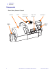
Introduction Components Components Front View, Covers Closed Laminator Printer Printer Cover Release Button Single Card Feed Slot Operator Control Panel Output Hopper 2 Input Hopper Zebra ZXP Series 8 Card Printer with Laminator P1013372-001 Rev.
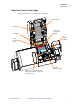
Introduction Components Front View, Printer Cover Open The following figure shows components of the Printer. Transfer Station Transfer Film Printhead (Under Print Ribbon) Print Ribbon Card Cleaning Cartridge Card Cleaning Roller Reject Bin (Under Feed Tray) Mag Encoder and/or Smart Card Options (If Installed); Components Under This Cover P1013372-001 Rev.
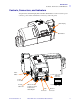
Introduction Components Front View, Laminator Cover Open The following figure shows components of the Laminator. Upper Laminate Cassette Latch (single-sided and dual-sided laminators) Upper Laminate Cassette (single-sided and dual-sided laminators) Heater Output Hopper Enclosure Lock (optional) Manual Advance Tool 4 Lower Laminate Cassette Latch (dual-sided laminator only) Lower Laminate Cassette (dual-sided laminator only) Zebra ZXP Series 8 Card Printer with Laminator P1013372-001 Rev.
Introduction Controls, Connectors, and Indicators Controls, Connectors, and Indicators Your printer has an LCD Display Panel and three Panel Buttons on the front and a power connector, power switch, and interface connector(s) on the rear panel. OCP Display OCP Buttons Power Switch Ethernet Connector Power Connector Security Cable Slot P1013372-001 Rev.
Introduction Icons Icons Throughout this manual, different icons highlight important information, as follows: Note • Indicates information that emphasizes or supplements important points of the main text. Important • Advises you of information that is essential to complete a task, or points out the importance of specific information in the text. Provides an example or scenario to demonstrate or clarify a section of text.
2 Installation and Setup General Information This section will guide you through the installation and setup of your Card Printer. This consists of the following procedures, which should be performed in the order presented. • Unpacking the Printer. . . . . . . . . . . . . . . . . . . . . . . . . . . . . . . . . . . . . . . . . . . 8 • Installing the Card Hoppers . . . . . . . . . . . . . . . . . . . . . . . . . . . . . . . . . . . . . 10 • Loading Cards . . . . . . . . . . . . . . . . . . . . . . . . .
Installation and Setup Unpacking the Printer Unpacking the Printer Step 1. Inspect the shipping container to ensure that no damage has occurred during shipment. If any damage is apparent, file a claim with the shipper. Step 2. Open the shipping container. Step 3. Remove the packing material and accessories from around the top of the Printer. Important • Save all the packing material and the shipping carton in case the Printer needs to be moved or shipped.
Installation and Setup Unpacking the Printer Caution • The Printer weighs approximately 44 lbs (20 kg); use two people to lift it out of the shipping carton. Step 5. With two people holding the carrying strap (colored blue, green, and red for clarity), carefully lift the Printer out of the recess in the lower foam insert. Step 6. Place the Printer in a location that meets the following requirements: • A reasonably dust- and dirt-free environment.
Installation and Setup Installing the Card Hoppers Installing the Card Hoppers Input Hopper The Input Hopper is positioned on the right side of the Printer and holds the cards to be printed. Step 1. Install the Input Hopper by sliding the hopper into the receptacle on the right side of the Printer. Step 2. Ensure that the Input Hopper locks securely in place. Output Hopper The Output Hopper is positioned on the left side of the Printer and receives the printed cards. Step 1.
Installation and Setup Loading Cards Loading Cards Caution • DO NOT bend cards or touch print surfaces as this can reduce print quality. The surface of the cards must remain clean and dust free. Always store cards in an enclosed container. Ideally, use cards as soon as possible. Step 1. Remove the wrapping from the card deck. Step 2. Holding the card deck by the sides (do not touch the print surfaces), hold it vertically against a flat surface such as a desktop.
Installation and Setup Opening the Printer Door Opening the Printer Door Step 1. Press the Door Release button on the top of the Printer. Step 2. Observe that the Door releases and pops up approximately half an inch. Step 3. Grasp the Door at the bottom front. Step 4. Lift the Door to its upright position. It will remain in that position. 12 Zebra ZXP Series 8 Card Printer with Laminator P1013372-001 Rev.
Installation and Setup Installing the Cleaning Cartridge Installing the Cleaning Cartridge The Cleaning Cartridge cleans the cards entering the Printer from the Input Hopper. The Cleaning Cartridge consists of a Cartridge Frame and an Adhesive Roller, which are packed together. Step 1. Remove the Cartridge Frame and the Adhesive Roller from their packaging. Step 2. Insert the Adhesive Roller into the Cartridge Frame. To avoid contamination, always hold the frame and the roller by the ends. Step 3.
Installation and Setup Installing the Cleaning Roller Installing the Cleaning Roller The Cleaning Roller cleans the cards entering the Printer from either the Input Hopper or the Single-Feed Input. Step 1. Remove the Cleaning Roller from its packaging. To avoid contamination, always hold the roller by the ends. Step 2. Peel the protective wrapper from the Cleaning Roller. Step 3. Open the Printer Door by pressing the Door Release button on the top of the Printer. Step 4.
Installation and Setup Loading the Transfer Film Loading the Transfer Film The ZXP Series 8 printer is designed to work only with Zebra True Colours™ i Series™ Transfer Film for near photographic print resolution and over-the-edge printing. Step 1. Locate the transfer film supply spindles and the transfer film take-up spindles. Note that the Flanges and Spindles are color coded (white-to-white, green-to-green).
Installation and Setup Loading the Transfer Film Step 2. Unroll about one foot from the full roll of transfer film (supply spool), and wind it (2 wraps) onto the empty take-up spool. Step 3. Load transfer film supply spool onto the supply spindles, green flange side to the left. Step 4. Load the empty take-up spool onto the take-up spindles, white flange side to the right. Step 5. Make sure the spring-loaded spindles on the right seat into the spools. Step 6.
Installation and Setup Loading a Print Ribbon Loading a Print Ribbon The ZXP Series 8 printer is designed to work only with Zebra True Colours® i Series™ Ribbons in order to achieve rich, vibrant, image production over the full-color spectrum. Step 1. Locate the print ribbon supply spindles and the print ribbon take-up spindles. Note that the Flanges and Spindles are color coded (blue-to-blue, purple-to-purple).
Installation and Setup Loading a Print Ribbon Step 2. Load the print ribbon supply spool onto the supply spindles, purple flange side to the left. Step 3. Load the empty take-up spool onto the take-up spindle, blue flange side to the right. Step 4. Make sure the spring-loaded spindles on the left seat into the spools. Step 5. Make sure the print ribbon comes off the bottom of the supply spool and feeds to the bottom of the take-up spool. Step 6.
Installation and Setup Loading the Laminate Loading the Laminate Opening the Laminator Door Step 1. Grasp the Door at the bottom front. Step 2. Lift the Door to its upright position. It will remain in that position. Note that the Lower Laminate Cassette is only present on the dual-sided laminator. P1013372-001 Rev.
Installation and Setup Loading the Laminate Removing the Laminate Cassette(s) Step 1. Rotate the locking lever maximum in the direction indicated in the figure below. Step 2. Rotate the cassette to the mechanical stop in the direction indicated below. 20 Zebra ZXP Series 8 Card Printer with Laminator P1013372-001 Rev.
Installation and Setup Loading the Laminate Step 3. Remove the cassette(s) by pulling each cassette straight out from its spindle. Step 4. Open the cassette(s), like a clam shell, by separating its two halves. Grasp the two halves firmly with your fingers, then pull it apart. Do NOT use tools. (Upper Laminate Cassette shown.) Step 5. If there is an empty laminate core in the cassette, remove it. P1013372-001 Rev.
Installation and Setup Loading the Laminate Loading the Laminate Cassette(s) Step 1. Remove the new roll of laminate from its packaging. Important • The geared flange on the laminate spool is removable, but do not remove it. If it does come off, snap it back onto the end of the spool. Step 2. Cut the laminate as shown, as close to perpendicular as possible. 22 Zebra ZXP Series 8 Card Printer with Laminator P1013372-001 Rev.
Installation and Setup Loading the Laminate Step 3. Carefully following the guidelines in the following figure, place the laminate in the cassette. • Upper Laminate Cassette (present on both the single-sided laminator and dualsided laminator): • Lower Laminate Cassette (only present on the dual-sided laminator): Step 4. Pull out an inch or two of laminate past the lip of the cassette. Step 5. Close the cassette by firmly pressing the “clamshell” together.
Installation and Setup Loading the Laminate Step 7. Rotate the core to adjust the laminate overhang. Stop when the end of the laminate is just beyond the lip of the cassette, as shown below. Important • Check for laminate overhang any time the locking lever is pressed or the cassette is removed. 0 - 0.5 mm 0 - 1/32" 0 - 0.5 mm 0 - 1/32" 24 Zebra ZXP Series 8 Card Printer with Laminator P1013372-001 Rev.
Installation and Setup Loading the Laminate Installing the Laminate Cassette(s) Step 1. Slide the cassette onto the spindle. Step 2. Ensure the cassette is fully seated on the spindle. Gently press the cassette until it is flush against the laminator frame. P1013372-001 Rev.
Installation and Setup Loading the Laminate Step 3. Rotate each cassette (in the direction indicated in the figure below) until it stops. Step 4. Observe the locking lever snap into place. 26 Zebra ZXP Series 8 Card Printer with Laminator P1013372-001 Rev.
Installation and Setup Loading the Laminate Laminating Contact Smart Cards The laminate for the top surface of a contact smart card has a repeating pattern of an index hole and a rectangular cutout to expose the card’s electrical contacts. electrical contacts rectangular cutout index hole Step 1. Remove the Upper Laminate Cassette; see Page 20. Step 2. Open the cassette, and remove the laminate if present. Step 3. Load the smart card laminate into the cassette; see Page 22. Step 4.
Installation and Setup Loading the Laminate Step 5. Rotate the core to adjust the laminate overhang. Stop when the end of the laminate (not the edge of the index hole) is even with the edge of the lips of the cassette. Step 6. Install the cassette; see Page 25. 28 Zebra ZXP Series 8 Card Printer with Laminator P1013372-001 Rev.
Installation and Setup Loading the Laminate Using Partial-Width Laminate Note • Since partial-width laminates are only used for the back (i.e., lower) surface of the card, this section only applies to the dual-sided laminator. Laminates come in three widths: “Full-Width” laminate is 2 in (51 mm) wide. The full-width laminate is used on the front (i.e., upper) or back (i.e., lower) surface of the card. “Partial-Width” laminate is available in two widths: • 1.
Installation and Setup Loading the Laminate Step 1. Remove the Lower Laminate Cassette; see Page 20. Step 2. Open the cassette, and remove the laminate if present. Step 3. Load the partial-width laminate into the cassette. Note that the collar on the laminate spool is on the end opposite the geared flange. Collar Step 4. Trim the partial-width laminate. Step 5. Rotate the core to adjust the laminate overhang. Stop when the end of the laminate is even with the edge of the lips of the cassette. Step 6.
Installation and Setup Connecting Power Connecting Power Electric Shock Caution • Limit AC power supplied to the Printer to 100 – 230 volts, 60 ~ 50 Hertz. Limit excess current draw to 16 amps or less, using an associated circuit breaker or other such device. Never operate the Printer in a location where operator, computer, or printer can get wet. Personal injury could result.
Installation and Setup Connecting the Printer to your Computer Connecting the Printer to your Computer Important • Use either the USB connection or the Ethernet connection but not both at the same time. USB Connection Step 1. Connect the USB cable to the printer and the computer. Step 2. Ensure that the printer’s power switch in the OFF ( ) position. USB 32 Zebra ZXP Series 8 Card Printer with Laminator P1013372-001 Rev.
Installation and Setup Connecting the Printer to your Computer Ethernet Connection Step 1. Connect the Ethernet Port on the rear of the printer to an Ethernet Network Port. Step 2. Turn the printer’s power switch to the ON ( ) position. 10/100base-T 10/100base-T P1013372-001 Rev.
Installation and Setup Installing the Windows Printer Driver Installing the Windows Printer Driver Initial Steps Each computer that will use the printer must have the Printer Driver installed. If not already done, connect power to the printer; and connect the printer to the computer. • For USB Driver installation, turn the printer OFF ( • For Ethernet Driver installation, turn the printer ON ( ). ).
Installation and Setup Installing the Windows Printer Driver Installing the USB Printer Driver Note • To install the Ethernet driver, see Page 40. Step 1. If not already done, connect power to the printer. Do not turn power ON. Step 2. Connect the USB port on the rear of the printer to the computer’s USB port. Step 3. Ensure that the Printer’s power switch is in the OFF ( ) position. Step 4. Insert the User Documentation and Drivers CD into the CD drive of the host computer. The Main Menu will open.
Installation and Setup Installing the Windows Printer Driver Step 9. The InstallShield Wizard window will open. To proceed with the installation, click the Next button. Step 10. Select Install USB printer drivers, and click the Next button. Step 11. Ensure that the Printer’s power switch in the OFF ( OK button. 36 Zebra ZXP Series 8 Card Printer with Laminator ) position; and then click the P1013372-001 Rev.
Installation and Setup Installing the Windows Printer Driver Step 12. This will bring up the License Agreement window. To proceed with the installation, select the I accept the terms of the license agreement option, and then click the Next button. Step 13. This will bring up the Customer Information window. Enter User Name and Company Name; and then click the Next button. P1013372-001 Rev.
Installation and Setup Installing the Windows Printer Driver Step 14. This will bring up the Choose Destination Location window. • To accept the default destination location where setup will install the files, click the Next button. - or - • Select a folder where setup will install the files, and click the Next button. Step 15. This will bring up the Ready to Install the Program window. To continue, click the Install button. Step 16. Observe the Setup Status window.
Installation and Setup Installing the Windows Printer Driver Step 17. The Congratulations window will appear. Step 18. At this point, turn on your printer; and then click the Next button. The Windows New Hardware Found wizard will find the printer. Step 19. When the InstallShield Wizard Complete window appears, select the Yes, I want to restart my computer now radio button; and click the Finish button. Step 20. This completes USB driver installation. Step 21.
Installation and Setup Installing the Windows Printer Driver Installing the Ethernet Printer Driver Note • To install the USB driver, see Page 35. Important • The Ethernet Network must be configured correctly, with the Printer and the host computer on the same subnet mask. Use the printer’s default-configured DHCP address (there must be a DHCP server on the network) or set the Printer to a Static IP address; see Network Settings Menu on page 58.
Installation and Setup Installing the Windows Printer Driver Step 8. In the Welcome window, choose the maintenance operation to be performed: a. Select Modify to upgrade the older printer driver, click the Next button, and follow the screen prompts. At the end of the upgrade process, you will be asked to re-boot your computer. Re-boot your computer. The upgrade is complete. b. Select Remove to remove the older printer driver, click the Next button, and follow the screen prompts.
Installation and Setup Installing the Windows Printer Driver Step 11. Ensure that you have powered ON ( ) the network printer and it is reachable from the PC; and then click the OK button. Step 12. This will bring up the License Agreement window. To proceed with the installation, select the I accept the terms of the license agreement option, and then click the Next button. Step 13. This will bring up the Customer Information window.
Installation and Setup Installing the Windows Printer Driver Step 14. Identify the printer: • Click on the Search button (arrow below) to search for all the Ethernet printers on the network, select the desired printer, and then click the Next button. - or - • Enter the Printer IP Address directly (example circled below), and click the Next button. Step 15. Enter the location of the printer, and add any applicable comments; and then click the Next button. P1013372-001 Rev.
Installation and Setup Installing the Windows Printer Driver Step 16. This will bring up the Choose Destination Location window. • To accept the default destination location where setup will install the files, click the Next button. - or - • Click the Change button, select a folder where setup will install the files, and click the Next button. Step 17. This will bring up the Ready to Install the Program window. To continue, click the Install button. Step 18. Observe the Setup Status window.
Installation and Setup Installing the Windows Printer Driver Step 19. When the InstallShield Wizard Complete window appears, select the Yes, I want to restart my computer now radio button; and click the Finish button. Step 20. This completes Ethernet driver installation. Step 21. To use the Printer, you would select it just like you would any other printer connected to the Ethernet. Note • You may need to change the card setup (card type, orientation, etc.
46 Zebra ZXP Series 8 Card Printer with Laminator P1013372-001 Rev.
3 Operation Introduction Printing with the Card Printer is similar to printing with any other printer in a Windows environment. • The Printer Driver Software is installed on your computer (see Section 2). • The Printer is connected to the power source and the computer (see Section 2). • The Printer is selected by either the Operating System or the appropriate application software program. • Printer Properties are set (the factory default values will be appropriate for many applications).
Operation Card Type Selection Card Type Selection The Card Setup tab allows you to to specify the card type in use. Based on your selection, the printer automatically adjusts various printer properties for optimum print quality. To access the Card Setup Tab, select Start > Printers and Faxes. Right click on the Zebra ZXP Series 8 Card Printer listing; and select Printing Preferences > Card Setup.
Operation Printing a Sample Card Printing a Sample Card Sample card designs are installed with the printer driver. To print a sample card: 1. Access the Card Setup Tab, select Start > Printers and Faxes. Right click on the Zebra ZXP Series 8 Card Printer listing; and select Printing Preferences > Card Setup. 2. Ensure that cards are in the Input Hopper. 3. Click of the Test Print button (circled above). Note • It is normal for the Printer to warm up to operating temperature before printing. 4.
Operation Manual Card Feed Manual Card Feed A Manual Feed Slot is available for feeding single cards. The Input Hopper must be empty for single-card feeding to work properly. 1. Access the Card Setup Tab: Select Start > Printers and Faxes. Right click on the Zebra ZXP Series 8 Card Printer listing; and select Printing Preferences > Card Setup. 2. From the Card Info > Card source dropdown menu, select the Single card feed slot (circled above). 3.
Operation Manual Card Feed 5. Insert a single card into the slot in the correct orientation. Do not feed more than one card at a time. Caution • DO NOT bend cards or touch print surfaces as this can reduce print quality. The surface of the cards must remain clean and dust free. Always store cards in an enclosed container. Ideally, use cards as soon as possible. ✔ P1013372-001 Rev.
Operation Operator Control Panel (OCP) Operator Control Panel (OCP) The printer is equipped with an OCP Display and three OCP Buttons which give access to the printer menus. The menus can be accessed when the printer status shows READY. ZXP Series 8 READY MENU INFO Message CANCEL Button Functions Buttons • Press the MENU button, to access the Main Menu. • Press the INFO button, to access and view the Printer Settings Menu.
Operation Operator Control Panel (OCP) Operational Operational Messages are displayed during the Printer’s normal operation. MESSAGE ALARM CANCELING CONFIG DATA CONTACT OPERATION CONTACTLESS OPERATION COOLING COOLING PRINT JOB WAITING COOLING PRINTHEAD TEMPERATURE COOLING WAITING TO LAMINATE DIAGNOSTIC DESCRIPTION An error message needs to be cleared before normal operations can resume. The Cancel button was pressed, and the current operation is being terminated.
Operation Operator Control Panel (OCP) Warning Messages Warnings alert the operator to action that should be taken; the printer will generally continue operation. WARNING (Printer will still operate) DESCRIPTION BOTTOM LAMINATE LOW Indicates that the Bottom Laminate cassette is low; see Loading the Laminate, Section 2. CLEAN FRONT CARD PATH Indicates that the Front Card Path (Y-Drive Rollers) needs cleaning; see Cleaning the Printer, Section 6.
Operation Operator Control Panel (OCP) Printer Menu Information Info Menu INFO Button (Operating Mode Display) Displays MCB FW Ver, HCB FW Ver, MAB FW Ver, MSN (Machine Serial Number), and PH S/N (Printhead Serial Number) PRINTER INFO Displays DHCP, IP, Mask, GW, and MAC NETWORK INFO RIBBON INFO Displays P/N, Type, # Images, and % Remaining FILM INFO Displays P/N, Type, # Images, and % Remaining Displays Card Count and Printhead Lines PRINTHEAD USAGE Lists RAM, Single or Dual Sided, and Options
Operation Operator Control Panel (OCP) Main Menu MENU Button (Operating Mode Display) RETURN UP 56 PRINT TEST CARDS See Print Test Cards Menu on page 57 NETWORK SETTINGS See Network Settings Menu on page 58 ADVANCED SETTINGS See Advanced Settings Menu on page 59 Main Menu DOWN SELECT • Press the UP button to move up the menu list • Press the DOWN button to move down the menu list • Press the SELECT button to select the item from the list.
Operation Operator Control Panel (OCP) Print Test Cards Menu Main Menu RETURN COUNT Sets the number of Test Cards to be printed (1, 5, 10, ..., 100) SIDES Selects single-sided or double-sided card printing Selects the type of card; e.g., Custom, PVC, PET, PETG, etc. CARD TYPE Mid Gray Grid On Gray Selects Test Card to be printed; see OCP Test Card Images on page 127.
Operation Operator Control Panel (OCP) Network Settings Menu Main Menu RETURN WITHOUT SAVE SAVE SETTINGS Enable or disable the DHCP Mode DHCP MODE SET IP ADDRESS Change the IP Address SET SUBNET MASK Change the Subnet Mask SET DEFAULT GATEWAY UP 58 Change the GW (Gateway) Network Settings Menu DOWN SELECT • Press the UP button to move up the menu list • Press the DOWN button to move down the menu list • Press the SELECT button to select the item from the list.
Operation Operator Control Panel (OCP) Advanced Settings Menu Main Menu RETURN SELECT LANGUAGE Displays current language, sets language option (English, French, Spanish, German, Brazilian Portuguese, or Italian) FLUSH PRINT QUEUE Deletes all pending print jobs in the printer PRINTER ONLINE Toggles printer Online / Offline CLEAN PRINTER See Clean Printer Menu on page 60 Sets sleep timer function value SET SLEEP TIMER SET SCREEN CONTRAST UP Adjusts the OCP display contrast Advanced Settings M
Operation Operator Control Panel (OCP) Clean Printer Menu Advanced Settings Menu RETURN Refer to Section 6, Cleaning, for detailed cleaning instructions CLEAN SIDE CARD PATH Use the X Roller Cleaning Card, and step through the cleaning process CLEAN FRONT CARD PATH Use the Y Roller Cleaning Card, and step through the cleaning process CLEAN HEATER ROLLERS Use the Hot Roller Cleaning Card, and step through the cleaning process CLEAN LAMINATOR Use the Laminator Cleaning Card, and step through the cle
Operation Ethernet Indicators -- Detail Ethernet Indicators -- Detail Ethernet Connector Link/Activity LED Speed LED Link/Activity Indicator (Green) Off No link (disconnected) On Network link has been established Blinking Network activity has been detected Speed Indicator (Orange) P1013372-001 Rev. A Off No link (disconnected) 1 Blink The LED blinks once (one blink, pause, one blink, etc.) when a 10Base link has been established.
62 Zebra ZXP Series 8 Card Printer with Laminator P1013372-001 Rev.
4 Printer Settings and Adjustments Introduction This section describes settings and adjustments that can be made to your Windows ZXP Series 8 Printer Driver. This consists of two major topics: Card Printer Properties . . . . . . . . . . . . . . . . . . . . . . . . . . . . . . . . . . . . . . . . . . . . 64 Card Printer Printing Preferences . . . . . . . . . . . . . . . . . . . . . . . . . . . . . . . . . . . . 72 P1013372-001 Rev.
Printer Settings and Adjustments Card Printer Properties Card Printer Properties To access the Card Printer Properties, select Start > Printers and Faxes. Right click on the Zebra ZXP Series 8 Card Printer listing, then select Properties. 64 • General Tab - Displays printer information of a general nature, includes selection for Printing Preferences and Print Test Page (i.e., the standard Windows test page).
Printer Settings and Adjustments Card Printer Properties General Tab The General tab shows the selected printer and lists the features of the printer. To access the General tab, select Start > Printers and Faxes. Right click on the Zebra ZXP Series 8 Card Printer listing. Select Properties > General. • Location - Lets you specify where the printer is located. • Comment - Lets you specify general information about the printer, such as the type of print device and who is responsible for it.
Printer Settings and Adjustments Card Printer Properties Sharing Tab On the Sharing tab (Sharing Property Page), you can choose to share the printer over the network and install additional drivers to accommodate different operating systems. To access the Sharing tab, select Start > Printers and Faxes. Right click on the Zebra ZXP Series 8 Card Printer listing. Select Properties > Sharing.
Printer Settings and Adjustments Card Printer Properties Ports Tab Use the Ports tab to specify the computer port to which the printer is connected. This will have been established at the initial installation of the printer, and will not normally require attention. To access the Ports tab, select Start > Printers and Faxes. Right click on the Zebra ZXP Series 8 Card Printer listing. Select Properties > Ports.
Printer Settings and Adjustments Card Printer Properties Advanced Tab The Advanced tab determines the spooling (queuing) of print jobs and determines how spooled jobs are handled relative to the most recent job. To access the Advanced tab, select Start > Printers and Faxes. Right click on the Zebra ZXP Series 8 Card Printer listing. Select Properties > Advanced. To enable spooling: Select the radio button labeled Spool print documents so program finishes printing faster.
Printer Settings and Adjustments Card Printer Properties Color Management Tab Important • The optimal color profile is automatically selected when the card type is selected; see the Printing Preferences, Card Setup Tab. Color Management settings allow you to associate color profiles on the printer based on the type of media being used and printer configuration. The Add button allows the operator to add additional profiles to the color profile list.
Printer Settings and Adjustments Card Printer Properties Security Tab This is the standard Windows security screen, showing user access to various printer control options. Both Print and Manage Printers must be checked for full functionality of the printer. To access the Security tab, select Start > Printers and Faxes. Right click on the Zebra ZXP Series 8 Card Printer listing. Select Properties > Security. The Security tab allows you to assign the actual permissions that apply to the print queue.
Printer Settings and Adjustments Card Printer Properties Device Information Tab The Device Information tab provides device information, security status, and printer usage. Access to Media Info and ZXP ToolBox is included. To access the Device Settings tab, select Start > Printers and Faxes. Right click on the Zebra ZXP Series 8 Card Printer listing. Select Properties > Device Information.
Printer Settings and Adjustments Card Printer Printing Preferences Card Printer Printing Preferences To access the Card Printer Printing Preferences, select Start > Printers and Faxes. Right click on the Zebra ZXP Series 8 Card Printer listing; and select Printing Preferences. • Card Setup Tab - Allows user to adjust selected card parameters. • Encoding Tab - Allows the user to set various magnetic encoding options. • Black Panel (K) Tab - Displays available options for Black Extraction.
Printer Settings and Adjustments Card Printer Printing Preferences Card Setup Tab Card Setup tab allows the user to adjust selected card and print job parameters. To access the Card Setup Tab, select Start > Printers and Faxes. Right click on the Zebra ZXP Series 8 Card Printer listing; and select Printing Preferences > Card Setup. • Card Info allows the user to select the Card Source, Card Destination, and Card Type. - Card type in use allows the user to specify the card type in use.
Printer Settings and Adjustments Card Printer Printing Preferences Advanced Black Panel Options Pop-Up The Advanced Black Panel Options pop-up window allows you to manage and configure Black Extraction. This window is available when using Black Panel (K-Panel) ribbons; e.g., YMCK, YMCKK, etc. This window controls how the driver selects the text and/or graphics to be printed with the Black Panel. To access the Advanced Black Panel Options pop-up window, select Start > Printers and Faxes.
Printer Settings and Adjustments Card Printer Printing Preferences • Black extraction from color images: - Print black with K panel: Specify the zones as Defined areas, Undefined areas, or Full card. - Black level: The driver evaluates the RGB values of the card design and looks for an RGB value of 000 in order to determine what should be printed in Black.
Printer Settings and Adjustments Card Printer Printing Preferences Uv Panel Pop-Up A Uv Panel is a resin-based coating similar to a “K” panel and is used to print invisible images (text or graphics) that will glow in the visible spectrum when exposed to a Black Light. The Uv Panel pop-up window allows you to manage and configure printing with a Uv Panel. This window is only available when using Uv ribbons (e.g.
Printer Settings and Adjustments Card Printer Printing Preferences • Uv printing options: Note that Rotate 180o , Grayscale, and Halftone are enabled when Bitmap based Uv varnish (see above) is selected. - Rotate 180o - Grayscale - Halftone • Double pass: Use this option to optimize the quality of the Uv image. This is a two-step process: 1) print and transfer the card without the Uv image, 2) print and transfer the card a second time with the Uv image only, on top of the existing print image.
Printer Settings and Adjustments Card Printer Printing Preferences Inhibit Pop-Up The Inhibit pop-up window allows you to select the inhibit panel area for mag stripe, signature panel, or other non-printing areas of a card. This window is available only when using ribbons with an inhibitor panel; e.g., YMCKi. To access the Inhibit pop-up window, select Start > Printers and Faxes. Right click on the Zebra ZXP Series 8 Card Printer listing, and select Printing Preferences > Card Setup.
Printer Settings and Adjustments Card Printer Printing Preferences Image Control Option The Image Control button brings up the Image Control window, which lets you make color adjustments to compensate for camera or lighting conditions. Keep in mind that these color adjustments modify how the pictures print. The adjustments do not affect the image files. (That type of adjustment would be made in an image processing application program.
Printer Settings and Adjustments Card Printer Printing Preferences Encoding Tab The Encoding screen allows the user to set various magnetic and smart card encoding options. To access the Encoding Tab, select Start > Printers and Faxes. Right click on the Zebra ZXP Series 8 Card Printer listing; and select Printing Preferences > Encoding. Although these options are user-selectable, they are set automatically when the Card Type is selected in the Card Setup Tab on page 73.
Printer Settings and Adjustments Card Printer Printing Preferences Black Panel (K) Tab The Black Panel (K) Tab is used when black resin printing (for text, logos, and/or barcode) is required. To access the Black Panel (K) Tab, select Start > Printers and Faxes. Right click on the Zebra ZXP Series 8 Card Printer listing; and select Printing Preferences > Black Panel (K). Select the appropriate radio button (Text, Barcode, Pictures, or Mixed) for optimized print quality.
Printer Settings and Adjustments Card Printer Printing Preferences About Tab The About Tab shows the copyright and the driver version for the Zebra ZXP Series 8 Card Printer. To access the About Tab, select Start > Printers and Faxes. Right click on the Zebra ZXP Series 8 Card Printer listing; and select Printing Preferences > About. 82 Zebra ZXP Series 8 Card Printer with Laminator P1013372-001 Rev.
5 ZXP Series Toolbox Introduction Important • Use of the ZXP Series Toolbox is intended only for advanced users and system administrators. The ZXP Series Toolbox provides advanced configuration capabilities and tools to manage the operation of your printer. Note that the ZXP Series Toolbox is a separate application that works independently from the printer driver. P1013372-001 Rev.
ZXP Series Toolbox ZXP Series Toolbox Access ZXP Series Toolbox Access To access the ZXP Series Toolbox from the printer driver, select Start > Printers and Faxes. Then right-click on the Zebra ZXP Series 8 Card Printer listing, and select Properties > Device Information > ZXP ToolBox. The ZXP Series Toolbox can also be accessed via Start > All Programs > Zebra ZXP Series 8 Card Printer > ZXP ToolBox. 84 Zebra ZXP Series 8 Card Printer with Laminator P1013372-001 Rev.
ZXP Series Toolbox Information Information Printer This information cannot be edited or changed by the user; however, this information may be useful for Zebra trained and certified personnel in diagnosing or evaluating printer status. • Firmware and Driver lists the versions of the Firmware (Firmware version, HCB, MAB, Laminator, and Laminator MAB) and the version of the Driver. • Other shows the Interface, the Transfer type, and the Card type in use, RAM, Printer serial no, and Laminator serial no.
ZXP Series Toolbox Information Sensors These characteristics cannot be edited or changed by the user; however, this information may be useful for Zebra trained and certified personnel in diagnosing or evaluating printer sensors status. 86 • Sensor States details the state of each printer sensor. • Sensor Values details the value of each printer sensor. • Ribbon Take-up Motor lists various electrical characteristics of the motor. Zebra ZXP Series 8 Card Printer with Laminator P1013372-001 Rev.
ZXP Series Toolbox Information Media This screen displays ribbon, transfer film, and laminate details. This data is automatically read and updated from the installed media in the printer. • Ribbon Details include Type, Description, Zebra part number, Initial size, Images remaining. • Transfer Film Details include Type, Description, Zebra part number, Initial size, Images remaining. • Top Laminate Details include Type, Description, Zebra part number, Initial size, Images remaining.
ZXP Series Toolbox Information Laminator This information cannot be edited or changed by the user; however, this information may be useful for Zebra trained and certified personnel in diagnosing or evaluating laminator status. 88 • Status information includes Warnings and Faults; Communications, AC Power, and Heated Rollers; Top (Surface and Ambient) and Bottom (Surface and Ambient) temperatures; and Line Voltage and Line Frequency. • Firmware lists the version of the Firmware.
ZXP Series Toolbox Configuration Configuration Image Control The Image Control window lets you make color adjustments to compensate for camera or lighting conditions. Keep in mind that these color adjustments modify how the pictures print. The adjustments do not affect the image files. (That type of adjustment would be made in an image processing application program.) • The Monochrome Conversions dropdown menu lets you select Dither error diffusion, Dither halftoning, or Dither pure black on white.
ZXP Series Toolbox Configuration Job Log Note • Job Logs and Printer Logs are stored in the following default location: C:\Documents and Settings\All Users\ZMotif The Job Log is a utility that builds a database of card transactions in the printer’s host computer. The Job Log records the data encoded on the card’s magnetic stripe, together with date, time, and the printer’s serial number.
ZXP Series Toolbox Configuration • Log File Contents - The Log File Contents group selects the data to be logged in the file you specified above. The data will be logged in the order displayed on the screen, each field being separated by the character specified in the Logfile Definition, Separator. Log File Contents selections include: - Time: Logs the time a which the card was sent to the printer in the HH:MM:SS format. The 24-hour clock is used, so 13:00:00 = 1:00 pm, and 05:00:00 = 5:00 am.
ZXP Series Toolbox Configuration Save/Restore When you set up a printer, you can save the printer and driver configuration settings; then, when you restore or add additional printers, you can use the saved configuration to ensure configuration consistency. Note that the Saved/Restored Settings (circled below) are for the Printer.
ZXP Series Toolbox Configuration Firmware and Settings The Firmware Download screen allows you to download firmware and firmware updates. Note that firmware updates can also be found at http://zebracard.com under Drivers & Downloads. • P1013372-001 Rev. A Select Firmware to Download: Use this option to install the firmware downloaded from the Zebra web site to a directory on your computer. 1. Click on the Download button. 2.
ZXP Series Toolbox Configuration • 94 Check Firmware Updates: To use this option, you must have an internet connection. 1. Click on the Check Updates button. 2. Enter the Server name, User name, and Password in the Ftp Login pop-up, and click on the OK button. 3. Observe the firmware update file(s) displayed in the Filename listing. 4. Select the desired update file from the list. 5. Click on the Download File button. 6. As the file is downloaded, observe the % complete bar.
ZXP Series Toolbox Configuration • Temperature and Position Settings - Transfer Temperature Offset: Note • While you will not see a change in card parameters for a given card type when using the Transfer Temperature Offsets, you will see the change in the OCP Info screen that shows the temperature set-points and current temperatures. Transfer Temperature Offset is provided to globally change the temperature of the heated rollers.
ZXP Series Toolbox Cleaning Cleaning Clean Printer The Clean Printer screen gives you the option to clean the printer via the Toolbox; refer to Section 6, for cleaning via the OCP. • Side Card Path When you click on the Clean button, instructions will appear in the following sequence: 96 1. Remove the card hopper, and click Ok. 2. Insert the X Roller Cleaning Card in the side slot where the card hopper was located. Click Ok after inserting the cleaning card. 3.
ZXP Series Toolbox Cleaning • Front Card Path When you click on the Clean button, instructions will appear in the following sequence: • 1. Insert the Y Roller Cleaning Card in the front feed slot. Click Ok after inserting the card. 2. Wait until the cleaning process completes. The card will eject through the front feed slot. 3. Flip the cleaning card. Insert the card through front feed slot. Click Ok. 4. Wait until the cleaning process completes. The card will eject through the front feed slot.
ZXP Series Toolbox Cleaning Clean Laminator The Clean Laminator screen gives you the option to clean the laminator via the Toolbox; refer to Section 6, for cleaning via the OCP. • Card transport Rollers When you click on the Clean button, instructions will appear in the following sequence: • 98 1. Open the laminator cover, remove the laminate (top and bottom cassettes), and close the cover. Then, click Ok. 2. Wait until the laminator temperature goes below 60o. 3.
ZXP Series Toolbox Print Test Card Print Test Card Print Sample Card Note • The sample cards in the Test Card Library are .bmp images stored in the following default location: C:\Documents and Settings\All Users\ZMotif\Library 1. View the Test Card Library. Use the scrollbar to view all the selections. 2. Set the front side: a. Select (click on) a card from the Test Card Library. b. Click on the Set As Front button. c. View the selected card in the Preview.
ZXP Series Toolbox Technology Technology Note • Magnetic Encoding and Smart Card default values are set via the Card type in use option in the Card Setup tab, see page 73) Magnetic Encoding The Magnetic Encoding screen allows the user to test various magnetic encoding options. For more information on magnetic encoding, refer to Appendix D. Settings: EIN options not implemented. Read Data: 100 • Coercivity: Select either High or Low.
ZXP Series Toolbox Technology Smart Card The Smart Card screen allows the user to test various smart card encoding options. For more information on smart card encoding, refer to Appendix E. • Card Readers: Select the card reader from the drop-down menu. - • Card Option: Select either Contact or Contactless. Card Types: Select the card type from the drop-down menu. - The Feed Card button feeds the card into the printer. - Input Data includes address, length, input, and PIN.
ZXP Series Toolbox Advanced Security Advanced Security Configure Security Important • To manage this section, you are required to be the administrator of the local computer or have administrative privileges. Enabling driver password protection prevents unauthorized persons from changing the printer configuration settings. Access to various printer screens can be selectively disabled based on the Windows User Login. Textbox Password: To enter a new password: 102 1.
ZXP Series Toolbox Advanced Security To change the Password: 1. Enter your password in the Old password field. 2. Enter the new password in the New password and the Confirm password fields. 3. Click on the Apply button. Advanced Password: This password provides access to service-related tests and adjustments via the Advanced Setting button; see Firmware and Settings on page 93. Use is limited to Zebra-authorized service personnel.
ZXP Series Toolbox Advanced Security Establish Security Roles Important • To manage this section, you are required to be the administrator of the local computer or have administrative privileges. Use this section used to establish security roles; i.e., grant and restrict access to various ZXP Series Toolbox screens. The list of users in the drop-down menu (e.g., Guest, HelpAssistant, Local User, localfix, etc.) is derived from the list of users on the system. To set security access roles: 1.
ZXP Series Toolbox Print Viewer Print Viewer When you print a PRN file, you print directly to the printer, bypassing computer applications and associated printer drivers. This utility can be used to ensure that your printer is working properly by isolating it from driver-related and communication-related issues. Print PRN file Note • Sample PRN files are stored in the following default directory/folder: C:\Documents and Settings\All Users\ZMotif\Library To send a PRN file to the printer: 1.
106 Zebra ZXP Series 8 Card Printer with Laminator P1013372-001 Rev.
6 Cleaning Caution • PROTECT YOUR FACTORY WARRANTY! The recommended cleaning procedures must be performed to maintain your factory warranty. Other than the recommended cleaning procedures described in this manual, allow only Zebra authorized technicians to service the Printer. NEVER loosen, tighten, adjust, bend, etc., any part or cable inside the printer. NEVER use a high pressure air compressor to remove particles in the printer. Cleaning the Printer Clean your Printer using the Cleaning Cards provided.
Cleaning Cleaning the Printer Cleaning the Rollers Note • Do not use previously used cleaning cards. Step 1. To initiate the cleaning process. a. Press the MENU button on the Operator Control Panel (OCP). The OCP will display the Main Menu. b. Scroll through the Main Menu, and select Advanced Settings. The OCP will display the Advanced Settings Menu. c. Scroll through the Advanced Settings Menu, and select Clean Printer. The OCP will display the Clean Printer Menu. Step 2.
Cleaning Cleaning the Printer Step 3. To clean the Y-Drive Rollers. a. Select Clean Front Card Path to run the Y-Roller Cleaning Routine. b. Use the Y-Roller Cleaning Card. c. Follow the OCP instructions. d. When complete, the OCP will return to the Clean Printer Menu. Step 4. To clean the Heated Rollers. a. Select Clean Transfer Path to run the Heated Roller Cleaning Routine. b. Use the Hot Roller Cleaning Card. c. Follow the OCP instructions. d.
Cleaning Cleaning the Printer Cleaning the Platen Step 1. Open the printer Door. Step 2. Remove the Transfer Film. Step 3. Manually run the Hot Roller Cleaning Card over the Platen. Platen Step 4. Re-install the Transfer Film. Step 5. Close the printer Door. 110 Zebra ZXP Series 8 Card Printer with Laminator P1013372-001 Rev.
Cleaning Cleaning the Laminator Cleaning the Laminator Note • To order a Laminator Cleaning Kit, see the Media List on the User Documentation and Drivers CD supplied with this printer. Initiate the cleaning process: Step 1. Press the MENU button on the Operator Control Panel (OCP). The OCP will display the Main Menu. Step 2. Scroll through the Main Menu, and select Advanced Settings. The OCP will display the Advanced Settings Menu. Step 3.
Cleaning Cleaning the Laminator Cleaning: Laminator Media Feed Rollers The default cleaning interval is once every 5000 cards. Step 1. Select Clean Lam Rollers to run the Laminator Roller Cleaning Routine. Step 2. Lift the Laminator Door to its upright position. Step 3. Remove the Laminate Cassette(s). Step 4. Leave the Laminator Door open Step 5. Use the Cleaning Swab in the Laminator Cleaning Kit. Bend the swab to release the cleaning fluid. Step 6. Press Next when ready, then press Top. Step 7.
Cleaning Cleaning the Laminator Step 8. For the dual-sided laminator only: a. Locate the roller (circled below) for the lower cassette. b. Use a second Cleaning Swab in the Laminator Cleaning Kit. Bend the swab to release the cleaning fluid. c. Press Bottom. d. Clean the bottom media roller by moving swab tip side-to-side as it turns five full revolutions. Only use moderate force. e. When the operation is complete, press Exit. Step 9. Reinstall the Laminate Cassette(s). Step 10.
Cleaning Cleaning the Laminator Cleaning: Heater Assembly Rollers The default cleaning interval is once every 20,000 cards. Step 1. Select Clean Lam Oven to run the Laminator Oven Cleaning Routine. Step 2. Observe the OCP, and wait until the laminator temperature goes below 60o. Step 3. Lift the Laminator Door to its upright position. Step 4. Remove the four thumb screws (circled below) holding the Heater Assembly in place. Step 5. Slide the Heater Assembly out of the Laminator (arrow above). Step 6.
Cleaning Cleaning the Laminator Step 8. Insert the card into the slot (arrow below), adhesive side down. Step 9. Pull the card all the way through the Heater Assembly thereby cleaning the heater rollers. Step 10. Remove the card from the Heater Assembly. Step 11. Turn the card over, adhesive side up; and repeat Step 8, Step 9, and Step 10. Step 12. Reinstall the Heater Assembly. Step 13. Close the Laminator Door. Step 14. Press Exit on the OCP when done. P1013372-001 Rev.
Cleaning Cleaning the Printhead Cleaning the Printhead Printhead cleaning removes deposits when print anomalies persist. To avoid deposits, only use foam-tipped swabs or pens. Caution • Never use a sharp object or any abrasive to scrape deposits from the Printhead. Permanent damage to the Printhead will result. Caution • Do not touch the Printhead if the printer has been in service in the last 10 minutes. It could be very hot and cause a burn. Step 1.
Cleaning Card Cleaning Cartridge Card Cleaning Cartridge The Card Cleaning Cartridge cleans the cards entering the printer through the card feeder. To ensure print quality, the card cleaning roller requires periodic replacement. New card cleaning rollers are included with each print ribbon or may be purchased separately. (To reorder, refer to the Media List on the User Documentation and Drivers CD supplied with this printer.
118 Zebra ZXP Series 8 Card Printer with Laminator P1013372-001 Rev.
7 Troubleshooting The table on the next page offers causes and solutions to symptoms related to improper operation. Check the table when experiencing any loss of operation or print quality. Use the following figure in conjunction with the table to help locate the possible cause and effect a solution.
Troubleshooting OCP Error Messages OCP Error Messages ERROR MESSAGE POSSIBLE CAUSE POSSIBLE SOLUTION BOTTOM LAMINATE FEED • Bottom laminate cartridge is not installed properly. • Remove, reposition, and re-install the bottom laminate cartridge. • Cartridge is not removed when that side of the card is not being laminated. • Remove the bottom laminate cartridge. BOTTOM LAMINATE OUT The bottom laminate has run out. Load new roll of laminate.
Troubleshooting OCP Error Messages ERROR MESSAGE POSSIBLE CAUSE POSSIBLE SOLUTION • Faulty card. • Try another card. • Incorrect card orientation. • Try another card (check orientation). • Incorrect Mode or Protocol setting. • Correct the Mode or Protocol setting. • Faulty writer. • Contact Zebra Technical Support. • Faulty card. • Try another card. • Incorrect Mode or Protocol setting. • Correct the Mode or Protocol setting. • Faulty reader. • Contact Zebra Technical Support.
Troubleshooting OCP Error Messages ERROR MESSAGE POSSIBLE CAUSE POSSIBLE SOLUTION INVALID CARD TYPE Encoding error. a. Ensure that you are using the correct card type. b. Ensure that the card orientation is correct for the card type. c. In the Encoding tab of the driver, check that the settings are correct for the cards you are using. d. Ensure that the data conforms to ISO Specifications. e. Retry writing and reading. INVALID FILM Transfer film does not match the printer. a.
Troubleshooting OCP Error Messages ERROR MESSAGE POSSIBLE CAUSE POSSIBLE SOLUTION LAMINATOR EEPROM DEFAULT The parameters stored in EEPROM have been reset to their default values. This will not normally happen, but could be seen with certain FW upgrades when new parameters have been added by Engineering. It could also indicate a problem with the Laminator’s EEPROM. a.
Troubleshooting OCP Error Messages ERROR MESSAGE POSSIBLE CAUSE POSSIBLE SOLUTION LAMINATOR TOP TEMPERATURE HIGH If the top roller temperature ever exceeds a fixed temperature threshold, the over temp error occurs. a. Power cycle the printer. LAMINATOR UNKNOWN ERROR An unknown error has occurred – this is an indication of a FW problem and should not occur. Press RETRY on the OCP. LAMINATOR WARMING This warning will be cleared when the heaters attain their temperature targets.
Troubleshooting OCP Error Messages ERROR MESSAGE POSSIBLE CAUSE POSSIBLE SOLUTION NO MAG STRIPE Mag stripe not detected. a. Ensure that you are using the correct card type. b. Check that the cards are loaded with the magnetic stripe in the correct orientation (normally stripe down and toward the rear of the printer). OUT OF CARDS • The Input Hopper is empty. a. Load cards into the Input Hopper. • Card is stuck in Input Hopper. b. Re-seat the Input Hopper.
Troubleshooting OCP Error Messages ERROR MESSAGE POSSIBLE CAUSE POSSIBLE SOLUTION SYSTEM NOT READY A problem was detected during printer start-up. a. Power cycle the printer. • Top laminate cartridge is not installed properly. • Remove, reposition, and re-install the top laminate cartridge. • Cartridge is not removed when that side of the card is not being laminated. • Remove the top laminate cartridge. • A mis-cut piece of laminate (rare) is obscuring the media sensor.
Troubleshooting OCP Test Card Images OCP Test Card Images See detailed Test Card descriptions on the following page. Mid Gray Grid On Gray Cyan Stripes 2 Pixel Grid Mid Magenta Dark Cyan Max Gray Offset Dots Smear Min Magenta White Max-Gray Max-Gray White Motion & Registration Gradient Boxes Density Setup Grid On Gray 2 P1013372-001 Rev.
Troubleshooting Test Card Descriptions Test Card Descriptions Image Mid Gray Description Flat uniform gray Print artifacts to look for with this image Motion artifacts, banding, platen defects, transfer artifacts, dirt, overall density level Grid On Gray Solid black on top, gray grid underneath Colored ribbon wrinkles in the black area, or clear/ white transfer film wrinkles in the gray area Cyan Stripes Horizontal cyan stripes alongside vertical lighter cyan box Non-uniformity or horizontal bandin
Troubleshooting Ethernet Issues Ethernet Issues If both LEDs are off, the printer has not detected the presence of a network cable. To solve the problem: Ethernet Connector Link/Activity LED Speed LED • Verify that the network cable is appropriate and has an RJ-45 connector. • Remove the network cable from the printer. Plug the network cable back in until you hear a positive click. Check the other end of the cable in the same manner. If the printer still does not detect a cable, then continue.
130 Zebra ZXP Series 8 Card Printer with Laminator P1013372-001 Rev.
8 Technical Specifications Standard Features • Thermal transfer and dye diffusion to transfer film • Full color or monochrome reverse transfer printing • Single- and dual-sided printing • Maximum print speed (batch mode; i.e.
Technical Specifications Specifications Specifications Encoding Options • Smart card contact encoder – ISO 7816, PC/SC Compliant • Magnetic stripe encoder – ISO 7811 and JIS-II (new and re-encoded; tracks 1, 2, and 3; high and low coercivity; stripe down; 30 - 40 mil card thickness) • Contact smart card encoder – EMV level 1 certified • ISO 14443 MIFARE (13.56 MHz) and ISO 7816 contact encoder combo Communications Interfaces • USB V2.0 / 1.
Technical Specifications Specifications Card Compatibility • Card Thickness: 30 – 40 mil • Card Size: ISO 7810 format, Type ID-1, CR-80 • Card Material: ABS; PVC, Composite; TESLIN, Composite; PET; PETG; Polycarbonate; PVC Agency Approvals Zebra ZXP Series 8 Card Printer complies with following applicable directives and standards for the ITE: Residential, Commercial & Light Industry environments • • For US/Canada/Mexico/Australia&NZ • FCC Class A, cfr47, Part 15 Subpart J • FCC 15.
Technical Specifications Specifications Electrical • Auto-switching Single-phase AC power • 90V~264V AC RMS and 47-63 HZ (50-60 Hz nominal) • Power consumption: Note • Osprey printer setup temperature for composite card top @ 175C & bottom @ 180C, then laminator setup for both sides lamination @ 140C. Power with 120VAC 60HZ. Idle Printing Initializing / Warm-up Sleep 160 W 340 W 570 W 20 W Physical • Height 11.62" (295 mm) • Width 25.2" (640 mm) • Depth 20.
Technical Specifications Declarations of Conformity Declarations of Conformity ZEBRA TECHNOLOGIES CORPORATION Declares that the following Information Technology Equipment Zebra ZXP Series 8 Card Printer complies with following applicable directives and standards for the ITE: Residential, Commercial & Light Industry environments Applicable Directives and Supporting Standards: 2004/108/EC EMC Directive, EN55022:2006 Class A, EN55024:1998+AD1:2001+AD2:2003EN, 61000-3-2:2006, EN61000-3-3:1995+AD1:2001, 2006/95
136 Zebra ZXP Series 8 Card Printer with Laminator P1013372-001 Rev.
APPENDIX A Printer Configurations Introduction The Part Number of a particular printer is shown on a label affixed to the bottom of the printer; that Part Number identifies the specific configuration for that printer. The chart on the following page shows the configurations that are available. P1013372-001 Rev.
Printer Configurations Part Numbers PART NUMBER DESCRIPTION Z 8 _ 138 Base Unit _ _ 3 _ _ 4 - _ _ _ _ _ _ _ _ _ _ _ _ _ _ _ _ _ _ _ _ _ _ _ _ Dual-sided printing with single-sided lamination Dual-sided printing with dual-sided lamination _ _ _ _ _ _ _ _ _ - 0 _ _ _ _ _ _ _ _ _ _ _ A _ _ _ _ _ _ _ _ _ _ _ E _ _ _ _ _ _ _ _ _ _ _ Smart Card Options None Contact Encoder + Contactless MIFARE Contact Station _ _ _ _ _ _ - _ 0 _ _ _ _ _ _ _ _ _ _ _ M _ _ _ _ _ _ _ _ _ _ Mag Encoders None ISO HiCo
Appendix B Setting Custom Card Specifications B.1 Introduction This document is to be used for setting the specifications for cards not listed in the Card type in use dropdown menu; circled below. Setting the specifications for a non-listed card type is a three-step process that uses the Card Setup Tab: Note • To access the Card Setup Tab, select Start > Printers and Faxes. Right click on the Zebra ZXP Series 8 Card Printer listing; and select Printing Preferences > Card Setup. P1013372-001 Rev.
Setting Custom Card Specifications Process Flowchart B.2 Process Flowchart start select card type print card examine card Refer to Section B.4.2 partial transfer? yes adjust transfer temperature adjust transfer speed no Refer to Section B.4.3 warpage? yes adjust transfer temperature adjust transfer speed no Refer to Section B.4.4 card indentation? yes adjust transfer temperature adjust transfer speed no Refer to Section B.4.5 and Section B.4.
Setting Custom Card Specifications 3-Step Process B.3 3-Step Process Step 1: Select the Card Type From the Card type in use dropdown menu, select Custom 1 or Custom 2; and click OK. Note that Custom 1 or Custom 2 have adjustable transfer temperature and transfer speed tables; the other card types do not. P1013372-001 Rev.
Setting Custom Card Specifications 3-Step Process Step 2: Make adjustments Note • Before making any adjustments, print and examine a test card (Step 3:). The quality of the test card will determine whether or not to continue the process. After selecting Custom 1 or Custom 2, the Card Specifications window will appear. Make the recommended transfer temperature and/or transfer speed adjustment (Section B.4), and click OK. The Card Specifications window will close.
Setting Custom Card Specifications 3-Step Process Step 3: Print and examine Test Card From the Card Setup tab, print (click on the Test Print button circled below) and examine a test card. The quality of the test card will determine whether or not to continue the process. P1013372-001 Rev.
Setting Custom Card Specifications Adjustments B.4 Adjustments Problems addressed in this section include: B.4.2 Partial Transfer . . . . . . . . . . . . . . . . . . . . . . . . . . . . . . . . . 146 Front of card. . . . . . . . . . . . . . . . . . . . . . . . . . . . . . . . . . . . . 146 Back of card . . . . . . . . . . . . . . . . . . . . . . . . . . . . . . . . . . . . . 149 B.4.3 Warpage. . . . . . . . . . . . . . . . . . . . . . . . . . . . . . . . . . . . . . . Edges curled down . . . . . . . . . .
Setting Custom Card Specifications Adjustments B.4.1 Adjustment Overview When making adjustments, be aware that interdependencies exist between parameters; e.g., to fix the upward warpage, the first step is to decrease the front side transfer temperatures; but this could affect the partial transfer and possibly the flash. To compensate for interdependency issues, adjust the parameters in the following order: Step 1.
Setting Custom Card Specifications Adjustments B.4.2 Partial Transfer Light or missing transfer on the sides Spotty transfer anywhere on the card Light transfer on entire card Front of card Partial transfer is usually caused by lack of energy being transferred to the card, i.e. the temperatures are too low or the speeds are too fast. Step 1. Increase Front Transfer Temperature: 146 a. From the Card Specifications window, make a note of the default front transfer temperature settings; see Section B.
Setting Custom Card Specifications Adjustments Step 2. Decrease Transfer Input Speed P1013372-001 Rev. A a. From the Card Specifications window, make a note of the default transfer input speed settings. b. Decrease the appropriate (single or double) transfer input speed by 0.2. c. Click on the OK button. d. Print a test card. e. Examine the test card. • If there is noticeable improvement, continue decreasing the transfer input speed by 0.2, printing a test card, and examining the resulting card.
Setting Custom Card Specifications Adjustments Step 3. Decrease Transfer Output Speed 148 a. From the Card Specifications window, make a note of the default transfer output speed settings. b. Decrease the appropriate (single or double) transfer output speed by 0.2. c. Click on the OK button. d. Print a test card. e. Examine the test card. • If there is noticeable improvement, continue decreasing the transfer output speed by 0.2, printing a test card, and examining the resulting card.
Setting Custom Card Specifications Adjustments Back of card Partial transfer is usually caused by lack of energy being transferred to the card, i.e. the temperatures are too low or the speeds are too fast. Step 1. Increase Back Transfer Temperature: P1013372-001 Rev. A a. From the Card Specifications window, make a note of the default back transfer temperature settings; see Section B.3. b. Increase the appropriate (single or double side) back transfer temperature by 5. c. Click on the OK button. d.
Setting Custom Card Specifications Adjustments Step 2. Decrease Transfer Input Speed 150 a. From the Card Specifications window, make a note of the default transfer input speed settings. b. Decrease the appropriate (single or double) transfer input speed by 0.2. c. Click on the OK button. d. Print a test card. e. Examine the test card. • If there is noticeable improvement, continue decreasing the transfer input speed by 0.2, printing a test card, and examining the resulting card.
Setting Custom Card Specifications Adjustments Step 3. Decrease Transfer Output Speed P1013372-001 Rev. A a. From the Card Specifications window, make a note of the default transfer output speed settings. b. Decrease the appropriate (single or double) transfer output speed by 0.2. c. Click on the OK button. d. Print a test card. e. Examine the test card. • If there is noticeable improvement, continue decreasing the transfer output speed by 0.
Setting Custom Card Specifications Adjustments B.4.3 Warpage Edges curled down Warpage is usually caused by too much energy being transferred to the card; i.e., the temperatures are too hot or the speeds are too slow. Step 1. Decrease Back Transfer Temperature: 152 a. Go to the Card Specifications window; see Section B.3. b. Make a note of the default back transfer temperature settings. c. Decrease the appropriate (single or double side) back transfer temperature by 5. d. Click on the OK button.
Setting Custom Card Specifications Adjustments Step 2. Increase Front Transfer Temperature: P1013372-001 Rev. A a. From the Card Specifications window, make a note of the default front transfer temperature settings. b. Increase the appropriate (single or double side) front transfer temperature by 5. c. Click on the OK button. d. Print a test card. e. Examine the test card.
Setting Custom Card Specifications Adjustments Step 3. Increase Transfer Output Speed 154 a. From the Card Specifications window, make a note of the default transfer output speed settings. b. Increase the appropriate (single or double) transfer output speed by 0.2. c. Click on the OK button. d. Print a test card. e. Examine the test card. • If there is noticeable improvement, continue increasing the transfer output speed by 0.2, printing a test card, and examining the resulting card.
Setting Custom Card Specifications Adjustments Edges curled up Warpage is usually caused by too much energy being transferred to the card, i.e. the temperatures are too hot or the speeds are too slow. Step 1. Decrease Front Transfer Temperature: P1013372-001 Rev. A a. Go to the Card Specifications window; see Section B.3. b. Make a note of the default front transfer temperature settings. c. Decrease the appropriate (single or double side) front transfer temperature by 5. d.
Setting Custom Card Specifications Adjustments Step 2. Increase Back Transfer Temperature: 156 a. From the Card Specifications window, make a note of the default back transfer temperature settings. b. Increase the appropriate (single or double side) back transfer temperature by 5. c. Click on the OK button. d. Print a test card. e. Examine the test card.
Setting Custom Card Specifications Adjustments Step 3. Increase Transfer Output Speed P1013372-001 Rev. A a. From the Card Specifications window, make a note of the default transfer output speed settings. b. Increase the appropriate (single or double) transfer output speed by 0.2. c. Click on the OK button. d. Print a test card. e. Examine the test card. • If there is noticeable improvement, continue increasing the transfer output speed by 0.
Setting Custom Card Specifications Adjustments Irregular Warpage Note • Irregular warpage is more common with Smart Cards. Warpage is usually caused by too much energy being transferred to the card, i.e. the temperatures are too hot or the speeds are too slow. Step 1. Decrease Front Transfer Temperature: 158 a. Go to the Card Specifications window; see Section B.3. b. Make a note of the default front transfer temperature settings. c.
Setting Custom Card Specifications Adjustments Step 2. Decrease Back Transfer Temperature: P1013372-001 Rev. A a. Go to the Card Specifications window. b. Make a note of the default back transfer temperature settings. c. Decrease the appropriate (single or double side) back transfer temperature by 5. d. Click on the OK button. e. Print a test card. f. Examine the test card.
Setting Custom Card Specifications Adjustments Step 3. Increase Transfer Output Speed 160 a. From the Card Specifications window, make a note of the default transfer output speed settings. b. Increase the appropriate (single or double) transfer output speed by 0.2. c. Click on the OK button. d. Print a test card. e. Examine the test card. • If there is noticeable improvement, continue increasing the transfer output speed by 0.2, printing a test card, and examining the resulting card.
Setting Custom Card Specifications Adjustments Step 4. Increase Transfer Input Speed P1013372-001 Rev. A a. From the Card Specifications window, make a note of the default transfer input speed settings. b. Increase the appropriate (single or double) transfer input speed by 0.2. c. Click on the OK button. d. Print a test card. e. Examine the test card. • If there is noticeable improvement, continue increasing the transfer input speed by 0.2, printing a test card, and examining the resulting card.
Setting Custom Card Specifications Adjustments B.4.4 Card Indentation Indentations are usually caused by too much energy being transferred to the card, i.e. the temperatures are too hot or the speeds are too slow. Step 1. Decrease Front Transfer Temperature: 162 a. Go to the Card Specifications window; see Section B.3. b. Make a note of the default front transfer temperature settings. c. Decrease the appropriate (single or double side) front transfer temperature by 5. d. Click on the OK button.
Setting Custom Card Specifications Adjustments Step 2. Decrease Back Transfer Temperature: P1013372-001 Rev. A a. Go to the Card Specifications window. b. Make a note of the default back transfer temperature settings. c. Decrease the appropriate (single or double side) back transfer temperature by 5. d. Click on the OK button. e. Print a test card. f. Examine the test card.
Setting Custom Card Specifications Adjustments Step 3. Increase Transfer Output Speed 164 a. From the Card Specifications window, make a note of the default transfer output speed settings. b. Increase the appropriate (single or double) transfer output speed by 0.2. c. Click on the OK button. d. Print a test card. e. Examine the test card. • If there is noticeable improvement, continue increasing the transfer output speed by 0.2, printing a test card, and examining the resulting card.
Setting Custom Card Specifications Adjustments Step 4. Increase Transfer Input Speed P1013372-001 Rev. A a. From the Card Specifications window, make a note of the default transfer input speed settings. b. Increase the appropriate (single or double) transfer input speed by 0.2. c. Click on the OK button. d. Print a test card. e. Examine the test card. • If there is noticeable improvement, continue increasing the transfer input speed by 0.2, printing a test card, and examining the resulting card.
Setting Custom Card Specifications Adjustments B.4.5 Flash Flash is usually caused by too much energy being transferred to the card (i.e., temperatures are too high or input speed is too slow) and not allowing enough time for the cards to cool while exiting the transfer station (i.e., exit speed is too fast). Side Edge Step 1. Decrease Front Transfer Temperature: 166 a. Go to the Card Specifications window; see Section B.3. b. Make a note of the default front transfer temperature settings. c.
Setting Custom Card Specifications Adjustments Step 2. Decrease Back Transfer Temperature: P1013372-001 Rev. A a. Go to the Card Specifications window. b. Make a note of the default back transfer temperature settings. c. Decrease the appropriate (single or double side) back transfer temperature by 5. d. Click on the OK button. e. Print a test card. f. Examine the test card.
Setting Custom Card Specifications Adjustments Step 3. Decrease Transfer Output Speed 168 a. From the Card Specifications window, make a note of the default transfer output speed settings. b. Decrease the appropriate (single or double) transfer output speed by 0.2. c. Click on the OK button. d. Print a test card. e. Examine the test card. • If there is noticeable improvement, continue decreasing the transfer output speed by 0.2, printing a test card, and examining the resulting card.
Setting Custom Card Specifications Adjustments Leading Edge Step 1. Decrease Front Transfer Temperature: P1013372-001 Rev. A a. Go to the Card Specifications window; see Section B.3. b. Make a note of the default front transfer temperature settings. c. Decrease the appropriate (single or double side) front transfer temperature by 5. d. Click on the OK button. e. Print a test card. f. Examine the test card; see Section B.3.
Setting Custom Card Specifications Adjustments Step 2. Decrease Back Transfer Temperature: 170 a. Go to the Card Specifications window. b. Make a note of the default back transfer temperature settings. c. Decrease the appropriate (single or double side) back transfer temperature by 5. d. Click on the OK button. e. Print a test card. f. Examine the test card.
Setting Custom Card Specifications Adjustments B.4.6 Special Cases Flash on Smart Card Chip Step 1. Decrease Front Transfer Temperature: P1013372-001 Rev. A a. Go to the Card Specifications window; see Section B.3. b. Make a note of the default front transfer temperature settings. c. Decrease the appropriate (single or double side) front transfer temperature by 5. d. Click on the OK button. e. Print a test card. f. Examine the test card; see Section B.3.
Setting Custom Card Specifications Adjustments Step 2. Decrease Back Transfer Temperature: 172 a. Go to the Card Specifications window. b. Make a note of the default back transfer temperature settings. c. Decrease the appropriate (single or double side) back transfer temperature by 5. d. Click on the OK button. e. Print a test card. f. Examine the test card.
Setting Custom Card Specifications Adjustments Step 3. Increase Transfer Output Speed P1013372-001 Rev. A a. From the Card Specifications window, make a note of the default transfer output speed settings. b. Increase the appropriate (single or double) transfer output speed by 0.2. c. Click on the OK button. d. Print a test card. e. Examine the test card. • If there is noticeable improvement, continue increasing the transfer output speed by 0.
Setting Custom Card Specifications Adjustments Step 4. Increase Transfer Input Speed 174 a. From the Card Specifications window, make a note of the default transfer input speed settings. b. Increase the appropriate (single or double) transfer input speed by 0.2. c. Click on the OK button. d. Print a test card. e. Examine the test card. • If there is noticeable improvement, continue increasing the transfer input speed by 0.2, printing a test card, and examining the resulting card.
Setting Custom Card Specifications Adjustments Flash on Magnetic Stripe Step 1. Decrease Back Transfer Temperature: P1013372-001 Rev. A a. Go to the Card Specifications window; see Section B.3. b. Make a note of the default back transfer temperature settings. c. Decrease the appropriate (single or double side) back transfer temperature by 5. d. Click on the OK button. e. Print a test card. f. Examine the test card; see Section B.3.
Setting Custom Card Specifications Adjustments Step 2. Increase Transfer Output Speed 176 a. From the Card Specifications window, make a note of the default transfer output speed settings. b. Increase the appropriate (single or double) transfer output speed by 0.2. c. Click on the OK button. d. Print a test card. e. Examine the test card. • If there is noticeable improvement, continue increasing the transfer output speed by 0.2, printing a test card, and examining the resulting card.
Setting Custom Card Specifications Adjustments Step 3. Increase Transfer Input Speed P1013372-001 Rev. A a. From the Card Specifications window, make a note of the default transfer input speed settings. b. Increase the appropriate (single or double) transfer input speed by 0.2. c. Click on the OK button. d. Print a test card. e. Examine the test card. • If there is noticeable improvement, continue increasing the transfer input speed by 0.2, printing a test card, and examining the resulting card.
Setting Custom Card Specifications Adjustments Step 4. Decrease Front Transfer Temperature: 178 a. Go to the Card Specifications window. b. Make a note of the default front transfer temperature settings. c. Decrease the appropriate (single or double side) front transfer temperature by 5. d. Click on the OK button. e. Print a test card. f. Examine the test card; see Section B.3.
Setting Custom Card Specifications Adjustments Excess Leading-Edge Flash on Mag Cards Use image with black printed line or text above the mag stripe (arrows below). To assist with this issue, you can use the Inhibit pop-up window, which allows you to select the inhibit panel area for the mag stripe, signature panel, or other non-printing areas of a card; see Inhibit Pop-Up on page 78 for details. P1013372-001 Rev.
180 Zebra ZXP Series 8 Card Printer with Laminator P1013372-001 Rev.
Appendix C Network Operations This section covers: Adding a Network Printer . . . . . . . . . . . . . . . . . . . . . . . . . . . . . . . . . . . . . . 182 Pooling . . . . . . . . . . . . . . . . . . . . . . . . . . . . . . . . . . . . . . . . . . . . . . . . . . . . . 189 P1013372-001 Rev.
Network Operations Adding a Network Printer Use this procedure if you have already installed an ethernet printer on your system (refer to Section 2), and you want to install a second ethernet printer on the network via the Microsoft Add Printer Wizard. Step 1. Click on the Start button, select Control Panel > Printers and Faxes> Add a printer. Step 2. Observe the Add Printer Wizard window open. Step 3. Click on the Next button, and observe the Local or Network Printer window. Step 4.
Network Operations Step 6. Observe the Select a Printer Port window. Step 7. Click on the Create a new port radio button. Step 8. From the dropdown menu, select Standard TCP/IP Port. Step 9. Click on the Next button, and observe the Add Standard TCP/IP Port Wizard window. Step 10. Be sure that your printer is turned on and the network is connected and configured. Step 11. Click on the Next button. P1013372-001 Rev.
Network Operations Step 12. Observe a second Add Standard TCP/IP Port Wizard window. Note • You can get the IP Address via the OCP: INFO button > NETWORK INFO > IP. Step 13. Enter the IP Address of your printer. Note that the Port Name will automatically be filled in when you enter the IP Address. Do not change the Port Name. Step 14. Click on the Next button, and observe the Additional Port Information Required window. Step 15.
Network Operations Step 17. Observe the Completing the Add Standard TCP/IP Printer Port Wizard window. Step 18. Click on the Finish button, and observe the Install Printer Software window. Step 19. Select the Manufacturer (Zebra Technologies Inc) and the Printers (Zebra ZXP Series 8 Network Card Printer). Step 20. Click on the Next button. P1013372-001 Rev.
Network Operations Step 21. Observe the Use Existing Driver window. Step 22. Select the Keep existing driver radio button. Step 23. Click the Next button, and observe the Name Your Printer window. Step 24. Enter the printer name, use the default name, or add more information to indicate the printer location; e.g., Mike’s Office, Hallway, Room 33, etc. Step 25. Select the appropriate radio button in answer to the question Do you want to use this printer as the default printer? Step 26.
Network Operations Step 27. Observe the Printer Sharing window. Step 28. Select the appropriate radio button in answer to the question Do you want to share this printer...? Enter the Share name if applicable. Step 29. Click the Next button, and observe the Print Test Page window. Step 30. Select the appropriate radio button in answer to the question Do you want to print a test page? Step 31. Click the Next button. P1013372-001 Rev.
Network Operations Step 32. Observe the Completing the Add Printer Wizard window. Step 33. Click on the Finish button to complete the Add Printer Wizard. You have successfully installed the network printer. 188 Zebra ZXP Series 8 Card Printer with Laminator P1013372-001 Rev.
Network Operations Pooling Setting Up Printer Pooling Printer Pooling is a standard feature of Windows, which lets you spread your printed output across a pool of several printers. In this example, we will install and setup the three network printers to be used for pooling. Step 1. Before proceeding to pool the printers, test them individually, and be sure they are configured similarly.
Network Operations Using the Printer Pool Note • Send print jobs to the printer pool, not to an individual printer. When the first printer has taken as many jobs as it can handle (that being two jobs - one to be printed immediately, the other waiting), the following jobs “spill over” to the second printer, and then to the third printer. Note that if you are only printing two jobs, they would both go to the first printer. Pooling is a spill-over methodology. It does not balance printer usage.
Appendix D Magnetic Card Encoder Introduction This Appendix includes operation and maintenance requirements for Printers with the optional magnetic card stripe encoder. Mag Encoder (optional) behind the idler roller assembly door The magnetic encoder can be set for either high or low coercivity, which must match the cards being used. Use the printer driver to change the encoder setting. P1013372-001 Rev.
Magnetic Card Encoder Driver Setting The Card Setup tab allows the user to specify the Magnetic Encoder Card Type in use. Based on your selection, the printer automatically adjusts various printer properties for optimum performance. If your card type is not listed in the drop-down menu, select Custom and fill out the Card Specifications pop-up screen. To access the Card Setup Tab, select Start > Printers and Faxes.
Magnetic Card Encoder Media Loading Orientation Note • ONLY USE cards that comply with ISO 7810 and 7811 standards for magnetic stripe cards. The magnetic stripe must be flush to the surface of the card to work properly. Never use cards which have taped-on magnetic stripes. Place the cards in the Input Hopper in the correct orientation as shown (with the magnetic stripe down and facing to the rear). Ensure that the cards are seated properly the hopper. P1013372-001 Rev.
Magnetic Card Encoder Magnetic Encoder Cleaning The Magnetic Encoder is cleaned as part of the printer cleaning process; see Section 6. If the frequency of encoding errors increases, the head may need additional cleaning. To clean, only use foam-tipped swabs. Caution • Never use a sharp object or any abrasive to scrape deposits from the Magnetic Encoder. Permanent damage to the Magnetic Head will result. Step 1. Open the Door. Step 2. Open the idler roller assembly door. Step 3.
Magnetic Card Encoder Magnetic Encoding Type ISO (Default) The encoder reads and writes standard ISO track data formats in standard ISO track locations. The following shows the three standard ISO tracks.
Magnetic Card Encoder AAMVA Alpha-numeric characters on Tracks 1 and 3, numerals only on Track 2. Track Density (bits per inch) Bits per character Character parity Length (characters) LRC parity Start sentinel End sentinel Start sentinel offset inches (mm) 1 210 7 Odd 79 Even % ? 0.293" (7.4) 2 75 5 Odd 37 Even ; ? 0.293" (7.4) 3 210 7 Odd 79 Even % ? 0.293" (7.4) CUSTOM If a custom format is desired, the ISO standard format may be used as a starting point.
Magnetic Card Encoder Encoder Macro Commands With ZXP Series 8 printers, we provide support for pass-through mag encoding commands. The application developer or user can use a preamble or Macro to indicate to the driver that the data following the Preamble or Macro is to be mag encoded. The user can have encoding and printing data on the same card, and the driver will filter out the encoding data from the printing data.
198 Zebra ZXP Series 8 Card Printer with Laminator P1013372-001 Rev.
APPENDIX E Smart Card Options Introduction This Appendix contains information on the additional operations of a Printer equipped with one or more of the available Smart Card options. Smart Card Encoder (optional) Smart Cards can have a built-in microcomputer and/or memory to store fingerprints, voice recognition patterns, medical records, and other such data. All other printer operations remain the same. P1013372-001 Rev.
Smart Card Options Encoding and Reading Smart Cards Encoding data onto Smart Cards and reading the data previously encoded on them is totally under control of the application software; no operator action is required. If you experience any problems with encoding or reading data, refer to the users manual or other documentation for the application software. Driver Setting The Card Setup tab allows the user to specify the Smart Card Type in use.
Smart Card Options Contact Smart Cards Contact Smart Cards have a pad of contacts on the surface of the card that connect to the circuitry embedded into the card. The printer responds to commands that position the card at the contact location, where the printer connects to the contacts on the Smart Card.
Smart Card Options Contact Station Smart Card Interface When a command to the printer interface sends a card to the Smart Card Contact Station, the printer connects the Smart Card Contact Station to the female DB-9 connector on the rear of the printer. DB-9 Connector location for Smart Card Contact Station An attached external Smart Card Programmer can be used to program Smart Card chips. The following table shows the Smart Card Contact Points.
Smart Card Options Contactless Smart Cards Rather than using a contact pad, Contactless Smart Cards use various short-range radio technologies to “connect” to the printer. The printer moves the card to an antenna location on the card path, and the encoding or decoding occurs. All other printer operations remain the same. Media Loading Orientation for Contactless Smart Cards For Contactless Smart Cards, orientation is not a consideration.
204 Zebra ZXP Series 8 Card Printer with Laminator P1013372-001 Rev.
Appendix F Packing the Printer for Shipment Introduction If the printer is to be shipped, it is important to use the original packing and shipping material to prevent damage to the Printer. If the original material is lost, a replacement Shipping Kit can be ordered from Zebra; see the Spare Part Kits listing in the Service Manual or check the Partner Zone on www.zebracard.com.
Packing the Printer for Shipment Step 7. Open the laminator Door. Step 8. Remove the Laminate Cassette(s). If you wish to save the laminate for future use, you may want to put the cassette(s) in a plastic bag for storage. Step 9. Close the laminator Door. Step 10. Remove the Input and Output Hopper, and place them in the foam insert. Step 11. Place the Printer in its protective plastic bag. Step 12. Place the lower foam insert in the Shipping Carton.
Packing the Printer for Shipment Caution • The Printer weighs approximately 44 lbs (20 kg); use two people to lower it into the shipping carton. Step 14. With two people holding the carrying strap, carefully lift and place the Printer into the recess in the lower foam insert. Step 15. Place the upper foam insert onto the Printer, and gently press it down so it makes a snug fit on the Printer -- the top of the upper foam insert should be even with the upper edge of the Shipping Carton. Step 16.
208 Zebra ZXP Series 8 Card Printer with Laminator P1013372-001 Rev.
APPENDIX G Worldwide Support For Technical Support or Repair Services, contact the appropriate facility listed below. North America and Latin America - Technical Support Phone: email: +1 877 ASK ZEBRA (877 275 9327) +1 847 913 2259 ts1@zebra.com North America and Latin America - Repair Services Before returning any equipment to Zebra Technologies Corporation for in-warranty or out-ofwarranty repair, contact Repair Services for a Repair Order (RO) number.
Worldwide Support Europe, Middle East, and Africa - Technical Support Language Phone Email German +49 (0) 2159 676 870 zebratechDE@zebra.com French +33 (0) 1 53 48 12 74 zebratechFR@zebra.com English +44 (0) 1628 556 225 zebratechUK@zebra.com For further assistance, contact: Zebra Technologies Card Printer Solutions Dukes Meadow Millboard Road, Bourne End Buckinghamshire SL8 5XF, UK Phone: FAX: e-mail: +44 (0) 1628 556 025 +44 (0) 1628 556 001 cardts@zebra.
Worldwide Support Asia Pacific - Technical Support Zebra Technologies Asia Pacific Pte. Ltd. 120 Robinson Road #06-01 Parakou Building Singapore 068913 Phone: Fax: Email: +65 6858 0722 +65 6885 0838 tsasiapacific@zebra.com Asia Pacific - Repair Services Before returning any equipment to Zebra Technologies Corporation for in-warranty or out-of warranty repair, contact Repair Services for a Return Materials Authorization (RMA) number.
212 Zebra ZXP Series 8 Card Printer with Laminator P1013372-001 Rev.