
User's Manual


Smart Card Options
P1011091-001 Rev. A Zebra ZXP Series 8 Card Printer User’s Manual 95
Contact Smart Cards
Contact Smart Cards have a pad of contacts on the surface of the card that connect to the
circuitry embedded into the card. The printer responds to commands that position the card at
the contact location, where the printer connects to the contacts on the Smart Card. Data to be
encoded onto the Smart Card, and data read from the Smart Card, can interface via a connector
on the printer’s rear panel (“Contact Station”), or encoding/decoding can be performed by
logic on the printer’s Main
PCBA (“Contact Encoder”). All other printer operations remain the
same as the standard models.
Media Loading Orientation for Contact Smart Cards
Orient the cards with the gold-plated Smart Card contacts at the top surface of the card and
facing to the left.
Contact Station Smart Card Interface
When a command to the printer interface sends a card to the Smart Card Contact Station, the
printer connects the Smart Card Contact Station to the female DB-9 connector on the rear of
the printer.
An attached external Smart Card Programmer can be used to program Smart Card chips. The
following table shows the Smart Card Contact Points.
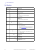
Pin Smart Card Contact Points DB-9 Smart Card Contact Points
1 C1 (VCC) 6 C6 (Vpp)
2 C2 (Reset) 7 C7 (I/O)
3 C3 (Clock) 8 C8 (RFU)
4C4 (RFU)
9
(GND when chip
is at station)
5 C5 (GND)
DB-9 Connector location for
Smart Card Contact Station