Zebra® R110PAX3™ Print Engine User Guide
© 2004 ZIH Corp. The copyrights in this manual and the label print engine described therein are owned by Zebra Technologies. Unauthorized reproduction of this manual or the software in the label print engine may result in imprisonment of up to one year and fines of up to $10,000 (17 U.S.C.506). Copyright violators may be subject to civil liability. All product names and numbers are Zebra trademarks, and Zebra, the Zebra logo, ZPL, ZPL II, ZebraNet, ZebraLink, are registered trademarks of ZIH Corp.
Contents About This Document . . . . . . . . . . . . . . . . . . . . . . . . . . . . . . . . . . . . . . . . . . . . . . . 1 Who Should Use This Document . . . . . . . . . . . . . . . . . . . . . . . . . . . . . . . . . . . . . . . . . . . . How This Document Is Organized . . . . . . . . . . . . . . . . . . . . . . . . . . . . . . . . . . . . . . . . . . . Contacts . . . . . . . . . . . . . . . . . . . . . . . . . . . . . . . . . . . . . . . . . . . . . . . . . . . . . . . . . . . . . . . Support . . . . .
Contents Select a Communication Interface . . . . . . . . . . . . . . . . . . . . . . . . . . . . . . . . . . . . . . . . . . Standard Connections . . . . . . . . . . . . . . . . . . . . . . . . . . . . . . . . . . . . . . . . . . . . . . . . Optional Print Servers. . . . . . . . . . . . . . . . . . . . . . . . . . . . . . . . . . . . . . . . . . . . . . . . . DB-15 Applicator Interface Connector . . . . . . . . . . . . . . . . . . . . . . . . . . . . . . . . . . . . System Considerations. . . . . . . . .
Contents 6 • Routine Maintenance . . . . . . . . . . . . . . . . . . . . . . . . . . . . . . . . . . . . . . . . . . . 89 Cleaning Schedule . . . . . . . . . . . . . . . . . . . . . . . . . . . . . . . . . . . . . . . . . . . . . . . . . . . . . . Clean Exterior . . . . . . . . . . . . . . . . . . . . . . . . . . . . . . . . . . . . . . . . . . . . . . . . . . . . . . . . . . Clean Interior . . . . . . . . . . . . . . . . . . . . . . . . . . . . . . . . . . . . . . . . . . . . . . . . . . . . . . . . . .
Contents B • Data Ports . . . . . . . . . . . . . . . . . . . . . . . . . . . . . . . . . . . . . . . . . . . . . . . . . . . 125 Parallel Port . . . . . . . . . . . . . . . . . . . . . . . . . . . . . . . . . . . . . . . . . . . . . . . . . . . . . . . . . . Serial Port . . . . . . . . . . . . . . . . . . . . . . . . . . . . . . . . . . . . . . . . . . . . . . . . . . . . . . . . . . . . Serial Pin Configuration . . . . . . . . . . . . . . . . . . . . . . . . . . . . . . . . . . . . . . . . . . . . . .
About This Document This section provides you with contact information, document structure and organization, and additional reference documents. Contents Who Should Use This Document . . . . . . . . . . . . . . . . . . . . . . . . . . . . . . . . . . . . . . . . . . . . How This Document Is Organized . . . . . . . . . . . . . . . . . . . . . . . . . . . . . . . . . . . . . . . . . . . Contacts . . . . . . . . . . . . . . . . . . . . . . . . . . . . . . . . . . . . . . . . . . . . . . . . . . . . . . . . .
About This Document Who Should Use This Document Who Should Use This Document This User Guide is intended for use by any person who needs to operate or troubleshoot problems with the print engine. How This Document Is Organized The User Guide is set up as follows: Section Description Print Engine Basics on page 7 This chapter provides a high-level overview of the print engine and its components.
About This Document Contacts Contacts You can contact Zebra Technologies at any of the following: Visit us at: http://www.zebra.com Our Mailing Addresses: Zebra Technologies Corporation 333 Corporate Woods Parkway Vernon Hills, Illinois 60061.3109 U.S.A Telephone: +1 847.634.6700 Fax: +1 847.913.
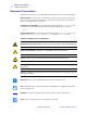
About This Document Document Conventions Document Conventions The following conventions are used throughout this document to convey certain information: Alternate Color (online only) Cross-references contain hot links to other sections in this guide. If you are viewing this guide online in .pdf format, you can click the cross-reference (blue text) to jump directly to its location. Command Line Examples All command line examples appear in Courier New font.
About This Document Related Documents Illustration Callouts Callouts are used when an illustration contains information that needs to be labeled and described. A table that contains the labels and descriptions follows the graphic. Figure 1 provides an example. Figure 1 • Sample Figure with Callouts 1 1 2 2 SETUP/EXIT button CALIBRATE button Related Documents The following documents might be helpful references: • ZPL II® Programming Guide Volume I (part number 45541L) and Volume II (part number 45542L).
About This Document Related Documents Notes • ___________________________________________________________________ __________________________________________________________________________ __________________________________________________________________________ __________________________________________________________________________ __________________________________________________________________________ __________________________________________________________________________ _____________________
1 Print Engine Basics This chapter provides a high-level overview of the print engine and its components. Contents Print Engine Exterior View . . . . . . . . . . . . . . . . . . . . . . . . . . . . . . . . . . . . . . . . . . . . . . . . . 8 Front Panel. . . . . . . . . . . . . . . . . . . . . . . . . . . . . . . . . . . . . . . . . . . . . . . . . . . . . . . . . . . . . 9 Front Panel Buttons . . . . . . . . . . . . . . . . . . . . . . . . . . . . . . . . . . . . . . . . . . . . . . . . . . . .
Print Engine Basics Print Engine Exterior View Print Engine Exterior View The print engine is available in a right-hand configuration (media moves from left to right, Figure 2). Figure 2 • Right-Hand (RH) Print Engine 3 2 1 1 2 3 8 Media Door Front Panel Power Switch R110PAX3 User Guide 9/7/2004 58981L-001 Rev.
Print Engine Basics Front Panel Front Panel All controls and indicators for the print engine are located on the front of the print engine on the front panel (Figure 3). The Liquid Crystal Display (LCD) shows operating status and feature parameters. The front panel buttons are used to control the print engine operations and to set parameters. The front panel lights (LEDs) indicate the print engine’s status.
Print Engine Basics Front Panel Table 1 • Front Panel Buttons (Continued) Button Description/Function FEED Feeds a blank label. • If the print engine is idle or paused, the label is fed immediately. • If the print engine is printing, the label is fed after the current batch finishes printing. CALIBRATE CALIBRATE functions only in PAUSE mode. Press CALIBRATE to recalibrate for proper media length, to set media type (continuous/non-continuous), and to set print method (direct thermal/thermal transfer).
Print Engine Basics Power On/Off Switch Power On/Off Switch The power on/off switch is located on the top of the print engine housing, as shown in Figure 4. When this switch is placed in the ON (I) position, the POWER light turns on, and the print engine automatically performs a Power-On Self Test (POST). For more information, see Power-On Self Test on page 110. Figure 4 • Print Engine Power Switch 58981L-001 Rev.
Print Engine Basics Power On/Off Switch Notes • ___________________________________________________________________ __________________________________________________________________________ __________________________________________________________________________ __________________________________________________________________________ __________________________________________________________________________ __________________________________________________________________________ ___________________
2 Getting Started This chapter provides the tasks that you must complete and the issues that you must consider before you load and configure your print engine. Contents Before You Begin . . . . . . . . . . . . . . . . . . . . . . . . . . . . . . . . . . . . . . . . . . . . . . . . . . . . . . . Unpack and Inspect the Print Engine. . . . . . . . . . . . . . . . . . . . . . . . . . . . . . . . . . . . . . . . Report Shipping Damage. . . . . . . . . . . . . . . . . . . . . . . . . . . . . . . . . . . . . . .
Getting Started Before You Begin Before You Begin Review this checklist, and resolve any issues before you begin setting up your print engine. When you are ready, continue with Print Engine Operation on page 31. Unpack and Inspect the Print Engine Have you unpacked the print engine and inspected it for damage? If you have not, see Unpack and Inspect the Print Engine on page 15.
Getting Started Unpack and Inspect the Print Engine Unpack and Inspect the Print Engine When you unpack the print engine, save all packing materials. Inspect the print engine for possible damage incurred during shipment. Check all exterior surfaces for damage. Raise the media door, and inspect the media compartment for damage to components. Report Shipping Damage If you discover shipping damage upon inspection: • Immediately notify the shipping company of the damage, and file a damage report with them.
Getting Started Print Engine Installation Print Engine Installation This section provides basic information for mounting the print engine into an applicator. The illustrations in this section show the print engine from different angles and include measurements and clearance needs. Requirements Stability When the print engine is mounted, the complete assembly must be physically stable. When the print engine is loaded with ribbon and media, the equipment must not become physically unstable.
Getting Started Print Engine Installation Figure 5 • Front View 58981L-001 Rev.
Getting Started Print Engine Installation Figure 6 • Right Side View 18 R110PAX3 User Guide 9/7/2004 58981L-001 Rev.
Getting Started Print Engine Installation Figure 7 • Rear View 58981L-001 Rev.
Getting Started Print Engine Installation Figure 8 • Top View 20 R110PAX3 User Guide 9/7/2004 58981L-001 Rev.
Getting Started Print Engine Installation Install the Print Engine in an Applicator This section provides the basic instructions for installing the print engine into an applicator. Caution • If the print engine is installed improperly, it could fall out of the applicator and cause injury. The center mounting bolt and four mounting screws must be installed and secured. See Figure 9 for the location of the bolt and screws. To install the print engine into an applicator, complete these steps: 1.
Getting Started Connect the Print Engine to a Power Source Connect the Print Engine to a Power Source The power supply in the print engine automatically detects the applied line voltage and works in the 90 to 264 VAC, 48 to 62 Hz range. Refer to Figure 10. The AC power cord must have a three-prong female connector on one end that plugs into the mating AC power connector at the rear of the print engine. If a power cable was not included with your print engine, refer to Power Cord Specifications on page 23.
Getting Started Connect the Print Engine to a Power Source Power Cord Specifications Depending on how your print engine was ordered, a power cord may or may not be included. If one is not included or if the one included is not suitable for your requirements, refer to the following guidelines: • The overall cord length must be less than 9.8 ft (3.0 m). • The cord must be rated for at least 5 A, 250 V. • The chassis ground (earth) must be connected to ensure safety and reduce electromagnetic interference.
Getting Started Select a Communication Interface Select a Communication Interface The way that you connect your print engine to a data source depends on the communication options installed in the print engine. See Data Ports on page 125 for control signal descriptions and other additional information. Caution • Connecting a data communications cable while the power is ON may damage the print engine. Note • You must supply all interface cables for your application.
Getting Started Select a Communication Interface Optional Print Servers • External ZebraNet PrintServer II (PSII). For more information on PSII, see the PrintServer II User and Reference Guide (Zebra part number 45537L). DB-15 Applicator Interface Connector A DB-15 Applicator Interface Connector provides communication between the print engine and the associated applicator hardware. In some applications, control signal timing may be a critical element in the performance of the print engine.
Getting Started Select a Communication Interface Data Cable Requirements Data cables must be fully shielded and fitted with metal or metallized connector shells. Shielded cables and connectors are required to prevent radiation and reception of electrical noise. To minimize electrical noise pickup in the cable: • Keep data cables as short as possible. • Do not bundle the data cables tightly with the power cords. • Do not tie the data cables to power wire conduits.
Getting Started Types of Media Types of Media The print engine can use various types of media (Table 3). We strongly recommend the use of Zebra-brand supplies for continuous high-quality printing. A wide range of paper, polypropylene, polyester, and vinyl stock has been specifically engineered to enhance the printing capabilities of the printer and to ensure against premature printhead wear.
Getting Started Types of Media Table 3 • Types of Media (Continued) Media Type How It Looks Description Fanfold Media The media is folded in a zigzag pattern. RFID “Smart” Media (for use with RFID-capable print engines only) Each label has a radio frequency identification (RFID) chip and antenna inlay embedded between the label and the liner. The media is made from the same materials and adhesives as non-RFID labels.
Getting Started Ribbon Ribbon Ribbon is a thin film that is coated on one side with wax or wax resin, which is transferred to the media during the thermal transfer process. The media determines whether you need to use ribbon and how wide the ribbon must be. When ribbon is used, it must be as wide as or wider than the media being used. If the ribbon is narrower than the media, areas of the printhead are unprotected and subject to premature wear.
Getting Started Ribbon Adhesive Test If you have labels or sticky tape available, perform the adhesive test to determine which side of a ribbon is coated. This method works well for ribbon that is already installed. To perform an adhesive test, complete these steps: 1. Peel a label from its liner. 2. Press a corner of the sticky side of the label to the outer surface of the roll of ribbon. 3. Peel the label off of the ribbon. 4. Observe the results.
3 Print Engine Operation If you have completed the tasks and resolved issues in the checklist in Before You Begin on page 14, use this chapter to load the print engine, to calibrate the print engine, and to print configuration labels. Contents Load Media . . . . . . . . . . . . . . . . . . . . . . . . . . . . . . . . . . . . . . . . . . . . . . . . . . . . . . . . . . . Load Ribbon. . . . . . . . . . . . . . . . . . . . . . . . . . . . . . . . . . . . . . . . . . . . . . . . . . . . . . . . . . .
Print Engine Operation Load Media Load Media Figure 17 identifies the media-handling components. Figure 18 on page 33 shows the print engine with media loaded.
Print Engine Operation Load Media Figure 18 • Loaded Media To load media, complete these steps: 1. Load media on the media supply reel of the applicator (refer to the applicator’s user guide). 2. Open the media door. 3. See Figure 19. Press the release button on the pinch roller assembly, and allow the assembly to pivot up. Figure 19 • Opening the Pinch Roller 1 2 1 2 58981L-001 Rev.
Print Engine Operation Load Media 4. See Figure 20. Slide the outer media guide all the way out. Figure 20 • Sliding the Outer Media Guide 1 1 Outer media guide 5. See Figure 21. Open the printhead assembly by unlatching the printhead latch from the locking pin. Caution • The printhead may be hot and could cause severe burns. Allow the printhead to cool. Figure 21 • Opening the Printhead Assembly 1 2 1 2 34 Printhead latch Locking pin R110PAX3 User Guide 9/7/2004 58981L-001 Rev.
Print Engine Operation Load Media 6. See Figure 22. Thread the media under the upper guide post, below the pinch roller assembly, and under the printhead assembly. 7. See Figure 22. Extend approximately 30 in. (75 cm) of media past the peel bar. Remove and discard the labels from this exposed media. Figure 22 • Threading the Media 1 2 3 4 5 1 2 3 4 5 58981L-001 Rev.
Print Engine Operation Load Media 8. See Figure 23. Position the media so that it is aligned with and just touching the inner media guide. 9. See Figure 23. Position the outer media guide so that it just touches the outer edge of the media. Figure 23 • Adjusting the Outer Media Guide 1 2 3 1 2 3 Inner media guide Outer media guide Media 10. See Figure 19 on page 33. Press down on the pinch roller assembly until it locks closed. 11. See Figure 21 on page 34.
Print Engine Operation Load Media 13. See Figure 25. Thread the media liner around the peel bar, under the media liner roller, and through the peel roller assembly. Note • If the applicator has an air tube, route the media liner between the air tube and the peel bar. Do not thread the media liner over the air tube. Figure 25 • Threading the Liner 1 1 2 3 4 2 3 4 Lower guide post Peel bar Media liner roller Peel roller assembly 14. See Figure 26.
Print Engine Operation Load Ribbon Load Ribbon Use ribbon with thermal transfer media. The ribbon must be coated on the outside and wider than the media. If the ribbon is narrower than the media, areas of the printhead are unprotected and subject to premature wear. Figure 27 identifies the ribbon system components inside the media compartment of a right-hand print engine. Figure 28 on page 39 shows the print engine with ribbon loaded.
Print Engine Operation Load Ribbon Figure 28 • Loaded Ribbon To load ribbon, complete these steps: 1. See Figure 29. Place a full ribbon roll onto the ribbon supply spindle so the ribbon rotates as shown, and then push the roll toward the print engine frame until it is fully seated. Figure 29 • Placing Ribbon on the Ribbon Supply Spindle 1 1 58981L-001 Rev.
Print Engine Operation Load Ribbon 2. See Figure 30. On the lower dancer assembly, squeeze the opening tabs to pivot open the dancer arm. 3. See Figure 30. Carefully thread the ribbon through the lower dancer assembly, and then slowly release the dancer arm. Figure 30 • Opening a Dancer Assembly 1 1 2 2 Opening tabs Ribbon 4. See Figure 31. Thread the ribbon between the ribbon sensor and the ribbon sensor reflector.