Zebra® 105SL™ Industrial/Commercial Printer User Guide
© 2006 ZIH Corp. The copyrights in this manual and the software and/or firmware in the label printer described therein are owned by ZIH Corp. Unauthorized reproduction of this manual or the software and/or firmware in the label printer may result in imprisonment of up to one year and fines of up to $10,000 (17 U.S.C.506). Copyright violators may be subject to civil liability. This product may contain ZPL®, ZPL II®, and ZebraLink™ programs; Element Energy Equalizer® Circuit; E3®; and Monotype Imaging fonts.
Declaration of Conformity I have determined that the Zebra printers identified as the SL Series 105SL manufactured by: Zebra Technologies Corporation 333 Corporate Woods Parkway Vernon Hills, Illinois 60061-3109 U.S.A. Have been shown to comply with the applicable technical standards of the FCC For Home, Office, Commercial, and Industrial use If no unauthorized change is made in the equipment, and if the equipment is properly maintained and operated.
iv Compliance Information Compliance Information FCC Compliance Statement This device complies with Part 15 rules. Operation is subject to the following two conditions: 1. This device may not cause harmful interference, and 2. This device must accept any interference received, including interference that may cause undesired operation. The user is cautioned that any changes or modifications not expressly approved by Zebra Technologies Corporation could void the user’s authority to operate the equipment.
Contents About This Document . . . . . . . . . . . . . . . . . . . . . . . . . . . . . . . . . . . . . . . . . . . . . . . 1 Who Should Use This Document . . . . . . . . . . . . . . . . . . . . . . . . . . . . . . . . . . . . . . . . . . . . How This Document Is Organized . . . . . . . . . . . . . . . . . . . . . . . . . . . . . . . . . . . . . . . . . . . Contacts . . . . . . . . . . . . . . . . . . . . . . . . . . . . . . . . . . . . . . . . . . . . . . . . . . . . . . . . . . . . . . . Web Site . . . .
vi Contents Select a Site for the Printer . . . . . . . . . . . . . . . . . . . . . . . . . . . . . . . . . . . . . . . . . . . . . . . . Select a Surface . . . . . . . . . . . . . . . . . . . . . . . . . . . . . . . . . . . . . . . . . . . . . . . . . . . . . Provide Proper Operating Conditions . . . . . . . . . . . . . . . . . . . . . . . . . . . . . . . . . . . . . Allow Proper Space . . . . . . . . . . . . . . . . . . . . . . . . . . . . . . . . . . . . . . . . . . . . . . . . . .
Contents Print a Configuration Label . . . . . . . . . . . . . . . . . . . . . . . . . . . . . . . . . . . . . . . . . . . . . . . . Print a Network Configuration Label . . . . . . . . . . . . . . . . . . . . . . . . . . . . . . . . . . . . . . . . . Control Panel Parameters. . . . . . . . . . . . . . . . . . . . . . . . . . . . . . . . . . . . . . . . . . . . . . . . . Print Server LCD Displays . . . . . . . . . . . . . . . . . . . . . . . . . . . . . . . . . . . . . . . . . . . . .
viii Contents Printing Specifications. . . . . . . . . . . . . . . . . . . . . . . . . . . . . . . . . . . . . . . . . . . . . . . . . . . Ribbon Specifications . . . . . . . . . . . . . . . . . . . . . . . . . . . . . . . . . . . . . . . . . . . . . . . . . . . Media Specifications . . . . . . . . . . . . . . . . . . . . . . . . . . . . . . . . . . . . . . . . . . . . . . . . . . . . Zebra Programming Language (ZPL II) . . . . . . . . . . . . . . . . . . . . . . . . . . . . . . . . . . . . . Bar Codes .
About This Document This section provides you with contact information, document structure and organization, and additional reference documents. Contents Who Should Use This Document . . . . . . . . . . . . . . . . . . . . . . . . . . . . . . . . . . . . . . . . . . . . How This Document Is Organized . . . . . . . . . . . . . . . . . . . . . . . . . . . . . . . . . . . . . . . . . . . Contacts . . . . . . . . . . . . . . . . . . . . . . . . . . . . . . . . . . . . . . . . . . . . . . . . . . . . . . . . .
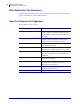
2 About This Document Who Should Use This Document Who Should Use This Document This User Guide is intended for use by any person who needs to perform routine maintenance, upgrade, or troubleshoot problems with the printer. How This Document Is Organized The User Guide is set up as follows: 11342L-001 Rev. A Section Description Introduction on page 7 This section shows the operational controls and location of major components used when loading media and ribbon.
About This Document Contacts Contacts You can contact Zebra Technologies Corporation at the following. Web Site http://www.zebra.com Technical Support via the Internet is available 24 hours per day, 365 days per year. Go to http://www.zebra.com/support. The Americas Regional Headquarters Technical Support Customer Service Dept. Zebra Technologies International, LLC 333 Corporate Woods Parkway Vernon Hills, Illinois 60061.3109 U.S.
4 About This Document Document Conventions Document Conventions The following conventions are used throughout this document to convey certain information. Alternate Color (online only) Cross-references contain hot links to other sections in this guide. If you are viewing this guide online in .pdf format, you can click the cross-reference (blue text) to jump directly to its location. LCD Display Examples Text from a printer’s Liquid Crystal Display (LCD) appears in Bubbledot ICG font.
About This Document Document Conventions Illustration Callouts Callouts are used when an illustration contains information that needs to be labeled and described. A table that contains the labels and descriptions follows the graphic. Figure 1 provides an example. Figure 1 • Sample Figure with Callouts PREVIOUS NEXT/SAVE SETUP/EXIT 1 POWER TAKE LABEL ERROR CHECK RIBBON PAPER OUT PAUSE FEED DATA CANCEL 1 6/30/06 SETUP/EXIT button 105SL User Guide 11342L-001 Rev.
6 About This Document Document Conventions Notes • ___________________________________________________________________ __________________________________________________________________________ __________________________________________________________________________ __________________________________________________________________________ __________________________________________________________________________ __________________________________________________________________________ _______________
1 Introduction This section shows the operational controls and location of major components used when loading media and ribbon. Other features of the printer are discussed. Contents External View . . . . . . . . . . . . . . . . . . . . . . . . . . . . . . . . . . . . . . . . . . . . . . . . . . . . . . . . . . . 8 Control Panel . . . . . . . . . . . . . . . . . . . . . . . . . . . . . . . . . . . . . . . . . . . . . . . . . . . . . . . . . . . 9 Control Panel LCD . . . . . . . . . . . . . . . . . . . . .
8 Introduction External View External View Figure 2 shows the outside of the printer. Figure 2 • Exterior of Printer Front 1 2 Rear 3 4 5 1 2 3 4 5 11342L-001 Rev.
Introduction Control Panel Control Panel All controls and indicators for the printer are located on the control panel (Figure 3). • The control panel Liquid Crystal Display (LCD) shows the operating status and printer parameters. • The control panel buttons are used to control the printer operations and to set parameters. • The control panel lights (LEDs) show the printer’s operating status or indicate which control panel buttons are active.
10 Introduction Control Panel Control Panel LCD The control panel LCD functions differently in different printer modes. • In Operating mode, the LCD displays the printer’s status, sometimes in conjunction with a control panel light (see Control Panel Lights on page 11). • In Pause mode, the printer stops printing temporarily. • In Setup mode, you can use the control panel LCD to view or modify printer parameters (see Control Panel Parameters on page 79).
Introduction Control Panel Table 1 • Control Panel Buttons (Continued) Button Appearance Function MINUS Changes the parameter values. Common uses are to decrease a value, to answer “no,” to scroll through choices, or to change the cursor position while entering the password. PLUS Changes the parameter values. Common uses are to increase a value, to answer “yes,” to scroll through choices, or to change values while entering the password.
12 Introduction Control Panel Table 2 • Control Panel Lights (Continued) Light DATA (located above the CANCEL button) 11342L-001 Rev. A Appearance Status Indication Off Normal operation. No data being received or processed. On The printer is processing data or is printing. No data is being received. Flashing The printer is receiving data from or sending status information to the host computer.
Introduction Printer Media Compartment Printer Media Compartment Figure 4 shows a simplified view of the media compartment of your printer. Depending on installed options, your printer may look slightly different. Figure 4 • Media Compartment 4 5 6 7 3 2 8 1 9 1 2 3 4 5 6 7 8 9 6/30/06 Printhead-open lever Platen roller Cutter (optional) Ribbon take-up spindle Ribbon supply spindle Media supply hanger Media supply guide Outer media guide Rewind spindle (optional) 105SL User Guide 11342L-001 Rev.
14 Introduction Printer Media Compartment Notes • ___________________________________________________________________ __________________________________________________________________________ __________________________________________________________________________ __________________________________________________________________________ __________________________________________________________________________ __________________________________________________________________________ ________________
2 Printer Setup This section provides the tasks that you must complete and the issues that you must consider before you load and configure your printer. Contents Before You Begin . . . . . . . . . . . . . . . . . . . . . . . . . . . . . . . . . . . . . . . . . . . . . . . . . . . . . . . Handling the Printer . . . . . . . . . . . . . . . . . . . . . . . . . . . . . . . . . . . . . . . . . . . . . . . . . . . . . Unpack and Inspect the Printer . . . . . . . . . . . . . . . . . . . . . . . . . . . . . . . .
16 Printer Setup Before You Begin Before You Begin Review this checklist, and resolve any issues before you set up or use your printer. Unpack and Inspect the Printer Have you unpacked the printer and inspected it for damage? If you have not, see Unpack and Inspect the Printer on page 17. Select a Site Have you selected an appropriate location for the printer? If you have not, see Select a Site for the Printer on page 18.
Printer Setup Handling the Printer Handling the Printer This section describes how to handle your printer. Unpack and Inspect the Printer When you receive the printer, immediately unpack it and inspect for shipping damage. • Save all packing materials. • Check all exterior surfaces for damage. • Raise the media door, and inspect the media compartment for damage to components. If you discover shipping damage upon inspection: • Immediately notify the shipping company and file a damage report.
18 Printer Setup Select a Site for the Printer Select a Site for the Printer Consider the following when selecting an appropriate location for your printer. Select a Surface Select a solid, level surface of sufficient size and strength to accommodate the printer and other equipment (such as a computer), if necessary. The choices include a table, countertop, desk, or cart. For the printer’s weight and dimensions, see General Specifications on page 142.
Printer Setup Select a Communication Interface Select a Communication Interface The way that you connect your printer to a data source depends on the communication options installed in the printer. You may use any available connection to send commands and label formats from a host computer to the printer. Caution • Ensure that the printer power is off (O) before connecting data communications cables. Connecting a data communications cable while the power is on (I) may damage the printer.
20 Printer Setup Select a Communication Interface Types of Connections The method of connecting the printer to a data source depends on the communication options installed in the printer and the host computer. This section provides basic information about common interfaces. When communicating via the serial data port (RS-232), the baud rate, number of data and stop bits, the parity, and the XON/XOFF or DTR control should be set to match those of the host computer.
Printer Setup Select a Communication Interface IEEE 1284 Bidirectional Parallel A common communication method available on most personal computers and other hosts. • Advantages: Faster than the serial connection; cables and connectors are readily available from computer equipment stores and suppliers; easy to connect; two-way communication between the computer and the printer; no printer parameter changes required to match the host computer. • Disadvantages: Recommended cable length of only 6 feet (1.
22 Printer Setup Select a Communication Interface Optional Ethernet Print Servers Ethernet-based print servers also are available to connect your printer to a data source. Both wired and wireless options are available. Manuals are available at http://www.zebra.com/manuals or on the user CD that came with your printer. Note • The parallel connection on your printer is not operational when one of these print servers is installed.
Printer Setup Connect the Printer to a Power Source Connect the Printer to a Power Source The AC power cord must have a three-prong female connector on one end that plugs into the mating AC power connector at the rear of the printer. If a power cable was not included with your printer, refer to Power Cord Specifications on page 24. Caution • For personnel and equipment safety, always use an approved three-conductor power cord specific to the region or country intended for installation.
24 Printer Setup Connect the Printer to a Power Source Power Cord Specifications Caution • For personnel and equipment safety, always use an approved three-conductor power cord specific to the region or country intended for installation. This cord must use an IEC 320 female connector and the appropriate region-specific, three-conductor grounded plug configuration. Depending on how your printer was ordered, a power cord may or may not be included.
Printer Setup Types of Media Types of Media The printer can use various types of media (Table 5). Zebra strongly recommends the use of Zebra-brand supplies for continuous high-quality printing. A wide range of paper, polypropylene, polyester, and vinyl stock has been specifically engineered to enhance the printing capabilities of the printer and to prevent premature printhead wear. To purchase supplies, go to http://www.zebra.com/howtobuy.
26 Printer Setup Types of Media Table 5 • Types of Media (Continued) Media Type How It Looks Description Non-Continuous Fanfold Media Fanfold media is folded in a zigzag pattern. Fanfold media can have the same label divisions as noncontinuous roll media. The divisions would fall on or near the folds. Continuous Roll Media Continuous media is wound on a core and is without gaps, holes, notches, or black marks. This allows the image to be printed anywhere on the label.
Printer Setup Ribbon Overview Ribbon Overview Ribbon is a thin film that is coated on one side with wax, resin, or wax resin, which is transferred to the media during the thermal transfer process. The media determines whether you need to use ribbon and how wide the ribbon must be. When ribbon is used, it must be as wide as or wider than the media being used. If the ribbon is narrower than the media, areas of the printhead are unprotected and subject to premature wear.
28 Printer Setup Ribbon Overview Adhesive Test If you have labels available, perform the adhesive test to determine which side of a ribbon is coated. This method works well for ribbon that is already installed. To perform an adhesive test, complete these steps: 1. Peel a label from its liner. 2. Press a corner of the sticky side of the label to the outer surface of the roll of ribbon. 3. Peel the label off of the ribbon. 4. Observe the results.
3 Operations This section provides the procedures for loading and calibrating the printer. Note • Complete the tasks and resolve the issues in Printer Setup on page 15 before operating the printer. Contents Media Loading Overview . . . . . . . . . . . . . . . . . . . . . . . . . . . . . . . . . . . . . . . . . . . . . . . . . Print Modes . . . . . . . . . . . . . . . . . . . . . . . . . . . . . . . . . . . . . . . . . . . . . . . . . . . . . . . . . Insert Media into the Printer. . . . . . . . . . . . .
30 Operations Media Loading Overview Media Loading Overview The printer can print on roll or fanfold media and use different print modes for label removal. Print Modes The methods for loading media for each print mode follow in this section. Use a print mode that matches the media being used and the printer options available (Table 6). For more information on the types of media, see Types of Media on page 25. Table 6 • Print Modes 11342L-001 Rev.
Operations Media Loading Overview Insert Media into the Printer This section shows how to insert roll or fanfold media into the printer. Fanfold media is loaded the same way as roll media. Roll Media To insert roll media, complete these steps: 1. Remove and discard any tags or labels that are dirty or that are held by adhesives or tape. Labels Tag Stock 2. Pull out the media supply guide as far as it goes. 3. Place the roll of media on the media supply hanger. Push the roll as far back as it will go.
32 Operations Media Loading Overview 4. Slide in the media supply guide until it touches the edge of the roll. Fanfold Media To load fanfold media, complete these steps: 1. Thread the fanfold media through the rear access slot (1) or the bottom access slot (2). Using the media supply hanger is optional. Figure 15 • Rear Feed Using Media Supply Hanger 1 Figure 16 • Bottom Feed Without Using Media Supply Hanger 2 11342L-001 Rev.
Operations Media Loading Overview 2. Do you wish to use the media supply guide? 6/30/06 If… Then… No Continue with the media loading procedure for the desired print mode. Yes a. Pull the media supply guide out as far as it goes. b. Drape the media over the media supply hanger. c. Slide in the media supply guide until it touches, but does not restrict, the edge of the media. 105SL User Guide 11342L-001 Rev.
34 Operations Load Media in Tear-Off Mode Load Media in Tear-Off Mode Tear-Off is the default mode. Figure 17 shows roll media loaded in Tear-Off mode. Figure 17 • Tear-Off Mode 1 2 1 2 3 4 5 3 4 5 Printed label Printhead-open lever Outer media guide Media supply hanger Media supply guide To load media in Tear-Off mode, complete these steps: 1. Set the printer to Tear-Off mode. See Select Print Mode on page 80 for instructions. 2. Insert media into the printer.
Operations Load Media in Tear-Off Mode 4. Loosen the thumb screw (not visible from this angle) that is located on the bottom of the outer media guide (1). 1 5. Slide the outer media guide all the way out. 6. Thread the media under the lower roller (1) and the upper media sensor assembly (2). 2 1 6/30/06 105SL User Guide 11342L-001 Rev.
36 Operations Load Media in Tear-Off Mode 7. Push the media forward until it passes under the printhead assembly (1), under the snap plate (2), and then over the platen roller (3). 1 2 3 8. Align the media with the inner media guide (1). Slide in the outer media guide (2) until it just touches the edge of the media. 1 2 11342L-001 Rev.
Operations Load Media in Tear-Off Mode 9. Tighten the thumb screw (not visible from this angle) that is located on the bottom of the outer media guide (1). 1 10. Push down the printhead assembly (1), and then rotate the printhead-open lever clockwise until it locks into place (2). 2 6/30/06 1 105SL User Guide 11342L-001 Rev.
38 Operations Load Media in Peel-Off Mode Load Media in Peel-Off Mode Refer to Figure 18. This section applies only if the Rewind option or the Peel option is installed. Figure 18 • Peel-Off Mode 1 2 3 4 5 4 5 Rewind option operating in Peel-Off mode 8 6 7 1 2 3 Peel option operating in Peel-Off mode 8 9 1 2 3 4 5 11342L-001 Rev.
Operations Load Media in Peel-Off Mode To load media in Peel-Off mode, complete these steps: 1. Prepare the printer for Peel-Off mode. 6/30/06 If the printer has the… Then… Rewind option a. If the rewind plate is installed, remove it from the print mechanism. b. Hang the rewind plate upside-down on the two mounting screws on the inside of the front panel. Secure the rewind plate to the front panel with two thumb nuts. 105SL User Guide 11342L-001 Rev.
40 Operations Load Media in Peel-Off Mode If the printer has the… Then… Peel option a. Remove the two thumb nuts that secure the front cover bracket to the mounting screws on the inside of the front panel. b. Remove the front cover bracket from the printer and store it. 2. Set the printer to Peel-Off mode. See Select Print Mode on page 80 for instructions. 3. Insert media into the printer. See Insert Media into the Printer on page 31 for instructions. 4.
Operations Load Media in Peel-Off Mode 5. Loosen the thumb screw on the bottom of the outer media guide (not visible from this angle). 6. Slide the outer media guide all the way out. 7. Thread the media past the inner media guide (1). Continue under the lower roller (2) and the upper media sensor (3). Ensure that the media touches the inner media guide. 3 2 1 6/30/06 105SL User Guide 11342L-001 Rev.
42 Operations Load Media in Peel-Off Mode 8. Thread the media forward until it passes under the printhead assembly (1), under the snap plate (2), over the platen roller (3), and out the front of the printer (4). 1 2 4 3 9. Extend approximately 36 in. (920 mm) of media out of the printer. Remove and discard the labels from this exposed media. 11342L-001 Rev.
Operations Load Media in Peel-Off Mode 10. Wind the media liner around the rewind or peel spindle as instructed. If the printer has the… Then… Rewind option Note • You may opt to install a core on the rewind spindle for the used media liner. However, a core is not required and typically is not used for peel-off mode. a. Remove the hook from the rewind spindle. b. Wind the media liner counterclockwise around the rewind spindle. c. Reinstall the hook.
44 Operations Load Media in Peel-Off Mode 11342L-001 Rev. A If the printer has the… Then… Peel option a. Remove the hook from the peel spindle. b. Wind the media liner counterclockwise around the peel spindle. c. Reinstall the hook. The short end of the hook fits into the notch on the peel spindle. The long end of the hook fits into the groove on the opposite side of the notch. d. Rotate the spindle counterclockwise several turns to wind the media liner over the hook and remove any slack.
Operations Load Media in Peel-Off Mode 11. Align the media with the inner media guide (1). Slide in the outer media guide (2) until it just touches the edge of the media. 1 2 12. Tighten the thumb screw on the bottom of the outer media guide (not visible from this angle). 6/30/06 105SL User Guide 11342L-001 Rev.
46 Operations Load Media in Peel-Off Mode 13. Push the printhead assembly down (1), and then rotate the printhead-open lever clockwise until it locks into place (2). 2 11342L-001 Rev.
Operations Load Media in Peel-Off Mode Remove Media Liner from the Rewind or Peel Spindle Rewind mode and Peel-Off mode each use spindles to wind used media liner. Remove the media liner from the spindle each time that you change labels. Important • It is not necessary to turn off the power to remove media liner from the spindles. If power is turned off, all label formats and images, as well as any temporarily saved parameter settings stored in the printer’s internal memory, are lost.
48 Operations Load Media in Peel-Off Mode 2. Pull out the spindle hook. Rewind Peel 3. Slide the media liner off of the spindle and discard. Rewind Peel 11342L-001 Rev.
Operations Load Media in Rewind Mode Load Media in Rewind Mode Refer to Figure 19. This section applies only if the Rewind option is installed. Use a 3-inch core on the rewind spindle to wind printed labels. Note • Before closing the printhead, make sure that: • The media is positioned against the inside guides. • The media is taut and parallel with itself and the pathway when wound onto the rewind spindle or core.
50 Operations Load Media in Rewind Mode To load media in Rewind mode, complete these steps: 1. Is the rewind plate installed as shown in Figure 19? If… Then… Yes Continue with the next step No a. Remove the rewind plate from its storage location in front of the print mechanism inside the media compartment. b. Invert the rewind plate so that the top lip (1) and the adjustable hook plate (2) point down. 1 2 c.
Operations Load Media in Rewind Mode 4. Open the printhead assembly by rotating the printhead-open lever counterclockwise. 5. Loosen the thumb screw on the bottom of the outer media guide (not visible from this angle). 6. Slide the outer media guide all the way out. 6/30/06 105SL User Guide 11342L-001 Rev.
52 Operations Load Media in Rewind Mode 7. Thread the media past the inner media guide (1). Continue under the lower roller (2) and the upper media sensor (3). Ensure that the media touches the inner media guide. 3 2 1 8. Thread the media forward until it passes under the printhead assembly (1), under the snap plate (2), over the platen roller (3), and out the front of the printer (4). 1 2 4 11342L-001 Rev.
Operations Load Media in Rewind Mode 9. Extend approximately 36 in. (920 mm) of media out of the printer. Remove and discard the labels from this exposed media. 10. Remove the hook from the rewind spindle. Store the hook in the bottom of the printer. 11. Slide an empty 3-in. (76.2-mm) core onto the rewind spindle until it is flush against the guide plate. 6/30/06 105SL User Guide 11342L-001 Rev.
54 Operations Load Media in Rewind Mode 12. Rotate the rewind spindle counterclockwise several turns to wind the media liner around the core and remove any slack. 13. Align the media with the inner media guide (1). Slide in the outer media guide (2) until it just touches the edge of the media. 1 2 14. Tighten the thumb screw on the bottom of the outer media guide (not visible from this angle). 11342L-001 Rev.
Operations Load Media in Rewind Mode 15. Push the printhead assembly down (1), and then rotate the printhead-open lever clockwise until it locks into place (2). 2 1 Remove Labels from the Rewind Spindle Rewind mode uses a core to wind printed labels. Remove the core with the printed labels every time you change labels for the Rewind option to work correctly. Important • It is not necessary to turn off the power to remove printed labels.
56 Operations Load Media in Rewind Mode If... Then... No a. Rotate the rewind spindle clockwise to create slack in the media. b. Cut or tear the media between labels. 2. Slide the core from the rewind spindle. 11342L-001 Rev.
Operations Load Media in Cutter Mode Load Media in Cutter Mode Refer to Figure 20. The following instructions pertain to printers with the cutter option only. Figure 20 • Cutter Mode 1 2 3 4 5 6 1 2 3 4 5 6 Printed label Printhead-open lever Outer media guide Media supply hanger Media supply guide Cutter To load media in Cutter mode, complete these steps: 1. Set the printer to Cutter mode. See Select Print Mode on page 80 for instructions. 2. Insert media into the printer.
58 Operations Load Media in Cutter Mode 4. Loosen the thumb screw on the bottom of the outer media guide (not visible from this angle). 5. Slide the outer media guide all the way out. 6. Thread the media past the inner media guide (1). Continue under the lower roller (2) and the upper media sensor (3). Ensure that the media touches the inner media guide. 3 2 1 11342L-001 Rev.
Operations Load Media in Cutter Mode 7. Caution • The cutter blade is sharp. Do not touch or rub the blade with your fingers. Thread the media forward until it passes under the printhead assembly (1), under the snap plate (2), and through the cutter assembly (3). (An optional cutter catch tray (4) is shown in this illustration.) 1 2 3 4 8. Align the media with the inner media guide (1). Slide in the outer media guide (2) until it just touches the edge of the media.
60 Operations Load Media in Cutter Mode 9. Tighten the thumb screw on the bottom of the outer media guide (not visible from this angle). 10. Push the printhead assembly down (1), and then rotate the printhead-open lever clockwise until it locks into place (2). The printer automatically feeds and cuts one label after the printhead is closed. 2 11342L-001 Rev.
Operations Load Ribbon Load Ribbon Always use ribbon that is wider than the media to protect the printhead from wear. Ribbon must be coated on the outside (see Coated Side of Ribbon on page 27 to determine which side of a ribbon is coated). For direct thermal printing, do not load ribbon in the printer. Figure 21 • Ribbon Path To load ribbon, complete these steps: 1. Align the segments of the ribbon supply spindle. 2. Orient the ribbon with the loose end unrolling clockwise. 3.
62 Operations Load Ribbon 4. A ribbon leader makes ribbon loading and unloading easier. Does your roll of ribbon have paper or something else attached to the end to serve as a ribbon leader? If… Then… Yes Continue with the next step. No a. Tear off a strip of media (labels and liner) about 6–12 in. (150–305 mm) long from the roll. b. Peel a label from the media strip. c. Use this label (1) to attach the end of the ribbon (2) to the media strip (3). The media strip acts as a leader. 3 1 2 5.
Operations Load Ribbon 7. Push the ribbon leader forward until it passes under the printhead assembly (1), over the snap plate (2), and then over the platen roller (3). 1 2 3 8. Bring the ribbon leader over the upper ribbon roller (1) and toward the ribbon take-up spindle (2). 1 2 9. Remove the hook from the ribbon take-up spindle. 6/30/06 105SL User Guide 11342L-001 Rev.
64 Operations Load Ribbon 10. Wind the ribbon leader and the attached ribbon counterclockwise around the ribbon take-up spindle. 11. Reinstall the hook. The short end of the hook fits into the notch on the ribbon take-up spindle. The long end of the hook fits into the groove on the opposite side of the notch. 12. Rotate the spindle counterclockwise several turns to wind the ribbon over the hook and remove any slack. 13.
Operations Load Ribbon Remove Used Ribbon Remove used ribbon from the ribbon take-up spindle each time you change the roll of ribbon. To remove used ribbon, complete these steps: 1. If the ribbon has not run out, cut or break it before the ribbon take-up spindle. 2. Push the hook until it slips out of the groove in the ribbon take-up spindle. Move the hook back and forth to loosen the ribbon. 3. Remove the loosened hook from the ribbon take-up spindle. 4.
66 Operations Adjust Media Sensors Adjust Media Sensors This section describes how to adjust the media sensors. Black Mark Sensor The optional black mark sensor is in a fixed position and is enabled via the control panel (see Set the Sensor Type on page 81 for details). Transmissive Sensor The transmissive sensor, which is used to detect web media, consists of two sections: a light source (the lower media sensor) and a light sensor (the upper media sensor). The media passes between the two.
Operations Adjust Media Sensors 3. Using a Phillips-head screwdriver, slightly loosen the upper media sensor adjustment screw (1). 1 4. Using the tip of the screwdriver, slide the upper sensor along the slot to the desired position (for non-continuous media with a notch or hole in the media, the sensor must be directly above the notch or hole). 5. Tighten the upper media sensor adjustment screw. Lower Media Sensor To adjust the lower media sensor, complete these steps: 1.
68 Operations Adjust Printhead Balance and Pressure Adjust Printhead Balance and Pressure Printhead toggle position (balance) and printhead pressure affect print quality. If the pressure is too light or uneven, the labels and ribbon may slip. Important • Print quality depends on the labels and ribbon used as well as the toggle position and pressure. Make sure that your labels and ribbon are right for your application.
Operations Adjust Printhead Balance and Pressure 5. Tighten the locking nut. 6. Print additional labels at 2.4 in. (61 mm) per second by again running the PAUSE Self Test on page 133. 7. Do both sides of the label print at the same level of gray? If… Then… Yes The toggle is positioned correctly. Increase the darkness setting to the optimum level for the media being used. No a. b. c. d. e. f. 6/30/06 Loosen the locking nut at the top of the toggle assembly.
70 Operations Adjust Printhead Balance and Pressure Printhead Pressure Adjustment You may need to increase the printhead pressure if you are using thick media or if the ribbon slips during printing. To maximize printhead life, use the lowest pressure that produces the desired print quality without allowing the ribbon or media to slip. To change printhead pressure, complete these steps: 1. Loosen the upper knurled nut on the toggle assembly. 2.
Operations Calibrate the Printer Calibrate the Printer Calibrate the printer when it is first put into service. Calibration allows the printer to establish the proper settings for the specific media and ribbon used in your application. You may calibrate the printer at other times as needed. Table 7 shows the different methods for calibration.
72 Operations Calibrate the Printer Table 7 • Types of Calibration (Continued) Type of Calibration Description When/How It Occurs Media and Ribbon Sensor Sensitivity Calibration This calibration is one of the most common adjustments made to printer settings. The printer resets the sensitivity of the sensors specifically for the media and ribbon that you are using. If you change the type of ribbon and/or media, you might need to reset the sensitivity of the media and ribbon sensors.
4 Configuration This section describes the control panel parameters that are used to configure the printer for operation. Contents Setup Mode . . . . . . . . . . . . . . . . . . . . . . . . . . . . . . . . . . . . . . . . . . . . . . . . . . . . . . . . . . . Enter Setup Mode . . . . . . . . . . . . . . . . . . . . . . . . . . . . . . . . . . . . . . . . . . . . . . . . . . . . Exit Setup Mode. . . . . . . . . . . . . . . . . . . . . . . . . . . . . . . . . . . . . . . . . . . . . . . . . . . . . .
74 Configuration Setup Mode Setup Mode After you have installed the media and ribbon and the Power-On Self Test (POST) is complete, the control panel displays PRINTER READY. You may now set printer parameters for your application using the control panel display and the buttons directly below it. If it becomes necessary to restore the initial printer defaults, see FEED and PAUSE Self Test on page 138.
Configuration Setup Mode Exit Setup Mode To leave Setup mode, complete these steps: 1. Press SETUP/EXIT. The LCD displays SAVE CHANGES. 2. Press PLUS (+) or MINUS (-) to display the save options (Table 8). Table 8 • Save Options When Leaving Setup Mode LCD Description PERMANENT Stores values in the printer even when power is turned off. TEMPORARY Saves the changes until power is turned off.
76 Configuration Change Password-Protected Parameters Change Password-Protected Parameters Certain parameters, including the communication parameters, are password-protected by factory default. Caution • Do not change password-protected parameters unless you have a complete understanding of the parameters’ functions. If the parameters are set incorrectly, the printer may function unpredictably. The first time that you attempt to change a password-protected parameter, the printer displays ENTER PASSWORD.
Configuration Print a Configuration Label Print a Configuration Label A configuration label lists the printer settings that are stored in configuration memory. After you load the media and ribbon (if necessary), print a configuration label as a record of your printer’s current settings. Keep the label to use when troubleshooting printing problems. To print a configuration label, complete these steps: 1. On the control panel, press SETUP/EXIT. 2.
78 Configuration Print a Network Configuration Label Print a Network Configuration Label If you are using a print server, you can print a network configuration label after the printer is connected to the network. To print a network configuration label, complete these steps: 1. On the control panel, press SETUP/EXIT. 2. Press NEXT or PREVIOUS to scroll through the parameters until you reach LIST NETWORK. 3. Press the PLUS (+) to confirm printing. A network configuration label prints (Figure 23).
Configuration Control Panel Parameters Control Panel Parameters Use the LCD on the control panel to adjust printer settings. Table 9 shows parameters in the order in which they are displayed when you press NEXT/SAVE after entering Setup mode. Table 10 on page 98 shows the additional parameters that appear when a wired or wireless print server is installed in the printer. Note • Your label preparation software or the printer driver may override adjustments made through the control panel.
80 Configuration Control Panel Parameters Table 9 • Printer Parameters (Page 2 of 19) Parameter TEAR OFF - Action/Explanation +000 + Adjust the Tear-Off Position This parameter establishes the position of the media over the tear-off/peel-off bar after printing. See Figure 24. Higher numbers move the media out (the tear line moves closer to the leading edge of the next label), and lower numbers move the media in (the tear line moves closer to the edge of the label just printed).
Configuration Control Panel Parameters Table 9 • Printer Parameters (Page 3 of 19) Parameter Action/Explanation Set Media Type This parameter tells the printer the type of media that you are using (see Types of Media on page 25 for more information). Selecting continuous media requires that you include a label length instruction in your label format (^LLxxxx if you are using ZPL or ZPL II).
82 Configuration Control Panel Parameters Table 9 • Printer Parameters (Page 4 of 19) Parameter PRINT WIDTH - MM + Action/Explanation Set Print Width Determines the printable area across the width of the label given the resolution of the printer. Note • Setting the width too narrow can result in portions of the label not being printed on the media. Setting the width too wide wastes formatting memory and can cause printing off the label and on the platen roller.
Configuration Control Panel Parameters Table 9 • Printer Parameters (Page 5 of 19) Parameter MAXIMUM LENGTH -39.0 IN 988 MM Action/Explanation Set Maximum Label Length This parameter is used during the media portion of the calibration process. Always set maximum label length to a value that is at least 1.0 in. (25.4 mm) greater than the actual label length (Figure 25).
84 Configuration Control Panel Parameters Table 9 • Printer Parameters (Page 6 of 19) Parameter LIST FONTS PRINT Action/Explanation List Fonts This option prints a label that lists the available fonts in the printer, including standard printer fonts plus any optional fonts. Fonts may be stored in RAM, Flash memory, optional PCMCIA font cards, or CompactFlash® cards. To print a list of the available fonts: 1. Press PLUS (+) to select PRINT.
Configuration Control Panel Parameters Table 9 • Printer Parameters (Page 7 of 19) Parameter LIST ALL Action/Explanation PRINT List All This option prints labels that list the available fonts, bar codes, images, formats, and the current printer and network configurations. To print labels for all settings: 1. Press PLUS (+) to select PRINT. FORMAT CARD: A: B: Format Memory Card This option erases all previously stored information from the optional PCMCIA card or Compact Flash card.
86 Configuration Control Panel Parameters Table 9 • Printer Parameters (Page 8 of 19) Parameter INIT FLASH MEM. YES Action/Explanation Initialize Flash Memory This option erases all previously stored information from Flash memory. Caution • This option completely erases the Flash memory. To initialize Flash memory: 1. Press PLUS (+) to select YES. If your printer is set to require a password, you are prompted to enter the password. 2. Enter the password.
Configuration Control Panel Parameters Table 9 • Printer Parameters (Page 9 of 19) Parameter SENSOR PROFILE PRINT Action/Explanation Print Sensor Profile A sensor profile shows sensor settings compared to actual sensor readings. This label (which will extend across several actual labels or tags) can be used to troubleshoot printing problems. To interpret the results of the sensor profile, see Sensor Profile on page 140. Figure 26 • Sensor Profile To print a sensor profile: 1.
88 Configuration Control Panel Parameters Table 9 • Printer Parameters (Page 10 of 19) Parameter MEDIA AND RIBBON CALIBRATE Action/Explanation Calibrate Media and Ribbon Sensor Sensitivity Use this procedure to adjust sensitivity of media and ribbon sensors. Important • Follow this procedure exactly as presented. All of the steps must be performed even if only one of the sensors requires adjustment. You may press MINUS (-) at any step in this procedure to cancel the process.
Configuration Control Panel Parameters Table 9 • Printer Parameters (Page 11 of 19) Parameter PARALLEL COMM. -BIDIRECTIONAL Action/Explanation + Set Parallel Communications Select the communications port that matches the one being used by the host computer. Default: BIDIRECTIONAL Selections: BIDIRECTIONAL, TWINAX/COAX, UNIDIRECTIONAL To change the value shown: 1. Press PLUS (+) or MINUS (-) to scroll through the options.
90 Configuration Control Panel Parameters Table 9 • Printer Parameters (Page 12 of 19) Parameter PARITY NONE Action/Explanation + Set Parity This setting applies only when the serial port is used. The parity of the printer must match the parity of the host computer for accurate communications to take place. Select the parity that matches the one being used by the host computer. Default: NONE Selections: EVEN, ODD, NONE To change the value shown: 1.
Configuration Control Panel Parameters Table 9 • Printer Parameters (Page 13 of 19) Parameter COMMUNICATIONS - NORMAL MODE Action/Explanation + Set Communications Mode The communication diagnostics mode is a troubleshooting tool for checking the interconnection between the printer and the host computer. For more information, see Communications Diagnostics Test on page 139. Default: NORMAL MODE Selections: NORMAL MODE, DIAGNOSTICS To select communication diagnostics mode: 1.
92 Configuration Control Panel Parameters Table 9 • Printer Parameters (Page 14 of 19) Parameter DELIMITER CHAR <,>2CH Action/Explanation + Set Delimiter Character The delimiter character is a two-digit hex value used as a parameter place marker in ZPL/ZPL II format instructions. See the ZPL II Programming Guide Volume I for more information. Note • Do not use the same hex value for the control, format, and delimiter character. The printer must see different characters to work properly.
Configuration Control Panel Parameters Table 9 • Printer Parameters (Page 15 of 19) Parameter HEAD CLOSE - CALIBRATION Action/Explanation + Select Head Close Option This parameter sets the action of the media when you close the printhead. Default: CALIBRATION Selections: FEED, CALIBRATION, LENGTH, SHORT CAL, and NO MOTION • Feed—feeds the labels to the first registration point. • Calibration—determines the length of the label and adjusts the sensor settings.
94 Configuration Control Panel Parameters Table 9 • Printer Parameters (Page 16 of 19) Parameter LEFT POSITION ±0000 Action/Explanation + Adjust Left Position This parameter establishes how far from the left edge of a label the format begins to print by adjusting horizontal positioning on the label. Positive numbers adjust the printing away from the main frame by the number of dots selected; negative numbers shift printing toward the main frame. The displayed value represents dots.
Configuration Control Panel Parameters Table 9 • Printer Parameters (Page 17 of 19) Parameter HEAD RESISTOR 0500 OHMS Action/Explanation Set the Printhead Resistor Value + Caution • This parameter should be changed only by qualified service personnel. Do not set the value higher than that shown on the printhead. Setting a higher value may damage the printhead. Note • Depending on the printer model that you have, this parameter may not be available.
96 Configuration Control Panel Parameters Table 9 • Printer Parameters (Page 18 of 19) Parameter Action/Explanation WEB S. - 073 MEDIA S. - 075 RIBBON S. - 071 To skip these parameters: + MARK S. - + 1. Press PLUS (+) repeatedly. + + 000 + MARK MED S. 000 - + MEDIA LED - 082 + RIBBON LED - 008 MARK LED - 005 LCD ADJUST - These parameters are automatically set during the calibration procedure and should be changed only by a qualified service technician.
Configuration Control Panel Parameters Table 9 • Printer Parameters (Page 19 of 19) Parameter RTC DATE - 01/31/01 Action/Explanation + Set Real-Time Clock (RTC) Date This parameter allows you to set the date following the convention selected in IDLE DISPLAY. To change the value shown: 1. Press MINUS (-) to move to the next digit position. 2. Press PLUS (+) to change the value of the digit.
98 Configuration Control Panel Parameters Print Server LCD Displays The menu options shown in Table 10 display only if you have a print server installed. Table 10 • Print Server Parameters (Page 1 of 4) Parameter LOAD LAN FROM? PRINTER Action/Explanation Load LAN Source1 This parameter, which serves the same function as the ^NP ZPL command, specifies whether to use the printer’s or the print server’s IP settings at bootup. Default: PRINTER Selections: PRINTER, PRINTSERVER To change the value shown: 1.
Configuration Control Panel Parameters Table 10 • Print Server Parameters (Page 2 of 4) Parameter IP ADDRESS 000.000.000.000 Action/Explanation Specify IP Address2 This parameter allows you to select the IP address if PERMANENT was chosen in IP PROTOCOL. (If a dynamic option was chosen, the user cannot select the address.) To change the value shown: 1. Press MINUS (–) to move the cursor. 2. Press PLUS () to increase the value of the digit. SUBNET MASK 000.000.000.
100 Configuration Control Panel Parameters Table 10 • Print Server Parameters (Page 3 of 4) Parameter LEAP MODE OFF Action/Explanation Enable LEAP Mode3,4 LEAP is an encryption method that is available with some wireless cards. Set the LEAP user name and password through the printer web pages. This parameter appears 1) when no wireless card is inserted or 2) when the wireless card is associated to the WLAN and the card supports LEAP. Default: OFF Selections: ON, OFF To change the value shown: 1.
Configuration Control Panel Parameters Table 10 • Print Server Parameters (Page 4 of 4) Parameter RESET NETWORK YES Action/Explanation Reset Network2,3 This option resets the wireless card and the print server when the wireless option is running. Selecting this option has no effect when the wireless option is not running, when there is no card inserted, or when the wireless password is anything other than the default (zero). 1. Press PLUS (+) to select YES. The LCD prompts ARE YOU SURE?. 2.
102 Configuration Control Panel Parameters Notes • ___________________________________________________________________ __________________________________________________________________________ __________________________________________________________________________ __________________________________________________________________________ __________________________________________________________________________ __________________________________________________________________________ _______________
5 PC and Memory Cards This section describes the optional cards that can be used with the printer and gives instructions for installation. Contents PCMCIA PC Cards. . . . . . . . . . . . . . . . . . . . . . . . . . . . . . . . . . . . . . . . . . . . . . . . . . . . . 104 6/30/06 105SL User Guide 11342L-001 Rev.
104 PC and Memory Cards PCMCIA PC Cards PCMCIA PC Cards The printer can use Type I- or Type II-compliant PCMCIA PC cards. These cards may hold extra memory or font options for the printer, or they may be wireless radio frequency (RF) cards that allow the printer to communicate over a network (ZebraNet Wireless Print Server option required). Caution • Observe proper electrostatic safety precautions when handling any static-sensitive components such as circuit boards and printheads.
PC and Memory Cards PCMCIA PC Cards 2. Insert the PCMCIA card into the card slot with the notch up. Insert it far enough to make the card-eject button pop out. 3. Reinstall the card shield over the PCMCIA card and card slot. Note • The PCMCIA card may take a few minutes to initialize. The PAUSE light flashes while the card initializes. If the card is already initialized, the PAUSE light flashes only once or twice after the card is installed.
106 PC and Memory Cards PCMCIA PC Cards Notes • ___________________________________________________________________ __________________________________________________________________________ __________________________________________________________________________ __________________________________________________________________________ __________________________________________________________________________ __________________________________________________________________________ __________________
6 Routine Maintenance This section provides routine cleaning and maintenance procedures. Contents Lubrication . . . . . . . . . . . . . . . . . . . . . . . . . . . . . . . . . . . . . . . . . . . . . . . . . . . . . . . . . . . Cleaning Schedule . . . . . . . . . . . . . . . . . . . . . . . . . . . . . . . . . . . . . . . . . . . . . . . . . . . . . Clean the Exterior . . . . . . . . . . . . . . . . . . . . . . . . . . . . . . . . . . . . . . . . . . . . . . . . . . . . .
108 Routine Maintenance Lubrication Lubrication Caution • No lubricating agents other than Zebra-supplied, silicon-only lubricants should be used on the spindle felt clutches of this printer. Other commercially available lubricants damage the finish and mechanical parts. Cleaning Schedule Cleaning your printer regularly maintains print quality and may extend the life of the printer. The recommended cleaning schedule is shown in Table 11. See the following pages for specific procedures.
Routine Maintenance Clean the Exterior Clean the Exterior Clean the outside surfaces of the printer with a lint-free cloth. Use a mild detergent solution or desktop cleaner sparingly, as needed. Caution • Do not use harsh or abrasive cleaning agents or solvents. Clean the Printhead and Platen Roller After every roll of ribbon, clean the printhead. Clean the printhead more often if you see inconsistent print quality, such as voids in the bar code or graphics.
110 Routine Maintenance Clean the Printhead and Platen Roller 3. See Figure 29. Using the swab from the Preventive Maintenance Kit (part number 47362), wipe along the brown strip on the printhead assembly from end to end. In place of the Preventive Maintenance Kit, you may use a clean swab dipped in a solution of isopropyl alcohol (minimum 90%) and deionized water (maximum 10%). Allow the solvent to evaporate.
Routine Maintenance Clean the Printhead and Platen Roller 6. Push the printhead assembly down (1), and then rotate the printhead-open lever clockwise until it locks into place (2). 2 6/30/06 1 105SL User Guide 11342L-001 Rev.
112 Routine Maintenance Clean the Media Compartment and Sensors Clean the Media Compartment and Sensors After every four rolls of media, inspect the media compartment. Use a soft bristle brush or a vacuum cleaner to remove any dirt and lint from the interior of the printer. The sensors should be cleaned on a regular basis to ensure proper operation of the printer. Brush or vacuum any accumulated paper lint and dust off of these sensors. To clean the media compartment and sensors, complete these steps: 1.
Routine Maintenance Clean the Media Compartment and Sensors Figure 32 • Take-Label Sensors, Black Mark Sensor, and Ribbon Sensor 1 2 1 2 3 6/30/06 3 Take-label sensors Black mark sensor Ribbon sensor 105SL User Guide 11342L-001 Rev.
114 Routine Maintenance Clean the Snap Plate Clean the Snap Plate Clean the snap plate to remove label adhesive or a label that has adhered to the underside of the snap plate. To clean the snap plate, complete these steps: 1. Caution • Do not bend, twist, or deform the loops in the snap plate. If the snap plate is damaged in any way, a new one may be required for proper ribbon sensing. Insert a small-blade screwdriver or similar tool into the loop on the left side of the snap plate.
Routine Maintenance Clean the Cutter Clean the Cutter If the cutter is not cutting the labels cleanly or if it jams with labels, clean the cutter. Caution • For personnel safety, always power off and unplug the printer before performing this procedure. To clean the cutter, complete these steps: 1. Turn off (O) the printer. 2. Unplug the power cord. 3. Caution • The cutter blade is sharp. Do not touch or rub the blade with your fingers.
116 Routine Maintenance Replace the Fuse Replace the Fuse The printer uses a metric-style fuse (5 × 20 mm IEC) rated at F5A, 250 V. The end caps of the fuse must bear the certification mark of a known international safety organization (see Figure 10 on page 24). Depending on your printer model, the fuse may be user-replaceable (see Figure 33). In a model that has a user-replaceable fuse, the fuse holder is part of the AC power entry module at the rear of the printer.
7 Troubleshooting This section provides information about errors that you might need to troubleshoot. Assorted diagnostic tests are included. Contents Troubleshooting Checklists . . . . . . . . . . . . . . . . . . . . . . . . . . . . . . . . . . . . . . . . . . . . . . LCD Error Messages . . . . . . . . . . . . . . . . . . . . . . . . . . . . . . . . . . . . . . . . . . . . . . . . . . . Print Quality Problems . . . . . . . . . . . . . . . . . . . . . . . . . . . . . . . . . . . . . . . . . . . . . . . .
118 Troubleshooting Troubleshooting Checklists Troubleshooting Checklists If an error condition exists with the printer, review this checklist: Is there an error message on the LCD? If yes, see LCD Error Messages on page 119. Are noncontinuous labels being treated as continuous labels? If yes, see Calibrate Media and Ribbon Sensor Sensitivity on page 88.
Troubleshooting LCD Error Messages LCD Error Messages The LCD displays messages when there is an error. See Table 12 for LCD errors, the possible causes, and the recommended solutions. Table 12 • LCD Error Messages LCD Display/ Printer Condition ERROR CONDITION RIBBON OUT The printer stops; RIBBON light ON, ERROR light flashes. Possible Cause Recommended Solution In thermal transfer mode, ribbon is not loaded or incorrectly loaded. Load ribbon correctly.
120 Troubleshooting LCD Error Messages Table 12 • LCD Error Messages (Continued) LCD Display/ Printer Condition WARNING RIBBON IN Possible Cause Recommended Solution Ribbon is loaded, but the printer is set for direct thermal mode. Ribbon is not required with direct thermal media. If you are using direct thermal media, remove ribbon unless you are using it to protect the printhead. This error message will not affect printing. RIBBON light ON, ERROR light flashes.
Troubleshooting LCD Error Messages Table 12 • LCD Error Messages (Continued) LCD Display/ Printer Condition WARNING HEAD COLD The printer stops and the ERROR light flashes. Possible Cause Recommended Solution Caution • An improperly connected printhead data or power cable can cause this error message. The printhead may be hot enough to cause severe burns. Allow the printhead to cool. The printhead is under temperature. The printhead data cable is not properly connected.
122 Troubleshooting Print Quality Problems Print Quality Problems Table 13 identifies problems with print quality, the possible causes, and the recommended solutions. Table 13 • Print Quality Problems Problem Possible Cause Recommended Solution General print quality issues The printer is set at the incorrect print speed. For optimal print quality, set the print speed to the lowest possible setting for your application via the driver or the software.
Troubleshooting Print Quality Problems Table 13 • Print Quality Problems (Continued) Problem Possible Cause Recommended Solution Fine, angular gray lines on blank labels Wrinkled ribbon. See wrinkled ribbon causes and solutions in this table. Printing too light or too dark over the entire label Media or ribbon is not designed for high-speed operation. Replace supplies with those recommended for high-speed operation. You are using an incorrect combination of labels and ribbon for your application.
124 Troubleshooting Print Quality Problems Table 13 • Print Quality Problems (Continued) Problem Possible Cause Recommended Solution Vertical drift in top-of-form position Normal tolerances of mechanical parts and printer modes. Note • A vertical drift of ± 4 to 6 dot rows (approximately 0.5 mm) is within normal tolerances. 1. Calibrate the printer. 2. Adjust the label top position setting. See Adjust Label Top Position on page 93. The printer is out of calibration. Recalibrate the printer.
Troubleshooting Calibration Problems Calibration Problems Table 14 identifies problems with calibration, the possible causes, and the recommended solutions. Table 14 • Calibration Problems Problem Possible Cause Recommended Solution Loss of printing registration on labels. Excessive vertical drift in top-of-form registration. Improperly positioned media guides. Ensure that the media guides are properly positioned. Media type set incorrectly.
126 Troubleshooting Communications Problems Communications Problems Table 15 identifies problems with communications, the possible causes, and the recommended solutions. Table 15 • Communications Problems Problem Possible Cause Recommended Solution A label format was sent to the printer but was not recognized. The DATA light does not flash. The communication parameters are incorrect. Check the printer driver or software communications settings (if applicable).
Troubleshooting Ribbon Problems Ribbon Problems Table 16 identifies problems that may occur with ribbon, the possible causes, and the recommended solutions. Table 16 • Ribbon Problems Problem Possible Cause Recommended Solution Broken or melted ribbon Darkness setting too high. 1. Reduce the darkness setting. 2. Clean the printhead thoroughly. The printer does not detect when the ribbon runs out. The printer was calibrated without ribbon.
128 Troubleshooting Miscellaneous Printer Problems Miscellaneous Printer Problems Table 17 identifies miscellaneous problems with the printer, the possible causes, and the recommended solutions. Table 17 • Miscellaneous Printer Problems Problem Possible Cause Recommended Solution The LCD displays a language that I cannot read The language parameter was changed through the control panel or a ZPL command. 1. Press SETUP/EXIT to enter configuration mode. 2. Press MINUS (-).
Troubleshooting Miscellaneous Printer Problems Table 17 • Miscellaneous Printer Problems (Continued) Problem Possible Cause Recommended Solution The printer fails to calibrate or detect the top of the label. The printer was not calibrated for the label being used. Perform the calibration procedure in Calibrate Media and Ribbon Sensor Sensitivity on page 88. The printer is configured for continuous media. Set the media type to noncontinuous media. See Set Media Type on page 81.
130 Troubleshooting Printer Diagnostics Printer Diagnostics Self tests and other diagnostics provide specific information about the condition of the printer. The self tests produce sample printouts and provide specific information that helps determine the operating conditions for the printer. The most commonly used are the Power-On and the CANCEL self tests. Important • Use full-width media when performing self tests. If your media is not wide enough, the test labels may print on the platen roller.
Troubleshooting Printer Diagnostics CANCEL Self Test The CANCEL self test prints a configuration label (Figure 34). To perform the CANCEL Self Test, complete these steps: 1. Turn off (O) the printer. 2. Press and hold CANCEL while turning on (I) the printer. Hold CANCEL until the first control panel light turns off. A printer configuration label prints (Figure 34). Figure 34 • Configuration Label 6/30/06 105SL User Guide 11342L-001 Rev.
132 Troubleshooting Printer Diagnostics 11342L-001 Rev.
Troubleshooting Printer Diagnostics PAUSE Self Test This self test can be used to provide the test labels required when making adjustments to the printer’s mechanical assemblies or to determine if any printhead elements are not working. Figure 35 shows a sample printout. To perform a PAUSE self test, complete these steps: 1. Turn off (O) the printer. 2. Press and hold PAUSE while turning on (I) the printer. Hold PAUSE until the first control panel light turns off.
134 Troubleshooting Printer Diagnostics FEED Self Test Different types of media may require different darkness settings. This section contains a simple but effective method for determining the ideal darkness for printing bar codes that are within specifications. During the FEED self test, labels are printed at different darkness settings at two different print speeds. The relative darkness and the print speed are printed on each label.
Troubleshooting Printer Diagnostics Figure 36 • FEED Test Label 4. See Figure 37 and Table 18. Inspect the test labels and determine which one has the best print quality for your application. If you have a bar code verifier, use it to measure bars/spaces and calculate the print contrast. If you do not have a bar code verifier, use your eyes or the system scanner to choose the optimal darkness setting based on the labels printed in this self test. 6/30/06 105SL User Guide 11342L-001 Rev.
136 Troubleshooting Printer Diagnostics Figure 37 • Bar Code Darkness Comparison Table 18 • Judging Bar Code Quality 11342L-001 Rev. A Print Quality Description Too dark Labels that are too dark are fairly obvious. They may be readable but not “in-spec.” • The normal bar code bars increase in size. • The openings in small alphanumeric characters may fill in with ink. • Rotated bar code bars and spaces run together. Slightly dark Slightly dark labels are not as obvious.
Troubleshooting Printer Diagnostics Table 18 • Judging Bar Code Quality (Continued) Print Quality Description “In-spec” The “in-spec” bar code can only be confirmed by a verifier, but it should exhibit some visible characteristics. • The normal bar code will have complete, even bars and clear, distinct spaces. • The rotated bar code will have complete, even bars and clear, distinct spaces. Although it may not look as good as a slightly dark bar code, the bar code will be “in-spec.
138 Troubleshooting Printer Diagnostics FEED and PAUSE Self Test Performing this self test temporarily resets the printer configuration to the factory default values. These values are active only until power is turned off unless you save them permanently in memory. If the factory default values are permanently saved, a media calibration procedure must be performed. To perform a FEED and PAUSE self test, complete these steps: 1. Turn off (O) the printer. 2.
Troubleshooting Printer Diagnostics Communications Diagnostics Test The communication diagnostics test is a troubleshooting tool for checking the interconnection between the printer and the host computer. When the printer is in diagnostics mode, it prints all data received from the host computer as straight ASCII characters with the hex values below the ASCII text. The printer prints all characters received, including control codes such as CR (carriage return).
140 Troubleshooting Printer Diagnostics Sensor Profile Use the sensor profile label to troubleshoot the following types of problems: • If the media sensor experiences difficulty in determining gaps (web) between labels. • If the media sensor incorrectly identifies preprinted areas on a label as gaps (web). • If the ribbon sensor cannot detect ribbon. For instructions on printing a sensor profile, see Print Sensor Profile on page 87.
8 Specifications This section provides the features of and specifications for the printer. Contents General Specifications . . . . . . . . . . . . . . . . . . . . . . . . . . . . . . . . . . . . . . . . . . . . . . . . . . Agency Approvals . . . . . . . . . . . . . . . . . . . . . . . . . . . . . . . . . . . . . . . . . . . . . . . . . . . . . Printing Specifications . . . . . . . . . . . . . . . . . . . . . . . . . . . . . . . . . . . . . . . . . . . . . . . . . . Ribbon Specifications. . . . . . . . . .
142 Specifications General Specifications General Specifications Physical Height 15.5 in. (394 mm) Width 11.2 in. (283 mm) Depth 19.5 in.
Specifications General Specifications Communications Specifications Serial High-speed RS-232C DB9 pin (standard) Parallel • Bi-directional high-speed (36-pin connector) • IEEE 1284-compliant software protocol (standard) Optional Print Servers • ZebraNet 10/100 Print Server—Supports 10Base-T, 100Base-TX, and fast Ethernet 10/100 auto-switching networks and enables use of ZebraLink Webview Alert features (internal or external).
144 Specifications Agency Approvals Agency Approvals Agency Approvals • IEC 60950-1 • EN55022, Class B • EN55024 • EN61000-3-2, -3-3 Product Markings • cULus • NOM • CE • Gost-R • FCC - B • S Mark (Argentina) • ICES-003 • MIC • VCCI • BSMI • C-Tick • ZIK • CCC 11342L-001 Rev.
Specifications Printing Specifications Printing Specifications Printing Specifications Resolution 203 dots/inch (8 dots/mm) or 300 dots/inch (12 dots/mm) Dot size (width × length) 203 dpi 0.0049 in. × 0.0049 in. (0.125 mm × 0.125 mm) 300 dpi 0.0033 in. × 0.0039 in. (0.084 mm × 0.10 mm) First dot location measured from inside media edge 0.10 in. ± 0.035 in. (2.5 mm ± 0.89 mm) Maximum print width for roll media 4.49 in. (114 mm) Maximum print width for fanfold media 4.1 in.
146 Specifications Media Specifications Media Specifications Media Specifications Minimum label length* Total media width (label + liner, if any) Total thickness (includes liner, if any) Tear-Off 0.7 in. (18 mm) Peel-Off 0.5 in. (13 mm) Cutter 1.5 in. (38 mm) Rewind 0.25 in. (6 mm) Minimum 0.79 in. (20 mm) Maximum 4.52 in. (115 mm) Minimum 0.003 in. (0.076 mm) Maximum 0.012 in. (0.305 mm) Cutter maximum full-width media thickness 0.009 in. (0.
Specifications Zebra Programming Language (ZPL II) Zebra Programming Language (ZPL II) • Communicates in printable ASCII characters • Controlled via mainframe, mini, or PC • Downloadable graphics, scalable and bitmap fonts, label templates and formats • Object copying between memory areas (RAM and PC memory card) • Adjustable print cache • Data compression • Automatic memory allocation for “format while printing” • • • • • • • • Status messages to host upon request Format inversion (white on black) Mirro
148 Specifications Bar Codes Notes • ___________________________________________________________________ __________________________________________________________________________ __________________________________________________________________________ __________________________________________________________________________ __________________________________________________________________________ __________________________________________________________________________ _____________________________
Glossary alphanumeric Indicating letters, numerals, and characters such as punctuation marks. backfeed When the printer pulls the media and ribbon (if used) backward into the printer so that the beginning of the label to be printed is properly positioned behind the printhead. Backfeed occurs when operating the printer in Tear-Off and Applicator modes. bar code A code by which alphanumeric characters can be represented by a series of adjacent stripes of different widths.
150 Glossary core diameter The inside diameter of the cardboard core at the center of a roll of media or ribbon. diagnostics Information about which printer functions are not working that is used for troubleshooting printer problems. die-cut media A type of label stock that has individual labels stuck to a media liner. The labels may be either lined up against each other or separated by a small distance. Typically the material surrounding the labels has been removed. (See non-continuous media.
Glossary light emitting diode (LED) Indicators of specific printer status conditions. Each LED is either off, on, or blinking depending on the feature being monitored. lock-up This is the term generally used to describe a fault condition that, for no apparent reason, causes the printer to stop working. media Material onto which data is printed by the printer.
152 Glossary roll media Media that comes supplied rolled onto a core (usually cardboard). Contrast this with fanfold media. supplies A general term for media and ribbon. symbology The term generally used when referring to a bar code. tag A type of media having no adhesive backing but featuring a hole or notch by which the tag can be hung on something. Tags are usually made of cardboard or other durable material.
End User License Agreement Please read the terms of this “End User License Agreement” (the “Agreement”) carefully. The Agreement is a legal agreement between you (either an individual or a single entity) and Zebra Technologies International, LLC (“Zebra”) for the Zebra computer software and/or firmware accompanying this End User License Agreement, and any associated media, printed materials and any “online” or electronic documentation (collectively, “Software”).
154 End User License Agreement 3. Documentation. If the Software contains documentation which is provided only in electronic form, you may print one copy of such electronic documentation. You may not copy the printed materials accompanying the Software. 4. Limitations of Reverse Engineering, Decompilation and Disassembly. You may not reverse engineer, decompile, or disassemble the Software, except and only to the extent that such activity is permitted by applicable law notwithstanding this limitation. 5.
End User License Agreement 10. Export Restrictions. You agree that you will not export or re-export the Software, any part thereof, or any process or service that is the direct product of the Software (the foregoing collectively referred to as the “Restricted Components”), to any country, person or entity subject to U.S. export restrictions. You specifically agree not to export or re-export any of the Restricted Components: (i) to any country to which the U.S.
156 End User License Agreement 13. Limitation of Liability and Damages. ZEBRA DOES NOT ASSUME RESPONSIBILITY FOR ANY SPECIFIC APPLICATION OF THE SOFTWARE OR FOR COMPATIBILITY WITH OTHER SOFTWARE OR EQUIPMENT.
End User License Agreement between a party and any arbitrator will be directed to the AAA for transmittal to the arbitrator. The parties expressly agree that the arbitrators will be empowered to, at either party’s request, grant injunctive relief. The arbitral award will be the exclusive remedy of the parties for all claims, counterclaims, issues or accountings presented or pleaded to the arbitrators. Judgment upon the arbitral award may be entered in any court that has jurisdiction thereof.
158 End User License Agreement Notes • ___________________________________________________________________ __________________________________________________________________________ __________________________________________________________________________ __________________________________________________________________________ __________________________________________________________________________ __________________________________________________________________________ ___________________________
Index A C active control panel buttons, 10 adhesive test for ribbon coating, 28 adjustments black mark sensor, 66 LCD, 96 left position, 94 lower media sensor, 67 print darkness, 79 printhead balance, 68 printhead pressure, 70 sensors, 66 tear-off position, 80 upper media sensor, 66 agency approvals, 144 authentication type, 99 auto-calibration, 71 cable requirements, 22 calibration media and ribbon sensor, 88 methods, 71 setting for head close, 93 setting for media power up, 92 troubleshooting problems
160 Index configuration changing parameters, 79 enter Setup mode, 74 exit Setup mode, 75 software or printer driver, 79 configuration label printing using CANCEL self test, 131 printing using List Setup command, 84 connect to power source, 23 contacts, 3 continuous media described, 26 setting media type, 81 control panel buttons, 10 enter Setup mode, 74 exit Setup mode, 75 LCD error messages, 119 LCD functions, 10 lights, 11 location, 8 overview, 9 parameters, 79 control prefix setting, 91 customer servic
Index I M images list, 84 initialize Flash memory, 86 initialize memory card, 85 inspect for shipping damage, 17 interfaces IEEE 1284 bidirectional parallel, 21 print servers, 22 RS-232 serial, 20 international safety organization marks, 24 IP settings default gateway, 99 IP address, 99 protocol, 98 subnet mask, 99 MAC address, 99 mark LED setting, 96 Mark Med S.
162 Index P PAPER OUT message, 120 parallel port overview, 21 setting parallel communications, 89 parity setting, 90 passwords default, 76 disable, 76 entering, 76 PAUSE button FEED and PAUSE self test, 138 function, 10 PAUSE self test, 133 Pause mode, 10 PCMCIA card installing card, 104 PCMCIA card initialization, 85 peel-off bar cleaning, 108 Peel-Off mode loading media, 38 selecting, 80 physical specifications, 142 platen roller cleaning, 109 when to clean, 108 PLUS button function, 11 power connect to
Index R S recycling the printer, 17 registration problems, 125 relative humidity requirements, 18 remove backing from rewind spindle, 47, 55 replace fuse, 116 report shipping damage, 17 reset network option, 101 restore factory default settings, 75 network settings, 75 Rewind mode loading media, 49 selecting, 80 rewind spindle, 47, 55 ribbon adhesive test, 28 determining coated side, 27 loading, 61 ordering, 3 removal, 65 ribbon LED setting, 96 scratch test, 28 specifications, 145 when to use, 27 RIBBON
164 Index specifications agency approvals and markings, 144 bar codes, 147 communications options, 143 electrical, 142 environmental, 142 fuses, 142 media, 146 physical, 142 power cord, 24 printing, 145 ribbon, 145 Zebra Programming Language (ZPL II), 147 standard features, 143 storing the printer, 17 subnet mask, 99 surface for the printer, 18 T tag stock described, 25 loading media, 31 Tear-Off mode loading media, 34 selecting, 80 tear-off bar cleaning, 108 tear-off position adjustment, 80 technical su
Zebra Technologies Corporation 333 Corporate Woods Parkway Vernon Hills, Illinois 60061.3109 U.S.A. Telephone: +1 847.793.2600 Facsimile: +1 847.913.