Zebra ™ 170PAX3 -Series User’s Guide
Proprietary Statement This manual contains proprietary information of Zebra Technologies Corporation. It is intended solely for the information and use of parties operating and maintaining the equipment described herein. Such proprietary information may not be used, reproduced, or disclosed to third parties for any other purpose without the expressed written permission of Zebra Technologies Corporation. Product Improvements Continuous improvement of products is a policy of Zebra Technologies Corporation.
Table of Contents Introduction ............................................................................................... 5 Zebra 170PAX3 Print Engine .......................................................................................5 Getting Started ..............................................................................................................5 Print Engine Mounting..................................................................................................5 Communications ...
Troubleshooting .......................................................................................49 Power On Self Test .....................................................................................................49 Power On Troubleshooting .........................................................................................50 Print Engine Troubleshooting .....................................................................................50 Print Engine Self Tests .........................
Appendix D .............................................................................................. 83 Adjusting Darkness For “In-Spec” Bar Codes ...........................................................83 Appendix E............................................................................................... 85 Installation Information ..............................................................................................85 Glossary.........................................................
4
Introduction Congratulations! You have just purchased a high-quality thermal demand print engine manufactured by the industry leader in quality, service, and value. For over 30 years, Zebra Technologies Corporation has provided customers with the highest caliber of products and support. To create and print label formats, refer to the ZPL II Programming Guide Volume I & II (part #s 45541L and 45542L). This guide is available by contacting your distributor or Zebra Technologies Corporation.
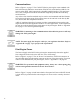
Communications Refer to Figure 1 on page 7. The 170PAX3™-Series print engine comes standard with both an Electronics Industries Association (EIA) RS-232 serial interface (DB-25 Connector) and an IEEE 1284 Centronics®-compatible parallel interface. The serial interface is also configured for both RS-422/RS-485 single drop and RS-485 multi-drop serial interfaces. Any of these four interface methods may be used to send commands and label formats from a host to the print engine.
DB-25 SERIAL INTERFACE CONNECTOR DB-15 APPLICATOR INTERFACE CONNECTOR PARALLEL INTERFACE CONNECTOR PARALLEL INTERFACE CONNECTOR DB-15 APPLICATOR INTERFACE CONNECTOR AC POWER CONNECTOR LEFT HAND PAX PRINT ENGINE DB-25 SERIAL INTERFACE CONNECTOR AC POWER CONNECTOR RIGHT HAND PAX PRINT ENGINE Figure 1.
8
Media & Ribbon Loading If you have a right hand print engine (printed labels are presented on the right hand side of the unit), refer to Figure 2 while performing the procedure shown below. If you have a left hand unit (printed labels are presented on the left hand side of the unit), refer to Figure 3 on page 10. 1. Load the media on the media supply reel of the applicator (refer to the applicator’s user’s manual). 2.
5. Ensure the media is aligned within the print path then close the printhead assembly (C) by rotating the printhead lock lever (D) until it latches onto the locking pin (E). 6. Secure the pinch roller (F) in position by pressing down on the top of the pinch roller latch (G) until the assembly snaps closed. 7. Position the outer media edge guide (B) so it just touches the outer edge of the media. 8. Raise the peel roller latch (I) and the peel roller assembly (J) will pivot down to a vertical position. 9.
10. Rotate the peel roller assembly (J) up until it latches closed. 11. Thread the backing material under the lower guide post (M) and around the take-up spindle of the applicator (refer to the applicator’s user’s manual). Ribbon Loading To load ribbon, refer to Figure 4 on page 12 (for right-hand units) or Figure 5 on page 13 (for left-hand units). NOTE: Do not load ribbon if the print engine is to be used in the direct thermal mode.
PAUSE DATA MEDIA RIBBON ERROR POWER PREVIOUS NEXT PAUSE FEED SETUP/EXIT CANCEL CALIBRATE O N Q OPEN D P C E Figure 4. Ribbon Loading (Right-Hand Units) Left Hand Units 1. Push the ribbon roll onto the supply spindle (N) as far as it will go, so the ribbon feeds as shown in Figure 5 on page 13. 2. Install an empty ribbon core onto the ribbon take-up spindle (O). 3. Open the printhead assembly (C) by unlatching the print- head lock lever (D) from the locking pin (E). 4.
PAUSE DATA MEDIA RIBBON ERROR POWER PREVIOUS NEXT PAUSE FEED SETUP/EXIT CANCEL CALIBRATE O N Q D OPEN P C E Figure 5. Ribbon Loading (Left-Hand Units) Removing Used Ribbon To remove used ribbon: 1. Open the printhead assembly (C) by unlatching the lock lever (D) from the locking pin (E). 2. Remove the ribbon between the upper ribbon guide roller (Q) and the ribbon takeup spindle (O). 3. Remove the used ribbon and the core together from the ribbon take-up spindle (O). 4.
14
Media Sensor Position Reflective Media Sensor Some types of media have black marks printed on the underside of the backing material that act as “Start of Label” indicators. These black marks are sensed by the reflective media sensor mounted to the lead screaw. The position of this sensor is not adjustable. If you are using this type of media, refer to the “Print Engine Specifications” on page 63 of this guide for information about black mark requirements.
16
Print Engine Operation Power On/Off Switch The Power On/Off Switch is located just to the left (or right) of the print engine’s control panel (see Figure 7 on page 18). When this switch is placed in the ON (1) position, the POWER light goes ON and the print engine automatically performs a Power On Self Test (POST). The Liquid Crystal Display validates the steps in the self test. NOTE: Refer to “Troubleshooting” on page 49 if the print engine stops due to failing a test in the Power On Self Test.
Table 1: Control Panel Key Description (Continued) Key Function • Scrolls back to the previous parameter. • Press and hold to quickly go backward through parameter sets. • Scrolls forward to the next parameter. (Saves any changes you’ve made in the configuration and calibration sequence.) • Press and hold to quickly advance through parameter sets. Enters and exits the configuration mode. These keys change the parameter values. They are used in different ways depending on the parameter displayed.
Control Panel Indicator LEDs LEDs on the front panel are a quick indication of the print engine’s status (see Figure 7 on page 18). Table 2: Control Panel LED Description LED POWER ERROR RIBBON MEDIA DATA PAUSE Status Indication Off The print engine is off or power is not applied. On The print engine is on. Off Normal operation — no print engine errors. Flashing A print engine error exists. Check the display screen for more information.
20
Configuration & Calibration After you have installed the media and ribbon and the power-on self test (POST) is complete, the front panel display will show “PRINTER READY.” (If the print engine fails its POST, refer to “Troubleshooting” on page 49) You may now set print engine parameters for your application using the control panel. Not all choices pertain to all applications.
The default password value is 1234. The password can be changed using the ^KP (Define Password) ZPL II instruction. NOTE: Once the password has been entered correctly, it will not have to be entered again unless you leave and re-enter the programming mode using the SETUP/EXIT key. NOTE: You can disable the password protection feature so that it no longer prompts you for a password by setting the password to ØØØØ via the ^KPØ ZPL/ZPL II command.
Configuration and Calibration Sequence Table 3: Configuration and Calibration Description Press --- Display Shows Action/Explanation PRINTER READY Normal print engine operation. DARKNESS Adjusting Print Darkness Press the RIGHT BLACK OVAL key to increase darkness. Press the LEFT BLACK OVAL key to decrease darkness. Default: +10 Range: 0 to +30 Darkness settings are dependent upon a variety of factors including ribbon type, media, and the condition of the printhead.
Table 3: Configuration and Calibration Description (Continued) Press Display Shows MEDIA TYPE Action/Explanation Setting Media Type Press the RIGHT or LEFT BLACK OVAL key to display other choices. Default: Continuous Selections: Continuous, non-continuous This parameter tells the print engine the type of media you are using. Selecting continuous media requires that you include a label length instruction in your label format (^LLxxxx if you are using ZPL or ZPL II).
Table 3: Configuration and Calibration Description (Continued) Press Display Shows MAXIMUM LENGTH Action/Explanation Setting Maximum Length Press the RIGHT BLACK OVAL key to increase the value, press the LEFT BLACK OVAL key to decrease the value. Default: 39.0” (988 mm) Range: 2.0” (50 mm) to 39.0” (988 mm) in 1.0” (25.4 mm) increments Maximum length is used in conjunction with the calibration procedure.
Table 3: Configuration and Calibration Description (Continued) Press Display Shows INITIALIZE CARD Action/Explanation Initialize Memory Card CAUTION: Perform this operation only when it is necessary to erase all previously stored information from the optional memory card. Press the NEXT/SAVE key to bypass this function. 1. Press the RIGHT BLACK OVAL key to select “YES.” If your print engine is set to require a password, you will now be prompted to enter the password.
Table 3: Configuration and Calibration Description (Continued) Press Display Shows INIT FLASH Action/Explanation Initialize Flash CAUTION: Perform this operation only when it is necessary to erase all previously stored information from the FLASH memory. Press the NEXT/ SAVE key to bypass this function. 1. Press the RIGHT BLACK OVAL key to select “YES.” If your print engine is set to require a password, you will now be prompted to enter the password. enter the password and then press the NEXT/SAVE key.
Table 3: Configuration and Calibration Description (Continued) Press Display Shows SENSOR PROFILE Action/Explanation Sensor Profile Press NEXT/SAVE to skip this standard calibration procedure and continue with the media and ribbon calibration parameter which follows. Press the RIGHT BLACK OVAL key to initiate this standard calibration procedure and print a media sensor profile. See Figure 8.
Table 3: Configuration and Calibration Description (Continued) Press --- Display Shows Action/Explanation CALIBRATING PLEASE WAIT The print engine automatically adjusts the scale (gain) of the signals it receives from the media and ribbon sensors based on the specific media and ribbon combination you are using. On the sensor profile, this essentially corresponds to moving the graph up or down to optimize the readings for your application.
Table 3: Configuration and Calibration Description (Continued) Press Display Shows DATA BITS Action/Explanation Setting Data Bits other choices. Press the RIGHT or LEFT BLACK OVAL key to display Default: 7-bits Selections: 7-bits, 8-bits The data bits of the print engine must match the data bits of the host for accurate communications to take place. Set the data bits to match the setting being used by the host. NOTE: Must be set to 8 data bits to use Code Page 850. PARITY Setting Parity other choices.
Table 3: Configuration and Calibration Description (Continued) Press Display Shows NETWORK ID Action/Explanation Setting Network ID Press the LEFT BLACK OVAL key to move to the next digit position, press the RIGHT BLACK OVAL key to increase the value of the digit. Default: 000 Selections: 000 - 999 Network ID is used to assign a unique number to a print engine used in an RS422/RS-485 network. This gives the host the means to address a specific print engine.
Table 3: Configuration and Calibration Description (Continued) Press Display Shows FORMAT PREFIX Action/Explanation Format Prefix Character Press the LEFT BLACK OVAL key to move to the next digit position, press the RIGHT BLACK OVAL key to increase the value of the digit. Default: 5E (caret) Range: 00 - FF The print engine looks for this 2-digit hex character to indicate the start of a ZPL/ZPL II format instruction.
Table 3: Configuration and Calibration Description (Continued) Press Display Shows Action/Explanation Figure 9. Ribbon Tension Setting Chart Power-Up and Head Close Parameters MEDIA POWER UP Media Power-Up other choices. Press the RIGHT or LEFT BLACK OVAL key to display Default: Feed Selections: Feed, calibration, length, and no motion This parameter establishes the action of the media when the print engine is turned on. • Calibration: Recalibrates the media and ribbon sensors.
Table 3: Configuration and Calibration Description (Continued) Press Display Shows Action/Explanation Label Positioning Parameters BACKFEED Backfeed Sequence play other choices. Press the RIGHT or LEFT BLACK OVAL key to dis- Default: Default (90%) Selections: Default, after, before, 10%, 20%, 30%, 40%, 50%, 60%, 70%, 80%, off This parameter establishes when and how much label backfeed occurs after a label is removed or cut in the peel-off, cutter, and applicator modes.
Table 3: Configuration and Calibration Description (Continued) Press Display Shows Action/Explanation HEAD TEST COUNT Setting the Head Test Count Press the LEFT BLACK OVAL key to move to the next digit position, press the RIGHT BLACK OVAL key to change the value of the digit. Default: 0000 (disables the test) Range: 0000 to 9999 The print engine periodically performs a test of the printhead functionality, called a “printhead test” or “head test.
Table 3: Configuration and Calibration Description (Continued) Press Display Shows APPLICATOR PORT Action/Explanation Setting the Applicator Port key to display other choices. Press the RIGHT or LEFT BLACK OVAL Default: Off Selections: Off, mode 1, mode 2, mode 3, mode 4 Determines the action of the verifier port. • Off: The applicator port is off. • Mode 1: Asserts the ~END_PRINT signal low while the printer is moving the label forward.
Table 3: Configuration and Calibration Description (Continued) Press Display Shows RESYNC MODE Action/Explanation Setting the Resync Mode to display other choices. Press the RIGHT or LEFT BLACK OVAL key Default: Feed Mode Selections: Feed Mode, Error Mode This parameter determines how the print engine will react if the label synchronization is lost and the label top is not where expected. This is set by the applicator manufacturer and should not be changed unless the factory defaults have been reloaded.
Table 3: Configuration and Calibration Description (Continued) Press Display Shows REPRINT MODE Action/Explanation Setting the Reprint Mode to display other choices. Press the RIGHT or LEFT BLACK OVAL key Default: Disabled Selections: Disabled, Enabled When the Reprint feature is enabled, the “Reprint” input signal (Pin 6) on the applicator port is functional. When the input signal is asserted, the last label printed will be printed again. (This includes non-printing labels.
Table 3: Configuration and Calibration Description (Continued) Press Display Shows LCD ADJUST Action/Explanation LCD Display Adjustment Press the LEFT BLACK OVAL key to decrease the value (reduce brightness), press the RIGHT BLACK OVAL key to increase the value (increase brightness). Range: 00 to 19 This parameter allows you to adjust the brightness of your display if your display is difficult to read. FORMAT CONVERT Format Convert Press the RIGHT or LEFT BLACK OVAL key to display other choices.
Table 3: Configuration and Calibration Description (Continued) Press Display Shows IP PROTOCOLS* Action/Explanation IP Protocols other choices. Press the RIGHT or LEFT BLACK OVAL key to display Default: All Selections: All, gleaning only, RARP, BOOTP, DHCP, DHCP/BOOTP *Option Required IP ADDRESS* If “dynamic” was chosen in the previous parameter, this selection determines the method(s) by which the PrintServer II will receive the IP address from the server.
Table 3: Configuration and Calibration Description (Continued) Press Display Shows SAVE SETTINGS Action/Explanation Save Settings Press the RIGHT or LEFT BLACK OVAL key to display other choices. Default: Permanent Selections: Permanent, temporary, cancel, load defaults, load last save. This display appears when you attempt to exit the configuration mode. • Permanent: Permanently saves the changes, even when printer power is turned off.
42
Care & Adjustments Cleaning CAUTION: Use only the cleaning agents indicated. Zebra Technologies Corporation will not be responsible for damage caused by any other cleaning materials used on the 170PAX3-Series print engine. Table 4 provides a recommended cleaning schedule. Cleaning swabs saturated with 70% Isopropyl Alcohol are available from your Zebra distributor as a Preventive Maintenance Kit (part # 01429).
Figure 10. Sensor Locations (Right-Hand Unit Shown) Cleaning the Printhead and Platen Roller Inconsistent print quality, such as voids in the bar code or graphics, or light print may indicate a dirty printhead. Media movement problems may indicate a dirty platen. For optimum print quality, perform the following cleaning procedure after every roll of ribbon.
Figure 11. Print Engine Cleaning (Right-Hand Unit Shown) 1. Open the printhead assembly (C) by lifting the printhead lock lever (D) upward away from the locking pin (E), and remove the media and ribbon. 2. Brush, vacuum, or air blow any accumulated lint and paper dust away from the rollers. It is good practice to clean the various media, ribbon, and door-open sensors at this time. See Figure 10 on page 44. 3. Use a cleaning swab saturated with alcohol and wipe the print elements from end to end.
Toggle Positioning Proper Toggle positioning is important for proper print quality. The toggles should be positioned 1/4 of the width in from the media edges (see Figure 12 inset). To position the toggles, loosen the locking nuts (T) and slide them to the desired position on the toggle pivot shaft (U); then, tighten the locking nuts. NOTE: Perform the Printhead Pressure Adjustment which follows, and make sure the toggle pressure is even, otherwise the media may drift or the ribbon may wrinkle.
T U S R Figure 12.
48
Troubleshooting Power On Self Test A Power On Self Test (POST) is performed each time the print engine is turned ON. During this test, the front panel lights (LEDs) will turn ON and OFF to ensure proper operation. At the end of this self test, only the POWER LED will remain lit. Once the Power On Self Test is complete, the media is advanced to the proper resting position, as determined by the programmed Media Feed setting.
The following tables provide trouble symptoms, a diagnosis of specific causes, and a recommended action which should result in proper print engine operation. If you are in need of technical assistance, contact your equipment supplier. Power On Troubleshooting Table 6: Power On Troubleshooting Symptom Diagnosis Action All lights on, but nothing displays on the LCD, and the print engine locks up. Internal electronic or firmware failure. Call a service technician.
Table 7: Print Engine Troubleshooting (Continued) Symptom Diagnosis Action WARNING HEAD COLD ERROR light flashes. Print Engine continues to print. Printhead is not hot enough to print properly. Printing continues while printhead heats up. If error remains, environment may be too cold for proper printing. Relocate print engine to warmer area. Verify print quality. ERROR CONDITION HEAD ELEMENT BAD Experiencing print quality problems. Printhead element is bad or going bad.
Table 7: Print Engine Troubleshooting (Continued) Symptom Wrinkled ribbon. Diagnosis Action Ribbon fed through the machine incorrectly. See“Ribbon Loading” on page 11. Incorrect burn temperature. Set the burn temperature to the lowest possible setting for good print quality. Incorrect or uneven printhead pressure. Set the pressure to the minimum needed. See “Printhead Pressure Adjustment” on page 46. Media not feeding properly; “walking” from side to side.
Table 7: Print Engine Troubleshooting (Continued) Symptom Changes in parameter settings did not take effect. ZPL II was sent to the print engine, but not recognized. DATA light always OFF. or DATA light always flashing. Vertical image or label drift. Diagnosis Action Parameters are set incorrectly. Set parameters and save permanently. Cycle the print engine power OFF and back ON. Incorrect ZPL format sent to the print engine. Check for the ^MP command.
Print Engine Self Tests Introduction These self tests, illustrated on the following pages, produce sample labels and provide specific information that help determine the operating conditions for the print engine. Each self test is enabled by pressing a specific control panel key or combination of keys while turning the power switch ON. Keep the key pressed until the first indicator light turns OFF. The selected self test will automatically start at the end of the Power On Self Test.
CANCEL Key Self Test Press and hold the CANCEL key while turning the print engine power ON. Release the key anytime after the first front panel LED turns OFF. This self test prints a label that contains a listing of the print engine’s current configuration parameters stored in configuration (EEPROM) memory (refer to Figure 13). The configuration may be changed either temporarily (for specific label formats or ribbon and label stock) or permanently (by saving the new parameters in EEPROM memory).
PAUSE Key Self Test Press and hold the PAUSE key while turning the print engine power ON. Release the key anytime after the first front panel LED turns OFF. This self test is actually comprised of five individual test features: 1. The initial self test prints 15 labels at 2" (5.08 cm) per second, then automatically pauses the print engine. Each time the PAUSE key is pressed, an additional 15 labels print. 2. While the print engine is paused, alter the self test by pressing the CANCEL key once.
FEED Key Self Test Press and hold the FEED key while turning the print engine power ON. Release the key anytime after the first front panel LED turns OFF. NOTE: The CANCEL Key Self Test should be performed prior to this self test. Information on the printed configuration label can be used with the results of this self test to determine the best darkness setting for a specific media/ribbon combination. The labels printed during this print quality test depends on the dot density of the printhead.
FEED Key and PAUSE Key Press and hold these two keys while turning the print engine power ON. The print engine configuration will be temporarily reset to the factory default values. These values will be active until power is turned OFF. NOTE: If the factory default values are permanently saved, a media calibration procedure must be performed. You must also reset the head resistance value, and the verifier and applicator port settings to their required values (see “Configuration & Calibration” on page 21).
Table 8: Configuration Parameters (Continued) Parameter Controlled by Head Resistance (must match head resistance label value) Configuration or ZPL Verifier Port Configuration and ZPL Applicator Port Configuration and ZPL Start Print Signal Configuration and ZPL Resynch Mode Configuration and ZPL Ribbon Low Mode Configuration and ZPL Reprint Mode Configuration and ZPL Web Sensor Configuration and ZPL Media Sensor Configuration and ZPL Ribbon Sensor Configuration and ZPL Mark Sensor Co
Communications Diagnostics Test The following test cannot be performed until all configuration and calibration parameters have been set. For information, refer to “Configuration & Calibration” on page 21. NOTE: This test is performed via the control panel. Refer to “Setting the Communications Mode” on page 31. A typical printout from this test is shown in Figure 16. This label will be inverted when printed. Figure 16.
Options Your print engine can be equipped with the following options. Contact your equipment supplier for further information and pricing. Single In-line Memory Module (SIMM) An optional 8 MByte SIMM increases the graphic and font storage capacity of the print engine and/or increases the print length. As this is volatile memory, contents will be lost when the print engine is turned off.
62
Print Engine Specifications Printing Considerations Media Type (continuous, die-cut, or black mark) 172PAX3 173PAX3 Resolution 203 dots per inch (8 dots per mm) 300 dots per inch (12 dots per mm) Dot size 0.0049” x 0.0049” (0.125 mm x 0.125 mm) 0.0033” x 0.0039” (0.084 mm x 0.100 mm) First dot location (from inside media edge) 0.093” ±0.035” (2.4 mm ±0.89 mm) 0.093” ±0.035” (2.4 mm ±0.89 mm) Maximum print width 6.6” (168 mm) 6.
Ribbon Specifications Width (wound coated side out) 3.0” (76 mm) to 7.1” (180 mm) Standard length 984’ (300 m), 1476’ (450 m), 1969’ (600 m), and 2955’ (900 m) Roll size Inner core diameter / Maximum roll size 1.0” (25.4 mm) / 4.0” (101.
• Linear bar codes: Code 11, Code 39, Code 93, Code 128 with subsets A/B/C and UCC Case Codes, ISBT-128, UPC-A, UPC-E, EAN-8, EAN-13, UPC and EAN 2 or 5 digit extensions, Plessey, Postnet, Standard 2 of 5, Industrial 2 of 5, Interleaved 2 of 5, LOGMARS, MSI, and Codabar • Bar code ratios: 2:1, 7:3, 5:2, and 3:1 Communication Specifications • High-speed parallel interface, Centronics® compatible • High-speed serial interfaces: RS-232C and RS422 with DB25S (Female) connector RS-485 multi-drop capabilit
Font Matrices for 8 dot/mm (203 DPI) Printhead Character Size (in dots) 1 U-L-D 0.044 0.029 33.90 1.13 0.75 1.33 B 11 7 2 U 0.054 0.044 22.60 1.38 1.13 0.89 C, D 18 10 2 U-L-D 0.088 0.059 16.95 2.25 1.50 0.67 E 28 15 5 OCR-13 0.138 0.098 10.17 3.50 2.50 0.40 F 26 13 3 U-L-D 0.128 0.079 12.71 3.25 2.00 0.50 G 60 40 8 U-L-D 0.295 0.236 4.24 7.50 6.00 0.17 H 21 13 6 OCR-A 0.103 0.093 10.71 2.63 2.38 0.42 GS 24 24 0 SYMBOL 0.
Physical Dimensions Height 11.8” (300 mm) Width 9.6” (245 mm) Depth 17.0” (432 mm) Weight 32 lbs. (14.5 kg) NOTE: For installation information, refer to “Appendix E” on page 85. Electrical Specifications • Dual 32-bit RISC and CISC microprocessors • Universal Power Supply with power-factor correcting 90-264 VAC, 48-62 Hz • Power consumption: Idle = 19 W, Printing = 220 W (printing Pause Test label at speed A) • Agency approvals: UL 1950 3rd edition, CSA 22.
68
Appendix A AC Power Cord Requirements Since many areas of the world have specific power requirements, an AC Power Cord may not be included with your print engine. Refer to Figure 17. A power cord must be provided by you that meets your local electrical requirements. WARNING! For personnel and equipment safety, always use a three-prong plug with an earth ground connection to the AC Power Source. AC Power Cord Specifications: • The overall length must be less than 9.8 feet (3 m).
Power Fuse Replacement The print engine uses a metric-style fuse (5 x 20 mm IEC) rated for 5 Amps at 250 Volts that bears the certification mark of a known international safety organization (see Figure 18 on page 69). The power entry module comes with two approved fuses in the fuse holder; one is “incircuit” and one is provided as a “spare.” To replace a fuse, follow this procedure and refer to Figure 19: 1 Turn off the print engine and unplug the power cord from the back of the print engine.
Shipping To ship the Zebra 170PAX3-Series print engine, remove all ribbon and media and make sure the printhead is closed for shipment. Carefully pack the print engine in a suitable container to avoid damage during transit. Whenever possible, use the original “carton within a carton” packing materials from the factory. A shipping container (PN:49367) can be purchased from Zebra Technologies Corporation if the original packaging is lost or destroyed.
72
Appendix B Print Engine Communications Interface Technical Information System Considerations Communications Code — The print engine sends and receives American Standard Code for Information Interchange (ASCII). This code consists of 128 characters (256 for Code Page 850) including upper and lower case letters, numbers, punctuation marks, and various control codes.
WARNING! Connecting a data communications cable while the power is ON may damage the PAX3 print engine. RS-232/RS-422/RS-485 Serial Data Port The connections for these standard interfaces are made through the DB25 Female connector on the rear panel. Refer to Table 8. For all RS-232 input and output signals, the print engine follows both the Electronics Industries Association’s (EIA) RS-232 and the Consultative Committee for International Telegraph and Telephone (CCITT) V.
RS-232 Interconnections — The print engine is configured as Data Terminal Equipment (DTE). Figure 20 illustrates the connections required to interconnect the print engine with the standard 9-pin serial port connector on a PC. Figure 21 illustrates the internal connections of the print engine’s RS-232 connector. NOTE: If using a 9-pin to 25-pin adapter plug attached to the computer, use a null modem cable between the adapter plug and the print engine.
RS-422/RS-485 Interconnections — The print engine may be connected to a host by a RS-422/RS-485 interface. The DB25 Female connector on the rear of the print engine uses specific pins for this purpose. Figure 22 illustrates the required cable wiring for interconnecting to the print engine’s DB25 connector. Figure 23 illustrates the internal connections of the print engine’s RS-422/RS-485 connector. Male DB-25 to Printer Shield Signal Ground Ref.
Centronics-Compatible Parallel Data Port A standard 36-pin Centronics-compatible parallel connector is available at the rear of the print engine for connection to the data source. The standard RS-232 port will not accept data when the parallel port is enabled. The parallel interface receives data from the data source but cannot send back print engine status information over this port.
Cabling Requirements Data cables must be fully shielded and fitted with metal or metallized connector shells. Shielded cables and connectors are required to prevent radiation and reception of electrical noise. To minimize electrical noise pickup in the cable: • Keep data cables as short as possible. • Do not bundle the data cables tightly with the power cords. • Do not tie the data cables to power wire conduits.
Table 10: DB-15 Connector (Printer to Applicator) (Continued) Pi n# Signal Name Signal Type Functional Description 5 PAUSE Input To toggle the current PAUSE state, this input must be asserted LOW for 200 milliseconds, or until the SERVICE REQUIRED output (pin 10) changes state. 6 REPRINT Input If the REPRINT feature is enabled – this input must be asserted LOW to cause the print engine to reprint the last label.
Figure 24.
Appendix C ASCII Code Chart HEX CHAR HEX CHAR HEX CHAR HEX CHAR 00 01 02 03 04 05 06 07 08 09 0A 0B 0C 0D 0E 0F 10 11 12 13 14 15 16 17 18 19 1A 1B 1C 1D 1E 1F NUL SOH STX ETX EOT ENQ ACK BEL BS HT LF VT FF CR SO SI DLE DC1 DC2 DC3 DC4 NAK SYN ETB CAN EM SUB ESC FS GS RS US 20 21 22 23 24 25 26 27 28 29 2A 2B 2C 2D 2E 2F 30 31 32 33 34 35 36 37 38 39 3A 3B 3C 3D 3E 3F space ! “ # $ % & ‘ ( ) * ++ , .
82
Appendix D Adjusting Darkness For “In-Spec” Bar Codes All direct thermal and thermal transfer materials do not require the same darkness setting. The best way to check for proper darkness is to use a bar code verifier that actually measures bars/spaces and will calculate the print contrast. Without the assistance of a verifier, your eyes and/or the system scanner are the best bet for choosing the optimal darkness setting.
“In-Spec” The “in-spec” bar code can only be confirmed by a verifier, but it should exhibit some very visible characteristics. The normal bar code will have complete, even bars and clear, distinct spaces. The rotated bar code will also have complete bars and clear distinct spaces. Although it may not look as good as a slightly dark bar code, it will be “inspec.” In both normal and rotated styles, small alphanumeric characters will look complete. Figure 25.
Appendix E Installation Information Ventilation openings of the print engine mounting enclosure shall be provided by the installer to remove heat and ensure uninterrupted, trouble-free operation of the print engine. Ambient air temperature surrounding the print engine must not exceed 40 degrees Centigrade or 104 degrees Fahrenheit.
Figure 27. Front View of Right-Hand Printer NOTE: Mounting hole locations are identical for both the right hand and left hand print engines. Clearance at the rear panel of the electronics enclosure must provide ample space for electronic connectors and dressing of the following cables: IEC power cord, serial and/ or parallel host communication cable, optional host communication cable (Coax, Twinax, Ethernet), and the discrete signal (applicator) interface cable.
Figure 28.
88
Glossary alphanumeric Indicating letters, numerals, and characters such as punctuation marks. backfeed When the print engine pulls the media and ribbon (if used) backward into the print engine so that the beginning of the label to be printed is properly positioned behind the printhead. Backfeed occurs when operating the print engine in tear-off or applicator mode. bar code A code by which alphanumeric characters can be represented by a series of adjacent stripes of different widths.
firmware This is the term used to specify the print engine’s operating program. This program is downloaded to the print engine from a host computer and stored in FLASH memory. Each time the print engine power is turned on, this operating program starts. This program controls when to feed the media forward or backward, when to print a dot on the label stock, when to activate the cutter, etc. flash memory FLASH memory is nonvolatile and will maintain the stored information intact when power is off.
ribbon A band of material consisting of a base film coated with wax or resin “ink”. The inked side of the material is pressed by the printhead against the media. The ribbon transfers ink onto the media when heated by the small elements within the printhead. Zebra ribbons have a coating on the back that protects the printhead from wear. tag A type of media having no adhesive backing but featuring a hole or notch by which the tag can be hung on something.
92
Index A AC Power ...............................................6 Adjustments Printhead Pressure Adjustment ......46 Toggle Positioning .........................46 Applicator Interface Connector ...........78 Applicator Port, setting ........................36 ASCII Code Chart ................................81 B Backfeed Sequence ..............................34 Bar Codes List of available .............................64 Printing a list ..................................25 Baud Rate ......................
Images, printing a list ...........................25 Initializing the card ..............................26 Initializing the FLASH ........................27 In-Spec Bar Codes, adjusting darkness 83 Installation Information .......................85 Introduction ..........................................54 IP Address, setting ...............................40 IP Protocols, setting .............................40 IP Resolution, setting ...........................39 L Label Positioning Parameters ..........
Printhead Pressure Adjustment ............46 Printing Considerations ........................63 Protocol, setting ...................................30 R Reflective Media Sensor ......................15 Reporting Damage .................................5 Reprint Mode, setting ..........................38 Resync Mode, setting ...........................37 Ribbon Loading ..........................................11 Removal .........................................13 Ribbon Low Mode, setting .................
96
Zebra Technologies Corporation Zebra Technologies Europe Limited 333 Corporate Woods Parkway Vernon Hills, Illinois 60061-3109 U.S.A. Zebra House The Valley Centre, Gordon Road High Wycombe, Buckinghamshire HP13 6EQ, UK Phone Number: Fax Number: Phone Number: Fax Number: +1 847. 634.6700 +1 847. 913.8766 Customer Order # 49579L Manufacturer Order # 49579LB Rev.