P310 Maintenance Manual C A R D P R I N T E R P R O D U C T S Manual No. 980264-001 ©2001 Zebra Technologies Corporation Rev.
FOREWORD This manual contains service and repair information for P310 Card Printers manufactured by Zebra Technology Corporation, Camarillo, California. The contents include maintenance, diagnosis and repair information. TECHNICAL SUPPORT For technical support, users should first contact the distributor that originally sold the product—phone +1 (800) 344 4003 to locate the nearest Eltron Products Distributor. Eltron Products offers the following: U.S.A Europe Internet e-mail cardsup@eltron.
This information is not intended as a license to practice or infringe on the patents of this company or others. Zebra Technology Corporation reserves the right to modify, update or revise this information at any time without notice. TRADEMARKS Eltron is a trademark of Zebra Technology Corporation. All other marks are trademarks or registered trademarks of their respective holders.
Table of Contents CHAPTER 1 GENERAL DESCRIPTION PRINTER DESCRIPTION . . . . . . . . . . . . . . . . . . . . . . . . . . 1-1 Options · · · · · · · · · · · · · · · · · · · · · · · · · · · · · · · · · · · · · 1-2 Major Elements . . . . . . . . . . . . . . . . . . . . . . . . . . . . . . .
Motor Control Circuitry · · · · · · · · · · Status Circuitry · · · · · · · · · · · · · · Serial and Parallel Port Circuitry · · · · · · USB Port Circuitry (Optional) · · · · · · · Magnetic Stripe Encoder Circuitry (Option)· Smart Card Circuitry (Option) · · · · · · · Operator Panel Circuitry · · · · · · · · · · Power Regulator Circuitry · · · · · · · · · · · · · · · · · · · · · · · · · · · · · · · · · · · · · · · · · · · · · · · · · · · · · · · · · · · · · · · · · · · · · · · · · · · · · · · · · ·
Print Head Tilt Adjustments · · · · · · · · · · · · · · · · · · · · · · · · · · · 6-9 Print Head Peel Bar Position Adjustment · · · · · · · · · · · · · · · · · · · · 6-12 Image Centering · · · · · · · · · · · · · · · · · · · · · · · · · · · · · · · · 6-13 APPENDIX A TEST SOFTWARE INSTALLATION . . . . . . . . . . . . . . . . . . . . . . . . . . . . . . . A-1 OPERATION . . . . . . . . . . . . . . . . . . . . . . . . . . . . . . . .
Figure 4-1. Problems Duplicated by a Test Print. . . . . . . . . . . . . . . 4-2 Figure 4-2. Interface Diagnostic Flow. . . . . . . . . . . . . . . . . . . . . 4-4 Figure 5-1. Rear Case Fasteners. . . . . . . . . . . . . . . . . . . . . . . 5-3 Figure 5-2. Front Case Removal. . . . . . . . . . . . . . . . . . . . . . . 5-4 Figure 5-3. Bottom Plate Removal. . . . . . . . . . . . . . . . . . . . . . 5-5 Figure 5-4. Bottom Plate and Power Supply. . . . . . . . . . . . . . . . . 5-6 Figure 5-5.
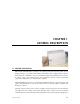
CHAPTER 1 GENERAL DESCRIPTION 1.1 PRINTER DESCRIPTION Eltron® Model P310 printers offer low cost solutions to those that need to print, encode magnetic stripes, or program smart plastic cards. Eltron offers imaging ribbon varieties that include dye sublimation color, dye sublimation black, thermal transfer monochrome in various colors, and scratch-off gray. Dye sublimation ribbons include panels that support the application of a clear protective varnish.
CHAPTER 1 objects. For those who wish to create card graphics from their software applications, the units ship with both Windows 95/98 and NT drivers. Both drivers support True Type fonts. 1.1.1 Options Plastic card varieties include Smart Cards and cards with Magnetic Stripes. Because not everyone may want to use associated capabilities, integration of related hardware is offered as options. Encoders can place data on either high- or low-coercivity stripes.
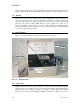
CHAPTER 1 adjust the feeder for other thicknesses as well. The Card Feed Hopper, has an attached Card Weight that positions itself on top of a stack of cards in the Hopper. This added weight increases the grip of the card feed rollers and assures reliable card feeds throughout cartridge-full to cartridge-empty conditions. 1.2.2 Cleaning Roller Cards transitioning between the Card Input Hopper and the Printer (or Smart Card Station) travel through a pair of rollers.
CHAPTER 1 1.2.5 Magnetic Stripe Encoder (Option) Printers equipped with Magnetic Stripe Encoders fully support the encoding of cards with magnetic stripes. This includes several encoding formats. Read-After-Write checking occurs with each encoding to assure a reliable result. After receipt of related data, encoding of all three tracks occurs in a single pass through the encoder.
CHAPTER 1 1.4 CAUTIONARY NOTES Exercise reasonable care when servicing P310 printers, as follows: Other than prescribed operator maintenance, only qualified personnel should remove the case or otherwise attempt to repair this equipment. Eltron offers product training to those wishing to service this equipment. Servicing personnel must avoid touching exposed circuitry. Inputs to the Power Supply operate at power line voltages. Any removal of protective insulation can expose dangerous voltages.
CHAPTER 1 1.5 PACKAGING CONSIDERATIONS The factory-supplied shipping carton contains the Printer placed inside a protective ESD (Electrostatic Discharge) bag and suspended in form-fitting end cushions made from a foam material. These are the only materials approved for P310 shipments. Any shipping damage may not be covered by either the product warranty or the carrier if the printer is shipped with packaging materials that do not meet associated shipping standards.
CHAPTER 2 INSTALLATION AND OPERATION This chapter includes information on the following: • Unpacking • Installation • Controls and Indicators • Card and Ribbon Loading Similar descriptions also appear in the associated User’s Guide and other manuals shipped with the printer. The intent here is to make this manual as complete as possible with a minimum of references to other manuals. Operations related to software applications and the Windows Driver do not appear in this manual.
CHAPTER 2 2.1 INSTALLATION 2.1.1 Unpacking Figure 2-1 shows the carrier-approved packaging materials used for shipping and how these items fit within inside and outside cartons. Note that customers should keep these materials on hand for future shipping needs. The product warranty may not cover a printer damaged during a shipment if the printer is packaged using unapproved shipping materials. If necessary, users can order replacements before shipping the Printer. Figure 2-1.
CHAPTER 2 2.1.2 Tape and Packing Removals Figure 2-2 shows the tape and packing material that requires removal prior to printer operation. Figure 2-2. Tape and Packing. 2.1.3 Card Input Hopper Installation Figure 2-3 shows Installation of the Card Input Cartridge. Figure 2-3. Card Input Cartridge Installation. 980264-001 Rev.
CHAPTER 2 2.1.4 Card Catcher Installation Figure 2-4 shows the installation of the Card Catcher. Figure 2-4. Card Output Hopper. 2.1.5 Cleaning Roller Cartridge Preparation Figure 2-5 shows how to install the Cleaning Roller into the Cleaning Roller Cartridge. Figure 2-5. Cleaning Roller Installation. 2-4 980264-001 Rev.
CHAPTER 2 2.1.6 Cleaning Roller Tape Removal Figure 2-6 shows removal of the tape protecting the tacky surface. Figure 2-6. Cleaning Roller Cartridge Preparation. 2.1.7 Cleaning Roller Cartridge Installation Figure 2-7 shows where the Cleaning Roller Cartridge fits into the Printer. Figure 2-7. Cleaning Roller Cartridge Installation. 980264-001 Rev.
CHAPTER 2 2.1.8 Location Concerns Users should avoid dusty locations. Until ready for use, keep ribbon and card media in their cartons. Select a location that offers easy access to all sides plus an unrestricted air flow. Avoid locations that experience extremes in temperature and/or humidity. 2.1.9 Attaching Cables Figure 2-8 shows the Rear Panel of a Printer.
CHAPTER 2 USB Concerns (USB Specification Rev. 2.0) 1. USB-Equipped Host Computers have Hub connection(s) and software that supports the connections for up to 127 devices (either USB Functions or USB Hubs), all hot swapable. 2. Hubs implement one connection path upstream to, or toward, the Host and typically several Ports for downstream Functions and/or other Hub connections. Functions refer to Printers, Mice, Keyboards, etc. 3. USB Cables each have both A- and B-type connectors.
CHAPTER 2 2.1.10 Parallel an Serial Cable Diagrams Figure 2-10 shows the cable wiring. HOST STROBE DATA 0 DATA 1 DATA 2 DATA 3 DATA 4 DATA 5 DATA 6 DATA 7 ACK/ BUSY PAPER ERR. READY INIT ERROR/ N/A N/A N/A SIG. GND SIG. GND SIG. GND SIG. GND SIG. GND SIG. GND SIG. GND DB-25 Pin No. 1 2 3 4 5 6 7 8 9 10 11 12 13 14 15 16 17 18 19 20 21 22 23 24 25 DB-25 Pin No.
CHAPTER 2 2.2 OPERATION 2.2.1 Controls and Indicators Figure 2-11 shows the push-button switch and LEDs (light emitting diodes) that appear on the front of the Printer. The Power Switch resides on the rear. Users press the Printer Button to reinitialize P310 printers. Users also press this button to signal when a user intervention has corrected an Alert condition that has suspended operations. Figure 2-11. Controls and Indicators 2.2.
CHAPTER 2 2.2.3 Print Head Release and Latch Levers Figure 2-12 shows the Release and Latch levers for the Print Head. Users open the Cover and raise the Print Head during manual Cleaning Procedures, removal of card jams, and ribbon loads. Figure 2-12. Print and Lamination Head Latch and Release Levers. 2-10 980264-001 Rev.
CHAPTER 2 2.2.4 Ribbon Loading Figure 2-13 shows the loading of ribbons. Note that by keeping the Power ON during Ribbon Loads, a suspended operation resumes automatically with the Print Head latch-down that completes Ribbon Loading. Step 1. Remove the ribbon from its packaging and the material holding the supply and take up rolls together. Step 2. Unroll enough ribbon from the supply roll to bridge the space between the supply and take up spindles of the printer. Step 3.
CHAPTER 2 2.2.5 Card Gate Adjustment Figure 2-14 shows the Card Gate Adjustment Lever with arrows that show the directions of travel. Step 1. Set the Card Gate Thickness Lever to match the thickness of the cards. Note that lever positions closer to the back of the printer open the Card Feed Gate for thicker cards. Step 2. If during operation cards either fail to feed or multiple card feeds occur, check the setting of the Card Gate Adjustment Lever.
CHAPTER 2 2.2.6 Loading Card Input Hopper Figure 2-15 shows the Card Input Hopper actions necessary to replenish cards. Step 1. Press down on Release Tab, and rotate Hopper to open position. Step 2. Place cards in Hopper with printed side facing right (facing up with hopper closed). Cards with Magnetic strips normally get installed with down-facing stripes, but some Encoder installations support up-facing stripes for printing on side with stripe.
CHAPTER 2 2.2.7 Starting the Cleaning Cycle As noted in Section 2.2, the right two panel LEDs flash when the time for a Cleaning Cycle arrives. Until performed, normal operations cannot continue. While the flashing occurs at card count intervals determined by a printer command (see Programmer's Manual), users can initiate a Cleaning Cycle at any time. Each Cleaning Cycle resets the card counter that triggers the time-to-clean signal. Refer to Figure 2-16, and proceed as follows: Step 1.
CHAPTER 3 THEORY OF OPERATION This chapter includes three major topics: • Color Fundamentals • Card Path Elements • Circuit Descriptions 3.1 COLOR FUNDAMENTALS The following offers readers a perspective on how imaging occurs in various systems, with a particular emphasis on card printers, their interaction with other system elements, and a comparison of techniques. Color refers to the hues people see. This refers to the visual spectrum.
CHAPTER 3 Saturated colors are colors in their purest state. This means they contain no white (as in pastels) or black (contrast reduction) components. A so-called trained observer can discern about 450 fully saturated shades. When these colors are diluted by black, the number of discernable shades diminishes. However, white dilutions increase the number of colors discernible. In Card Printers, images result from two types of ribbon coatings—dye and resin.
CHAPTER 3 Offset printing and Dye Sublimation can produce a substantial range of colors within just one dot. Color Monitors produce their range of colors using a red, green, and blue (RGB) three-dot matrix. Scanners and digital cameras employ charge-coupled devices (CCDs) that capture and deliver RGB components.
CHAPTER 3 Not all images require high dot densities. The need for high dot density decreases as the viewing distance increases. For example, a large roadside sign may require separations screened at only four lines-per-inch. Such a sign would appear like a mosaic of CMYK dots if viewed from too close a distance. Note that press men use lines per inch instead of dots per inch, because they image color separations through screens to generate dot-based images from continuous-tone images.
CHAPTER 3 color of the print media. In monitors, maximum intensities (maximum additions) result in white, and minimum intensities produce black. Because light reflected from print media depends on ambient lighting, users may get darker images from a printer than they see on their monitor, where a brightness setting exists. Print illumination (generally from room or outdoor lighting) affects color for all printed images.
CHAPTER 3 green, and blue CRT phosphors. Moreover, devices with a brightness control allow a wide range of image intensities. Active Matrix Displays generate images from a back-lighted grid that activates red, green, and blue LCD pixel elements. For paper, and other print media, gloss affects brightness, and Black Body Temperature affects hue. More issues arise with the addition of a color scanner to a system. These devices also differ between manufacturers.
CHAPTER 3 3.2 PRINTING Color imaging requires three passes of Card media underneath the Print Head. Card media shuttles back and forth across the print head during this process. The ribbon feeds between the image head and the card media and during printing advances from its supply to its take-up reels in step with an advancing Card. Heat, when generated at an image head element, transfers ribbon dye in a measured quantity or fully saturated resin onto the print media.
CHAPTER 3 3.3 CARD PATH ELEMENTS The upper part of Figure 3-1 points out the rollers that transport Cards. The lower part identifies the sensors that detect the various events that occur during card printing. These LED-Photo transistor sensors signal reception of cards from the Card Feeder, ribbon initialization, Head Up and Head Down Print Head cam positions, and whether the Print Head is open or Latched. The Flag Sensor signals incremental ribbon advances.
CHAPTER 3 Card Input Hopper Ribbon Take Up Cleaning Roller Print Head Magnetic Encoder (Option) To Card Catcher Card Path Smart Card Station (Option) Transport and Platen Rollers Ribbon Sensor Flag Sensor Print Head Latched Sensor C a r d Fe e d Roller Card Sensor To Card Catcher Cam Follower (Raises Encoder Station Pinch Roller) Head Up/Down Sensors Daughter Board Figure 3-1. Card Path Elements. 980264-001 Rev.
CHAPTER 3 3.4 CIRCUIT DESCRIPTIONS As shown in Figure 3-2, P310 Printers have the following circuits: • Print Head Circuiry • Motor Control Circuitry • Status Circuitry • Interface Circuitry • Operator Panel Circuitry • Optional Encoder and/or Smart Card Circuitry If possible, spend some time with this figure. The intent is to offer another perspective to descriptions given in other parts of the manual. Most of the circuitry resides on the CPU Board.
CHAPTER 3 MICROCONTROLLER Clock (32.
CHAPTER 3 3.4.1 Print Head Circuitry Figure 3-3 shows the Print Head circuitry. Note that one part lies on the CPU board, and another part lies on the Print Head Assembly. After a reset, which occurs at initialization, the processor places 32 bits of image data on the data bus. This data loads into the U12 through U15 registers with activation of the CS HEAD signal. This signal also clears the U9 a and b flip-flops and the U11 counter.
CHAPTER 3 CTN PRINT HEAD ASSEMBLY R672 R1 Thermistor GND DATA4 0 1 3 2 5 4 6 DATA2 STROBE STROBE HEADCLK/ LATCH* RESET/ GND DATA0~31 D0~7 QA U15 U9a D Q CK QH U9b CK D Q CLR Q SH-LD/ CK CLK TETE Q CLR 14.
CHAPTER 3 3.4.2 Motor Control Circuitry Figure 3-4 shows the Motor Control Circuitry. Stepper Motor inputs PHASE 1 through PHASE 4 determine the direction of rotation and stepping verses fractional stepping. The micro controller loads data into registers U26 and U27 through activation of CS MOT. This data determines the operation of U28. U28 then generates the associated phase signals. For each of its operations, U28 also requires specific reference voltages.
CHAPTER 3 U26 Stepper Motor Q1~8 D16~23 C OC D16~31 U28 U27 REF1 Q1~2 I01 I11 PH1 PH2 I12 I02 D24~31 Q3~8 CS MOT (CS7/) RESET RC1 C OC GND RC2 Vcc U29 Q1 Q2 Q3 Q4 Q5 Q6 CLK Q7 OC D24~31 CS_IO R_W/ REF2 PHASE 1 PHASE 2 PHASE 3 PHASE 4 J10 SENSE1 COMP.
CHAPTER 3 3.4.3 Status Circuitry Figure 3-5 shows the Status circuitry. This circuitry allows the Micro Controller to monitor all the operational status of the basic printer. On the left are Card, Ribbon panel, Flag, Head Latch, and Head up/Down Sensors. Below these appear the Print Head Temperature Sensing Thermistor. Programmable resistors inside U20 set the threshold levels of U17 analog comparators a through d and the LED intensity of the Card and Ribbon Sensors.
CHAPTER 3 J10 E_FILM Vcc R FILM E_SYNCH _ U17d R SYNCH E_COLOR + _ U17a R_COLOR + Vcc E_BRACKET See motor Circuitry _ U17b VDD MEASURE + R FILM T SYNCHRO COULEUR PUISS+24V TEMPERATURE D_SMART SW_TETE_UP SW_TETE_DOWN Vcc R_BRACKET _ Vcc U17c + DOT HS Recept IN2 IN3 INIT SELECTIN/ AUTOFD STROBE/ Vcc R_W/ D1 Q1 D2 Q2 D3 Q3 D4 Q4 D24~31 D5 Q5 D6 Q6 D7 Q7 D8 Q8 CLK OC U32 D1 Q1 D2 Q2 D3 Q3 D4 Q4 D16~23 D5 Q5 D6 Q6 D7 Q7 D8 Q8 CLK OC U31 CS_IO J3 CTN Print Head Thermister U20 Vcc REFERENCE U
CHAPTER 3 3.4.4 Serial and Parallel Port Circuitry Figure 3-6 shows the Parallel and Serial Port circuitry. Note that a Serial Host Port is optional. When used, the Micro Controller supplies the Serial Port data signals. U18 is a receiver/transmitter that has a built-in charge pump for outputs that require ±10-volt swings. Note that U18 connects to two port connectors. For these printers, only the host connection is used.
CHAPTER 3 Vcc Vdd+24V J8 8 7 6 5 4 3 2 1 J5 EXT2 EXT3 U18 C2+ C1+ TXD1 RXD1 TXD2 RXD2 C1T1 IN R2 OUT C2T1 OUT R2 IN T2 IN R1 OUT T2 OUT R1 IN U- U+ 5 4 3 2 1 Vcc 100nf 1k D16~23 CSRead/ R_W/ CS// CSWrite DIR STROBE// CSWrite/ IT D24~31 D24~31 CSWrite/ U40 D1 Q1 D2 Q2 D3 Q3 D4 Q4 D5 Q5 D6 Q6 DIR D7 Q7 D8 Q8 SORTIE CLK OC U39 D1 Q1 D2 Q2 D3 Q3 D4 Q4 D5 Q5 D6 Q6 D7 Q7 D8 Q8 CLK OC U38 D1 Q1 D2 Q2 D3 Q3 D4 Q4 D5 Q5 D6 Q6 D7 STROBE// Q7 D8 Q8 CS Read/ CLK OC CS 1 U41 1A1 1Y1 1A2 1Y2 1A3 1Y
CHAPTER 3 3.4.5 USB Port Circuitry (Optional) Figure 3-7 shows the USB circuitry. This circuitry resides on a separate board that attaches to the same connector that the Magnetic Stripe Encoder Connector can use. For configurations that have both the USB Board and a Magnetic Stripe Encoder, this board supplies a connector (J1) that carries through the connector signals. J1 resides just above the non-USB connection point. The USB Chip (U2) includes hard wired programming that deals with the USB Protocols.
CHAPTER 3 3.4.6 Magnetic Stripe Encoder Circuitry (Option) Figure 3-8 shows the Magnetic Strip Encoder elements, consisting of the board, Read/Write heads and associated cables. The Encoder Board is a purchased part that Eltron Card neither designs nor assembles. Note that the USB and Encoder Boards use the same CPU Board connector. With both options installed, the Encoder Board connector attaches to an identical USB Board connector that feeds through the required signals. J2 1 . . .
CHAPTER 3 3.4.7 Smart Card Circuitry (Option) Figure 3-9 shows the Smart Card circuitry. Note that J05 interfaces with the Main Circuit Board of the printer, and that the DB-9 connector interfaces with the user’s Smart Card Programming Device. Also note that the Smart Card Station has two sets of contacts—supporting two Smart Card Chip placements.
CHAPTER 3 SMART CARD DOCKING BOARD J01 Smart Card Chip Contacts Shown Facing Up J9 Vdd+24V 8 EXT1 5 Vcc 4 CDE SMART 3 D SMART 2 C5 C6 C7 C8 Vcc RST CLK RFU C4 C3 C2 C1 C5 C6 C7 C8 C8 C7 C6 C5 C1 C2 C3 C4 GND Vpp I/O RFU C1 C2 C3 C4 C1 C2 C3 C4 Top View with Contacts Facing Down C5 C6 C7 C8 C1 C6 C2 C7 C3 C8 C4 C5 C5 SMART CARD CIRCUIT BOARD J05 8 Vdd 5 4 1 2 3 4 5 6 7 8 9 10 CS_IO J03 Vcc 100nF 10k 3 STROBE 2 1.
CHAPTER 3 3.4.8 Operator Panel Circuitry Figure 3-103 shows the circuit elements contained on the Operator Panel Board. The Micro Controller supplies or receives the signal shown. Vcc J6 330 D1 L1 330 D2 L2 330 D3 IN2 BTP1 IN3 Contact ILS Figure 3-10. Operator Panel Circuitry 3.4.9 Power Regulator Circuitry Figure 3-11 shows the power circuitry on the CPU Board. Regulator chip U1 receives power from the Main Power Supply at J2 and delivers plus 5 volts (Vcc) to the CPU Board.
CHAPTER 4 TROUBLESHOOTING Typically, troubleshooting begins with an attempt to relate a problem to an associated component or system function. In this phase, servicing personnel may attempt to duplicate the problem and then use various means to test for a malfunction or improper system setup. This chapter hopes to aid in this process by presenting a table that offers some areas related to an observed problem.
CHAPTER 4 4.1 DIAGNOSING BASIC PRINTER PROBLEMS Figure 4-1 shows a diagnostic flow diagram designed to reproduce problems related to card images and card transports. Two tables follow that offer associated details and section references. Diagnosing Basic Printer Step 1 Turn Power On Power LED Turns On No Check Power, Fuse, Cord, etc.
CHAPTER 4 Problems Associated with Print Anomalies References Symptom Possible Causes Adjustment or Cleaning No Image Non Eltron Ribbon Installed Upside Down CPU Board Head Up/Dn Motor Head Position Sensors Faint Image Low Print Head Voltage Dirty Print Head Artifacts Particles on Feed or Transport Rollers 2.2.7, 6.2.1 Horizontal Lines Dirty or Damaged Print Head Element 2.2.7, 6.2.
CHAPTER 4 4.2 DIAGNOSING COMPUTER INTERFACE PROBLEMS Figure 4-2 shows a flow diagram that checks the interface to the computer. For additional information, see: • Cabling— • Theory— • Replacements— Diagnosing Interface Connect Printer to PC, Prepare Printer with Ribbon and Cards, and Turn Power On Issue Commands Using Either: • WindCard • Windows Driver • Test Software Printer Responds? Yes Interface Is OK No Repair/Replace: • I/O Cable • CPU Bd. Cable • CPU Bd. Figure 4-2. Interface Diagnostic Flow.
CHAPTER 5 REPLACEMENT PROCEDURES This chapter consists of part replacement procedures for those items either found or suspected of malfunctioning. These procedures cover the items checked during the troubleshooting presented in the previous chapter. However, this manual does not cover all components and only represents an attempt toward identifying a potential set of components. As a result, servicing personal may discover additional items that warrant procedures.
CHAPTER 5 5.1 REQUIRED TOOLS The following tools and fixtures are the basic items required for repair and adjustment: Item No. 1 Number 1 Phillips Bit 2 1.5 Millimeter Allen Bit 3 2.5 Millimeter Allen Bit 4 5.9 Millimeter Allen Bit 5 3-Millimeter E-Ring Tool 6 5.5-Millimeter Open End Wrench 7 5-Millimeter E-Ring Tool 8 Needle Nose Pliers 9 T10 Torx Bit 10 Torque Wrench, Dial, 0- to 100-inch pounds 11 Torque Wrench, Screwdriver, Adjustable, 1.
CHAPTER 5 5.2 PART REPLACEMENTS The following sections describe the requirements for removing both major assemblies and, where applicable, components on those assemblies that appear in the list of spares. Only removal descriptions appear. Unless noted otherwise, replacements can take place by reversing the steps required for removals. Also, replacements for some items in the spares list do not appear. These items are considered too easily identifiable to warrant descriptions. 5.2.
CHAPTER 5 5.2.2 Front Case Removal Refer to Figure 5-2, and proceed as follows: Step 1. Remove the Rear Case (see Section 5.2.1). Step 2. Remove the Card Input Cartridge and Output Catcher (see Section 2.6) Step 3. Remove the five screws holding the Front Case. Step 4. Disconnect the Front Panel connector from the CPU Board. Step 5. Lift the Front Case clear of the Printer. Figure 5-2. Front Case Removal. 5-4 980264-001 Rev.
CHAPTER 5 5.2.3 Bottom Plate Removal Figure 5-3 shows the screws and connectors associated with removal of the Bottom Plate. Proceed as follows: Step 1. Disconnect the Parallel Interface and Power Supply connectors from the CPU board, and unplug the Ground Lug. Step 2. For Smart Card installed options, unplug the three associated connectors shown. Step 3. Remove the four screws that fasten the Printer to the Bottom Plate and remove the Printer free. Figure 5-3. Bottom Plate Removal. 980264-001 Rev.
CHAPTER 5 5.2.4 Power Supply Replacement Figure 5-4 shows the Bottom Plate and Power Supply with the shield removed. Step 1. Remove the Front and Back Case members (see Sections 5.2.1 and 5.2.2) and the Bottom Plate (see Section 5.2.3). Step 2. Remove the four Shield Fasteners. Step 3. Remove the four Power Supply fasteners and then the Power Supply. Note that the Power Supply has a fuse. A blown fuse indicates excessive current flow, which may or may not indicate a Power Supply problem.
CHAPTER 5 5.2.5 Card Feeder Part Removals Figure 5-5 shows the fasteners associated with Card Feeder parts. Replaceable items include the Belt, Roller, Motor, or the unit as a whole. To replace the Belt, slide on a new belt in place of the old. To replace the Motor, remove belt and the three screws holding the motor, and unplug the motor connector from the Daughter Board. To replace the Roller, first remove the whole unit.
CHAPTER 5 5.2.6 Print Head Replacement Replacement Print Heads arrive in ESD-safe plastic bags. Upon removal, servicing personnel should exercise extreme care to protect the Print Head from both ESD and mechanical damage to the delicate internal circuitry and Print Head Elements. An area specifically equipped for work on ESD-sensitive devices is strongly advised. Step 1. As shown in Figure 5-6, loosen the four Torx Head screws on top of the Print Head Assembly. Figure 5-6.
CHAPTER 5 Step 2. As shown in Figure 5-7, loosen the screw holding the Ground Lug, and pull the Lug free. Figure 5-7. Print Head Ground Lug 980264-001 Rev.
CHAPTER 5 Step 3. As shown in Figure 5-8, unhook the ring holding the lower part of the Print Head Assembly, and slide the unit away from its mounting. Note that this step may require some loosening of attached cables. Figure 5-8. Print Head Assembly Removal 5-10 980264-001 Rev.
CHAPTER 5 Step 4. Disconnect the two cable connectors from the Print Head Assembly shown in Figure 5-9. Note that until pushed away, a spring tab prevents removal of the far connector. The near connector locks onto a connector extension, which releases with a slight deflection. Step 5. Note the routing of the Ground Wire through the Print Head Cut Out. Free the Ground Wire, and separate the Print Head from the Print Head Assembly. Figure 5-9. Print Head Connectors 980264-001 Rev.
CHAPTER 5 Step 6. Note the Resistance label on the new Print Head, and install a new Print Head by reversing the steps used during removal. Before tightening the Torx Screws, make sure to push the Print Head in as far as possible, as shown in Figure 5-10. DO NOT adjust the screw that stops the Print Head when pushing the unit in. All replacement units ship with this screw set to deliver optimum performance. First tighten the Torx Screw in the corner nearest to the printer front and closest to the Fan.
CHAPTER 5 5.2.7 Fan Removal Two self-tapping screws secure both the Fan and the associated Fan Guard. Refer to Figure 5-11, and proceed as follows: Step 1. Remove the Rear Case Member (see Section 5.2.2). Step 2. Disconnect the Fan Connector from the CPU Board. Step 3. Remove the two self-tapping screws holding the Fan and Fan Guard. Step 5. Open the Print Head and, while feeding the Fan Wires, pull the Fan and Fan Guard out through the front side of the Print Head Assembly. Figure 5-11.
CHAPTER 5 5.2.8 Ribbon Sensor Removal The four wires of the Ribbon Sensor connect to the Daughter Board. Refer to Figure 5-12, and proceed as follows: Step 1. Remove Rear Case, and disconnect the wires from the CPU Board, and if installed, the Encoder Board (see Sections 5.2.1, 5.2.10, and 5.2.11). Step 2. Remove the Rear Plate with attached circuit boards (see Section 5.2.11). Step 3. Remove the single screw holding the Ribbon Sensor. Step 4. Cut the Cable Ties holding the Ribbon Sensor wires. Step 5.
CHAPTER 5 5.2.9 Front Belt Removals Figure 5-13 shows the Front Belts. These belts transport cards downstream from the Platen Roller. Proceed as follows: Step 1. Remove the Rear and Front Case Members (see Sections 5.2.1 and 5.2.2). Step 2. Slide the belt(s) off of the respective pulley(s). Note that the belt on the right requires removal to gain access to the pulley for the belt on the left. Figure 5-13. Front Belts. 980264-001 Rev.
CHAPTER 5 5.2.10 CPU and Encoder Board Replacements See Appendix A for CPU Board tests. Note that removal of the underlying plate does not require removal of these boards for the required access. Only unplug the connectors. Refer to Figure 5-14, and proceed as follows: Step 1. Remove the Rear Case member (see Section 5.2.1). For CPU Board: Step 2. If desired, replace the circuit component(s) most closely related to the problem. Step 3.
CHAPTER 5 5.2.11 Rear Plate Removal Access to the Daughter Board and the associated motor and sensor connectors, and their related component replacements, requires removal of the Rear Plate. Of these, only the Card Feed Motor Connector is accessible with the Rear Plate in place. Refer to Figure 5-15, and proceed as follows: Step 1. Remove the Rear Case member (see Section 5.2.1). Step 2. Unplug the connectors attached to the circuit boards (see Section 5.2.10). Step 3.
CHAPTER 5 5.2.12 Daughter Board Removal Note that this board contains the Print Head Up-Down Sensors and connectors for the remaining sensors and all motors. Access to this board is a prerequisite for all associated replacements except for the Card Feed Motor. Refer to Figure 5-16, and proceed as follows: Step 1. Remove the Rear Case member (see Section 5.2.1). Step 2. Unplug connectors on the CPU Board and, if installed, the Encoder Board (see Section 5.2.10). Step 3. Remove the Rear Plate (see Section 5.
CHAPTER 5 5.2.13 Flag and Head Latch Sensor Board Replacement. Refer to Figure 5-17, and proceed as follows: Step 1. Remove the Rear Case Member (see Section 5.2.1). Step 2. Unplug connectors on the CPU Board and, if installed, the Encoder Board (see Section 5.2.10). Step 3. Remove the Rear Plate (see Section 5.2.11). Step 4. Unplug the Flag and Head Latch Sensor connector from the Daughter Board. Step 5. Raise the Print Head, and unhook the Print Head Release Spring. Step 6.
CHAPTER 5 5.2.14 Rear Belt and O-Ring Removal Figure 5-18 shows the three timing belts that extend stepper motor drive to the Platen and two rollers that drive cards between the Card Feeder and Platen. The figure also shows the O-ring that drives the Ribbon Take Up Spindle. Proceed as follows: Step 1. Remove the Rear Case Member (see Section 5.2.1). Step 2. Unplug connectors on the CPU Board and, if installed, the Encoder Board (see Section 5.2.10). Step 3.
CHAPTER 5 5.2.15 Smart Card Interface Board Replacement (Option) Units equipped for Smart Card Docking have the following components: • Smart Card Interface PWB • Smart Card Solenoid • Smart Card Contact Station For Smart Card Interface removal, refer to Figure 5-19, and proceed as follows: Step 1. Detach the Rear Case member (see Section 5.2.1). Step 2. Disconnect the connectors to the Solenoid, CPU Board, and Contact Station. Step 3. Remove the two DB-9 fasteners and the PWB.
CHAPTER 5 For Smart Card Solenoid removal, proceed as follows: Step 1. Remove the Rear Case (see Section 5.2.1), the Front Case (see Section 5.2.2), and the Bottom Plate (see Section 5.2.3). Step 2. Remove the two fasteners holding the Solenoid, followed by the solenoid and associated Card Lift Bracket (see Figure 5-20). Step 3. Remove the screw holding the solenoid to the Card Lift Bracket, and attach the bracket to the new solenoid. Figure 5-20. Smart Card Solenoid Removal 5-22 980264-001 Rev.
CHAPTER 5 For Smart Card Contact Station removal, refer to Figure 5-21, and proceed as follows: Step 1. Remove the Rear Case (see Section 5.2.1). Step 2. Remove both the screw holding the Smart Card Station and the cable braid. Step 3. Unplug the Smart Card Station from the Smart Card Interface Board, and while feeding the cable, slide the Smart Card Station to the right until free. After installing a new Smart Card Station, check operation using the Smart Card Test in the Test Software (see Appendix A).
CHAPTER 5 5.2.16 Encoder Head Replacement Two Encoder Head configurations exist—the standard configuration and the above-the-card-path configuration. below-the-card-path For Common Requirements: Step 1. Remove the Rear Case (see Section 5.2.1). Step 2. Remove the Encoder Station Shroud (see Figure 5-22). Figure 5-22. Encoder Station Shroud. For Above-the-Card-Path Configurations (Figure5-23): Step 1. Unplug the Encoder Head Connector from the Encoder Board, and Remove the Rear Plate (see Sections 5.2.
CHAPTER 5 For Below the Card Path Configurations: Step 1. Remove the Front Case (see Section 5.2.2), and the Encoder Board (see Section 5.2.10). Step 2. Remove the screw and washer holding the Pressure Roller Support Rod that overlies the Encoder Head (see Figure 5-24). Figure 5-24. Encoder Station Pressure Roller Rod. 980264-001 Rev.
CHAPTER 5 Step 4. Snap the Front Pressure Roller free of the rod by applying pressure to the right side while holding the left side stationary (see Figure 5-25). Figure 5-25. Encoder Head Pinch Roller Removal. Step 5. By applying force to the area previously occupied by the Pressure Roller, work the Pressure Roller Rod toward the front. Then, when possible, pull the rod free (see Figure 5-26).
CHAPTER 5 Figure 5-26. Pressure Roller Rod Removal. Step 6. Remove the two screws holding the Encoder Head Assembly. Then, while feeding the associated cables through the Rear Plate cutout, Remove the Encoder Head (see Figure 5-27). Figure 5-27. Encoder Head Fasteners. 980264-001 Rev.
CHAPTER 5 Step 7. Install the new Encoder Head, and replace the overlying parts previously removed. Feed cables through plastic frame, and to the Encoder Board (see Figure 5-14). Note that new Encoder Heads have a protective tape cover (see Figure 5-28). To avoid possible Encoder Head damage, postpone tape removal until just before replacement of the Shroud. After reassembly, optimize Encoder performance using the Encoder Test in the Test Software (see Appendix A). Figure 5-28.
CHAPTER 5 Step 2. Unplug the connector for the the motor being replaced from the Daughter Board. Step 3. Remove the belt and cam or pulley from the motor being replaced. Step 4. Remove the three screws holding the motor being replaced and work the motor out from the bottom of the printer. Figure 5-29. Middle Panel Parts 980264-001 Rev.
CHAPTER 5 5.2.18 Ribbon Supply Spindle and Clutch Replacements Figure 5-30 shows the Ribbon Supply Spindle and associated Clutch Assembly. Replacement options include any of the parts that appear in the exploded view. Step 1. Remove the Rear Case (see Section 5.2.1) the Front Case (see Section 5.2.2) and the Rear Plate (see Section 5.2.11). Step 2. Remove the Flag and Head Latch Sensor Board (see Section 5.2.13). Step 3.
CHAPTER 5 Figure 5-30. Supply Spindle Assembly 980264-001 Rev.
CHAPTER 5 5.2.19 Ribbon Take Up Spindle Replacements Figure 5-31 shows the Ribbon Take Up Spindle. Replacement options include any of the parts that appear in the exploded view. Step 1. Remove the Rear Case (see Section 5.2.1) the Front Case (see Section 5.2.2) and the Rear Plate (see Section 5.2.3). Step 2. Remove the o-ring belt from the Spindle Pulley. Step 3. Remove the screw and captive washer holding the Take Up Spindle, and slide the spindle off of the rod. Step 4.
CHAPTER 5 Figure 5-31. Ribbon Take Up Spindle 980264-001 Rev.
CHAPTER 5 5-34 980264-001 Rev.
CHAPTER 6 MAINTENANCE AND ADJUSTMENTS This chapter contains procedures for Cleaning and Adjustments. A more thorough cleaning than the Cleaning Card procedure offered in Chapter 2 appears in this chapter. Other than roller, Heat Sink, and Print Head cleaning, no other regular maintenance requirements exist. Under no circumstances should anyone ever apply either a lubricant or any other unprescribed material to a component inside a P310 printer.
CHAPTER 6 6.1 CLEANING MATERIALS Figure 6-1 shows a Cleaning Kit swab. Figure 6-1. Cleaning Swabs 6.2 CLEANING This Section describes a manual cleaning of the Print Head and Card Transport Rollers. For Encoder-equipped models, Encoder Heads require a cleaning using the Cleaning Cards (see Cleaning Alert—Sections 2.2 and 2.7). 6.2.1 Card Transport, Platen, and Cleaning Rollers Refer to Figure 6-2, and proceed as follows: Step 1.
CHAPTER 6 Step 3. Select a suitable fiber-free cleaning media. For ordinary foam-tipped swabs moisten with alcohol, For Eltron-supplied swabs, bend the foam tip until the underlying plastic breaks and releases alcohol into the tip. Step 4. For Transport Rollers, rub the Swab over all roller surfaces. Initiate brief card feeds to expose initially hidden areas. Step 5.
CHAPTER 6 6.2.2 Cleaning the Print Head Refer to Figure 6-3, and proceed as follows: Step 1. Turn off power, and allow about five minutes for a cool down. Step 2. Open the cover, raise the Print Head, and remove any ribbon installed. Step 3. Using an alcohol-moistened swab and moderate pressure, clean the Print Head elements. Check the condition of the swab. If necessary, finish with a clean swab. Figure 6-3. Print Head Cleaning. 6-4 980264-001 Rev.
CHAPTER 6 6.3 OBTAINING AND INSTALLING FIRMWARE UPDATES P310 Firmware resides in Flash Memory. Those needing an update or reload can get the latest version of the firmware from the Eltron Web Site (www.eltroncards.com). Once there, selection of firmware and then the printer model produces a dialog box with the related file already selected. At this point, all that is needed is a place to put the file. For a P310C printer and a Firmware Version of 2.
CHAPTER 6 6.4.1 Stepper Belt Tension Three screws fasten the Stepper Motor to the rear chassis casting. For belt tensioning purposes, two of the screws hold the motor through slotted holes. The remaining screw feeds through a non-slotted hole that serves as a pivot point for motor position adjustments. Refer to Figure 6-4, and proceed as follows: Step 1. Remove the Printer Assembly and its rear plate (see Section 5.2.15). Step 2.
CHAPTER 6 Step 3. Attach the Belt Tensioning Fixture between the Stepper and Platen pulleys (see Figure 6-5). Note that two cutouts on the fixture attach to the platen and stepper pulley shafts, respectively, and that the post between these cutouts must bear on the right side of the stepper belt. Also, the flat of the platen shaft must face the flat on the fixture. Figure 6-5. Stepper Motor Belt Tensioning Fixture (Part No. 900116-001). Step 6.
CHAPTER 6 Figure 6-6. Stepper Belt Tensioning. 6-8 980264-001 Rev.
CHAPTER 6 6.4.2 Print Head Tilt Adjustments Print Head Tilt adjustments serve to position the imaging elements with reference to the Platen Roller. Two alignments exist. The adjustment that tilts the Print Head relative to the high point of the Platen Roller determines image brightness. The adjustment that aligns the Print Head parallel across the Platen Roller removes any image fading across the short axis of the card. Proceed as follows: Step 1.
CHAPTER 6 Step 4. Adjust the Brightness Adjustment Screw by either loosening or tightening. Remember the amount and direction of adjustment. If loosening, push the Head Assembly until the adjustment screw again bears against the Print Head Yoke. Step 5. Tighten the Head Fasteners in the sequence shown. Step 6. Print another Test Card. Then compare the cards. Any improvement in brightness signals a proper direction of adjustment.
CHAPTER 6 For an adjustment to make the Print Head parallel to the Platen Roller, continue as follows: Step 8. Unlatch and raise the Print Head. Step 9. Slightly loosen the Print Head fasteners shown in Figure 6-9. However, try to maintain a tightness just sufficient to leave the Print Head position undisturbed. Step 10. Examine the last Test Card printed to determine which side has a reduced brightness. Then, slightly lower the corresponding side of the Print Head, and tighten the screws. Step 11.
CHAPTER 6 6.4.3 Print Head Peel Bar Position Adjustment Figure 6-10 shows the two screws that fasten the Peel Bar to the Print Head assembly. Slotted holes allow Peel Bar positioning. The Peel Bar controls ribbon flow over the Print Head to establish a centered take up without wrinkling or off-spindle travel. Proceed as follows: Step 1. Open the Cover, raise the Head, and remove any ribbon. Step 2. Connect the power and host I/O cables, lower the Cover, Latch down the Print Heads, and turn power on. Step 3.
CHAPTER 6 6.4.4 Image Centering Centering establishes x- and y-offset values. The x offset determines when a Print Head lowers and raises, between which printing occurs. The y offset determines which group of Print Head elements produce images. If the Print Head lowers too soon, the leading card edge (in encountering an already lowered Print Head) can shear the ribbon.
CHAPTER 6 Step 4. Either measure or estimate any departure from a centered image, and convert the result to dots. Note that at 300 dpi, the distance between dots measures 0.00333... inches. Also, 300 dpi converts to 11.81 dots per millimeter, and the dot spacing measures 0.085 millimeters. Step 5. Either add or subtract (per the Remedy prescribed in table above) the Step-4 value(s) from the associated value(s) found on the Test Card printed in Step 1. Step 6.
APPENDIX A TEST SOFTWARE Test Software supports factory checks that contribute to a functioning Printer. Because of the intuitive nature of the software, this appendix only calls attention to some Typical Test Software operations. Service personnel should explore the selections available to expand their ability to test and exercise assemblies within the Printer. NOTE: This software operates in a DOS environment and may not always operate properly under Windows 95/98 or NT. A.
APPENDIX A A.2.1 Launching the Card Printer Test Software With DOS operating and the prompt set to the volume and folder containing the Test Software (e.g., C:\PNTRTST). Enter the following to launch the executable file in the folder: p323v2p1 Note that the previous string may not launch later releases of the software. If not, check the contents of the folder for a similar but perhaps different executable file name.
APPENDIX A Selection of Item 3 from the previous screen (and entry of the code requested) produces the following screen: 980264-001 Rev.
APPENDIX A Particularly note the following: • A selection results by typing a list item number followed by . • Selection of Exit returns the DOS prompt. • Selection of “Change of COM port” should always follow the program launch to establish the port that has the Printer attached. • Typing usually returns the previous screen. A.2.2 Changing the COM Port Note the following screen, which appears with selection of Item 3.
APPENDIX A A.2.3 Operating in Terminal Mode The following screen appears following selection of item 4, Terminal Mode, from the second screen. Terminal Mode offers a convenient means for sending commands to the printer. This screen allows entry of all applicable commands found in the Programmer’s Manual. Before altering any of the parameters basic to printer operation, servicing personnel should record the current printer configuration (see “Printer Configuration” in second screen).
APPENDIX A A.2.4 Typical Sub List Selection of Item 2, Mechanic Test, from the second screen produces the following screen, which offers related selections. Note that some items in this list produce an end result, while others lead to another screen. A-6 980264-001 Rev.
APPENDIX A A.2.5 Sensor Test Selection The following screen appears after selection of item 2, Sensors Test, from the previous screen. 980264-001 Rev.
World Wide Sales and Support Zebra Technologies Corporation Eltron Card Printer Products 1001 Flynn Road Camarillo, CA 93012-8706 USA Phone: +1 (805) 579 1800 FAX: +1 (805) 579 1808 Toll Free in US: (800) 452 4056 e-mail: cards@eltron.com Zebra Technologies Corporation Eltron Card Printer Products (Europe, Middle East, Africa) The Valley Centre, Gordon Road, High Wycombe Buckinghamshire HP13 6EQ, UK Phone: +44 (0) 870 241 1527 FAX: +44 (0) 870 241 0765 e-mail: eurosales@eltron.