User’s Manual P520i Part Number.980477-001 © 2004 ZIH Corp. Rev.
FOREWORD This manual contains installation and operation information for the P520i Series card printers manufactured by Zebra Technologies Corporation. RETURN MATERIALS AUTHORIZATION Before returning any equipment to Zebra Technologies Corporation for in-warranty or out-of-warranty repair, contact Repair Administration for a Return Materials Authorization (RMA) number. Repack the equipment in the original packing material and mark the RMA number clearly on the outside.
PRODUCT WARRANTY STATEMENT Printers All Zebra Card Printers are warranted against defects in material or workmanship for twelve (12) months from the purchase date. Proof of purchase or shipment date is required to validate the warranty period. The warranty becomes void if the equipment is modified, improperly installed or used, damaged by accident or neglect, or if any parts are improperly installed or replaced by the user.
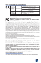
DECLARATIONS OF CONFORMITY EN 55022 (1998) 89/336/EEC modified by 92/31/EEC and 93/68/EEC EMC Directive 73/23/EEC modified by 93/68/EEC Low voltage Directive 1999/5/CE R&TTE Directive EN 301489-3 V1.4.1 EN 55024 (2001) RF Emissions control RF Emissions and immunity for radio equipment Immunity to Electromagnetic Disturbances EN 60950 (1992) and Amendments A1 to Product safety A11 (1997) EN300330-2 V1.1.
INTRODUCTION Thank you for choosing the Zebra P520i Plastic Card Printer. Zebra’s P520i card printers offer a low cost, high quality solution to those requiring computer-controlled printing and encoding of credit card style plastic cards, Card applications include personalized identification, access control, visitor, membership, badges and tags. This manual guides you to efficient start up and operation of your new Card Printer.
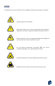
ICONS Throughout this manual, different icons highlight important information, as follows: Important general information. Mechanical hazard, such as one associated with moving parts, capable of resulting in equipment damage or personal injury. Electrical hazard, such as an exposed voltage point, capable of causing electrical shock and personal injury. An area where electrostatic discharge (ESD) can cause component damage. Use a grounding wrist band.
TABLE OF CONTENTS 1 2 GETTING STARTED • • • • • • • • • • 1 1•2 Indicators and control • • • • • • • • • • • • • • • • • • • • • • 1•3 Printer installation • • • • • • • • • • • • • • • • • • • • • • • • 3 4 OPERATION • • • • • • • • • • • • • • 3 4 5 2•1 2•2 2•3 2•4 Printer Features • • • • • • • • • • • • Loading Printing Ribbons • • • • • Loading Lamination Patch • • • • • Loading cards • • • • • • • • • • • • • A- Card Feeder • • • • • • • • • • • • • B- Card Cleaning Cartridge • • • • C- Card
APPENDIX A • • • • • • • • • • • • • • Introduction • • • • • • • • • • • • • • • • • • • • • • • • • • • • • • • A- Media Loading orientation • • • • • • • • • • • • • • • • B- Magnetic Encoder Cleaning • • • • • • • • • • • • • • • • APPENDIX B • • • • • • • • • • • • • • Introduction • • • • • • • • • • • • • • • • • • • • • • • • • • • • • • • A- Media Loading orientation • • • • • • • • • • • • • • • • B- Smart Card Contact Station Interface • • • • • • • • • APPENDIX C • • • • • • • • • • • • • • Av
x
1 GETTING STARTED 1 • 1 Unpacking your card printer Your P520i printer ships in a carton and protective anti-static bag. Keep all packaging material in case you need to move or re-ship the printer. While unpacking, inspect the carton to ensure that no damage occured during shipping. Please ensure that you have a clean and nearly dust free environment for proper operation and storage of the printer.
In addition to user documentation, make sure the following items are included with your P520i printer: CARD HOPPER CLEANING KIT POWER CABLE(5) CLEANING CARTRIDGE PRINTER DRIVER CD (Printer Documentation CD) Parallel CABLE (for “U” Interface Option only) If any items are missing, please contact your dealer. To reorder, please refer to Appendix C of this manual.
1 • 2 Indicators and Control Your P520i printer has an LCD Display, two LED’s and two Panel Buttons.
1 • 3 Printer Installation The following will guide you through the installation of your P520i printer. CAUTION: Limit AC power supplied to the P520i Printer to 110 - 230 V AC, 60 - 50 Hz for an associated 1,40A - 0,80A. Limit excess current draw to 16 amps or less, using an associated circuit breaker or other such device. Never operate the printer in a location where operator, computer, or printer can get wet. Personal injury could result.
4 • Attach and secure the interface cable to printer and computer. Note: In printers with two-connectors, use the USB or the Parallel/Ethernet, never both. 5 • Switch power on.
Ethernet Indicators The following shows the function of the switch and indicators found on P520i Printers that use Ethernet Computer Interfaces.
2 OPERATION 2 • 1 Printer Features The following shows the features found on your P520i Printer: Standard Features: Optional Features: 1 • Print Head Unlock Lever 2 • Print Head 3 • Card Thickness Control Lever 4 • Card Feeder 5 • LCD Display and two panel Buttons 6 • Card Cleaning Cartridge 7 • Laminator 8 • Laminator Unlock Lever 9 • Card Output Hopper 10 • Rejected Card Box 11 • Cleaning Roller A • Smart Card Contact Station B • Magnetic Encoder Station OPERATION 7
2 • 2 Loading Printing Ribbons The P520i Printer requires approved ribbons (see Appendix C). The Resin Thermal Transfer and Dye Sublimation ribbons and Lamination are specifically designed for your P520i Printer. For optimum performance and printer life (Print Head), always use approved ribbons. DO NOT TOUCH the print head or the electronic components on the print head carriage.
1 3 • Load ribbon onto the supply spindle “1” (under print head carriage) and empty core ( with tape attached) onto the take-up spindle “2”. Make sure the ribbon comes off the top of the supply spindle and feeds to the top of the take-up spindle. 2 4 • Push down on the Print Head Lock Lever until an audible “click” signals the locked-down position. 5 • Close Cover Please note that the ribbon automatically synchronises whenever the print head lock down occurs.
2 • 3 Loading Lamination Patch The P520i Printer requires approved patches (see Appendix C). Clear patches, hologram patches or Overlay varnishes are specifically designed for your P520i Printer. For optimum performance and printer life (Laminator), always use approved patches. 1 • Remove patch from packaging. 2 • With printer power ON and printer Ready status, open cover. 3 • Press down on the Laminator Unlock Lever to open the laminator bracket. The laminator bracket will pop open.
2 • 4 Loading Cards To help you load, print, and collect cards, the P520i has the following items: A - CARD FEEDER This items is used for loading cards. 1 • Open Card Feeder Cover by putting your fingers on both sides and rotating the cover in a clockwise direction to the open position. 2 • Install cards into Feeder* as shown. 3 • Close Card Feeder Cover. DO NOT bend cards or touch print surfaces as this can reduce print quality. The surface of the cards must remain clean and dust free.
B - INSTALL CARD CLEANING CARTRIDGE This items is used to clean the cards entering the printer. It must installed before using the printer. 1 • Remove Card Cleaning Cartridge from plastic bag and peel off protective wrapper from adhesive cleaning roller. 2 • Open printer cover and remove the yellow reminder tape from the location for the Cleaning Cartridge. 3 • Make sure the arrow on top of the assembly is facing towards the rear of the printer. Hook assembly into slot on printer and rotate down.
C - CARD THICKNESS CONTROL LEVER This items is operated by the user to prevent more than one card feeding into the printer at the same time and causing a jam. Open cover, and adjust lever to the correct position for the card thickness you are using. Repeat for different card thickness. (Factory setting is for 30 mil (0,762 mm) card thickness). See diagram below: Card thickness: A - 60mil (1.524mm) to 50mil (1.27mm) B - 40mil (1.016mm) C - 30mil (0.762mm) D - 20mil (0.508mm) E* - Less than 20mil (0.
2 • 5 Rejected Card Box The P520i Printer is equipped with a Rejected card Box. When an encoding can not be completed, the card is ejected into the Rejected Card Box. The P520i Printer counts the number of cards which go into the Reject Card Box. After 10 cards the printer stops, the Amber LED Flashes and a LCD Message is displayed indicating the need to empty the reject box.
3 • Swing the Rejected Card Box Door and press the top. An audible “click” signals the locked position. 4 • Press the Clear Button on the front panel to re-start the current printer job and to clear the rejected cards counter.
2 • 6 Feeding one card at a time A Manual Feed Slot is avalable on the side of the Card Feeder cover for feeding single cards. Cleaning Cards are fed manually through this slot. The Feeder must be empty for manual card feeding to work properly. For one-at-a-time printing, feed cards through slot on side of Feeder. Do not feed more than one card at a time.
2 • 7 Printing a Test Card With ribbon and cards loaded, your P520i printer is ready to print. To check the operation of the printer and the laminator you should print a test card. NOTE: Test cards are not laminated. 1 • When the printer displays READY, press the “Next” button (left) on your Control Panel to MENU PRINTER, then the “Select”button (right) to PRINTER INFO. 2 • Press twice the “Next” button to SELF TEST MENU and then “Select” to TEST PATTERN. 3 • A test card will print after a few seconds.
2 • 8 Printer Menu Information The printer is equipped with an LCD Display and two key buttons which gives access to printer menus. When the printer status shows READY, press the Menu button to enter the Menu Mode Menu Button “NEXT”(left) Clear Button “SELECT”(right) When you are in Menu Mode the top line display shows menu information and the second line of display clarifies the function of the two “NEXT” and “SELECT” key buttons relative to the current menu item.
Menu Tree: Printer station READY READY PRINTER MODULE MENU After 10 seconds of selection inactivity, READY returns automatically. PRINTER INFORMATION Model Number of Printer MODEL NAME Hold xxxx Firmware Version Installed FIRMWARE VER Hold V3.
Menu Tree: Laminating station READY READY After 10 seconds of selection inactivity, READY returns automatically. PRINTER MODULE MENU See Menu Mode Printer Group Model Number of Laminator LAMINATOR MENU LAMINATOR INFORMATION MODEL NAME Hold xxxx Firmware Version Installed FIRMWARE VER Vx.
Menu Tree: Test Cards and Cleaning READY READY After 10 seconds of selection inactivity, READY returns automatically.
22 OPERATION
3 PRINTING A SAMPLE CARD Printing with the P520i Printer requires the Windows Printer Driver, your card design/issuing software or printer command level programming through the printer interface. The P520i Card Printer can be used with any Windows 98 SE/ME, NT 4.0, 2000. or XP software application program, using the drivers provided with the printer. This section contains information on the printing of a dual-sided card in color (using the 5-Panel color ribbon YMCKK) and the Windows Printer Driver.
3 • 1 To install the P520i Printer Driver proceed as follows: IMPORTANT NOTE: Ensure that your PC printer port is set to ECP mode and also ensure that you have deleted any previous versions ot this printer driver. If you have any doubts please contact your IT department. ❐ Start your computer and then Windows. ❐ Insert your “Zebra Driver” CD into an available drive. ❐ Wait for the Driver Install Wizard to self-launch, and follow the instrutions.
3 • 2 Printing a sample card: You can either follow the steps below to print your first card or choose the sample card available during driver installation. ❐ Go to the Microsoft Word Software. ❐ If the printer was not selected as the default printer, go to the file menu and Select Printer and choose Zebra P520i Card Printer in the printer names list. Then Close the print dialog box. ❐ Come back to file menu and choose Page Setup. ❐ Select Paper Size tab and in Paper Size choose Card.
26 PRINTING A SAMPLE CARD
4 CLEANING PROTECT YOUR FACTORY WARRANTY! The recommended maintenance procedures must be performed to maintain your factory warranty. Other than the recommanded cleaning procedures described in this manual, allow only Zebra authorised technicians to service the P520i Printer. NEVER loosen, tighten, adjust, or bend, etc. a part or cable inside the printer. NEVER use a high pressure air compressor to remove particles in the printer.
4 • 1 Cleaning System Your P520i Printer includes a simple cleaning system using the Pre-Satured Cleaning Cards provided. The regular use of these cards will clean and maintain important parts of your printer that cannot be reached: including the Print Head, the Lamination station and Transport Rollers. CLEAN PRINTER WHEN TO CLEAN When the LCD screen reports messages. HOW TO CLEAN 1 • Leave power on. Open Cover and release Print Head Bracket. Remove ribbon. Close Print Head Bracket Close Cover.
4 • 2 Cleaning the Print Head A cleaning using the cleaning system with cards usually suffices. However, a separate Print head cleaning using swabs can remove more stubborn deposits when print anomalies persist. To avoid deposits, only use foam-tipped swabs. 1 • Switch power Off, open cover, raise Print Head and remove the Ribbon. 2 • Clean Print Head by moving alcohol-moistened swab tip side-to-side across Print Head elements. Only use moderate force. Make sure the elements are dry before switching on.
4 • 3 Cleaning the Laminator Rollers A cleaning using the Cleaning System with cards usually suffices, moreover your printer is equipped with two cleaning rollers situated before the card enter the Laminator. The upper roller has a coating that collects any loose particles on the surface of cards. However, a separate Laminator Station cleaning can remove more stubborn deposits. To avoid deposits, only use foam-tipped swabs. Never touch the rollers with fingers.
4 • 4 Card Cleaning Cartridge Your P520i Printer also has a Card Cleaning Cartridge. This item cleans the cards entering the printer. To ensure print quality, the cleaning roller requires periodic replacements. CLEAN PRINTER WHEN TO MAINTAIN When LCD screen reports message or at ribbon replacements. Run a printer cleaning first. (see 4.1 Cleaning System for more instructions).
3 • Remove Cleaning Roller from Cartridge and discard. 4 • Install new Cleaning Roller into Cartridge*. To avoid contamination, always hold the Cleaning Roller assembly by the ends. 5 • Carefully peel off wrapper from new Cleaning Roller while in Cartridge. 6 • Replace Cartridge into printer. Make sure the arrow on top of the assembly is facing towards the rear of the printer. Hook assembly into slot on printer and rotate down. Ensure the assembly locks in place.
5 TROUBLESHOOTING This section offers solutions to potential problems you may experience with your P520i printer. The table below lists the screen messages that will be displayed on the printer’s LCD, both during normal operation and to alert operator of any error conditions. There is also some additional information dealing with quality issues concerning printing onto cards.
A • Printing Station Status Messages (Continued) SCREEN MESSAGE MEANING ENCODING The printer is encoding the Magnetic Stripe. CLEAN PRINTER CLEANING FLIPPING CARD DOWNLOADING FW ACTION Carry out the cleaning procedure as detailed in section 4 of this manual. The printer is prompting for operator maintenance. The printer is performing an internal cleaning routine. A card-flip to the opposite side is occuring. Firmware is downloading to the printer.
C • Print Station Alert Messages SCREEN MESSAGE MEANING ACTION REMOVE RIBBON The ribbon has not been removed while the cleaning operation is in progress. Remove ribbon OUT OF RIBBON The printer ribbon has run out. Replace printer ribbon. Remove the jamed card.
D • Laminating Station Alert Messages MEANING SCREEN MESSAGE COVER OPEN HEAD OPEN OUT OF RIBBON OUT OF CARD MECHANICAL ERROR COMMAND ERROR NO ACCESS ROTATION ERROR RIBBON FAILURE TEMPERATURE ERR FLASH ERROR ACTION The cover is open. Close cover. The Laminator Head is raised. Latch down the Lamination Head. The Laminator has run out Load a new ribbon of ribbon. Check for a jamed card. There is no card in the Ensure the card is not out of Laminator. specification. An error occured while moving a card.
5 • 2 Print Quality Issues This section will help you resolve print quality problems. The print quality is dependent on several factors. The two most important factors that will increase your print quality are cleanliness and card stock. To diagnose and fix print quality problems, follow the troubleshooting procedure below: • Small spots appear on the printed card with a non-printed area or a different color. Possible Cause A • Contamination on the card surface.
• Printing shows very pale or inconsistent results. Possible Cause A • Ribbon have been stored improperly or is damaged. B • Cards may not meet specifications. C • Contrast and/or Intensity may be set to values which are too high. D • Dust or embedded contamination on elements of the Print Head. >> Solution A1 • Change ribbon and print again. B1 • Use a different supply of cards. C1 • Adjust Contrast and/or Intensity values in software.
• No printing on the card. Possible Cause A • Ribbon may not be installed in the printer. B • Cards may not meet specifications. C • Cable on Print Head may be disconnected. D • Print Head elements may be scratched or burnt. >> Solution A1 • Check for ribbon in the printer. B1 • Use a different supply of cards. C1 • Power off the printer and check the Print Head cable connections. D1 • Call Service for Print Head replacement information.
40 TROUBLESHOOTING
6 TECHNICAL SPECIFICATIONS General Color Printing Bar Code Fonts • High speed printing & laminating • Small footprint • Windows Drivers for 98SE, ME, NT 4.0, 2000, and XP • One year printer warranty • One year print head warranty` • Color dye sublimation or monochrome thermal transfer printing • 300 dpi (11.
CARD DIMENSIONS ISO STANDARD DIMENSIONS FOR PLAIN CARD ISO STANDARD DIMENSIONS FOR MAGNETIC STRIPE CARD CHIP POSITION FOR SMART CARD 0.357 in (9.07 mm) 0.720 in (18.3 mm) 0.757 in (19.23 mm) 1.121 in (28.46 mm) 0.403 in (10.25 mm) 0.782 in (19.87 mm) AFNOR Cards 42 TECHNICAL SPECIFICATION 0.403 in (10.25 mm) 0.782 in (19.
Ribbons • Monochrome: 1000/1500 cards/roll • Monochrome colors: back, red, blue, green, silver, gold, white. • K-resin + O: 500 cards/roll • K-dye + O: 500 cards/roll • YMC: 300 cards/roll • YMCK: 250/400 cards/roll • YMCK-K: 200 cards/roll • YMCKO: 200/330 cards/roll • YMCKOK: 170 cards/roll Patches • • • • • Clear Patch 1 or 0.6 mil Clear Patch for mag.
CENTRONIC CABLE INTERFACE The above drawing shows the required connections to use the printer centronic interface. Printer Pin Lign Name 1 -STROBE 2 DO 3 D1 4 D2 5 D3 6 D4 7 D5 8 D6 9 D7 10 -ACK 11 -BUSY 12 PE 13 SLCT 14 -AUTO FEED 32 -ERROR 31 -INIT 36 SLCT IN 19-30-33 GND Note: The printer pins number 15, 16, 18, 30, 34, 35 are not connected.
A APPENDIX Magnetic Card Stripe Encoder This section contains information on the additional operations of the P520i Printers with Magnetic Card Stripe Encoder. (See Chapter 2 for location.) INTRODUCTION Operation and maintenance requirements for the P520i Printer with the optional magnetic card stripe encoder. (See Chapter 2 for location.) The magnetic encoder can be set for either high or low coercivity.
A • MEDIA LOADING ORIENTATION The magnetic encoder is a factory installed item with the read/write head positioned below the card path, available with HICO encoding or LOCO encoding. When loading cards into the Card Cartridge, please ensure that the magnetic stripe is facing down and closest to the rear. Also available are Printer models with the Magnetic Read/Write head positioned above the card path, with HICO encoding or LOCO encoding.
B • MAGNETIC ENCODER CLEANING There exists two different processes to clean the Magnetic stripe Encoder. The first process consists of a standard cleaning of the printer. This cleans the most important parts of the printer; including the print Head, Transport Roller and Magnetic Stripe Encoder (refer to chapter 4 “Cleaning” for more instructions.) The second process consist of a cleaning of the Magnetic Encoder using the Menu Button from the LCD Display.
48 APPENDIX A
B APPENDIX Smart Card Contact Station This section contains information on the additional operations of the P520i Printers with Smart Card Contact Stations. (See Chapter 2 for location.) INTRODUCTION Your P520i may be equipped with an optional Smart Card contact station. Smart Cards can store fingerprints, voice recognition patterns, medical records and other such data.
A • MEDIA LOADING ORIENTATION Position the cards with the Smart Card Chip at the top of the card and towards the printer. B • SMART CARD CONTACT STATION INTERFACE When a command to the parallel printer interface sends a card to the Smart Card Contact Station, the printer connects the Smart Card Contact Station to the female DB-9 connector on the rear of the printer.
C APPENDIX Accessories & Supplies Please contact your Zebra authorised dealer to place an order for accessories and supplies. Use only Zebra-approved card, ribbon and patches media. Using non-approved card or ribbon media can void your warranty. Refer to the Accessories section for more information about Card and Ribbon Media available from Zebra Technologies Corp.
AVAILBLE MONOCHROME RIBBONS: Part Number Description 800015-101 800015-102 800015-103 800015-104 800015-106 800015-107 800015-109 800015-185 800015-301 Black Red Green Blue Gold Silver White Scratch-off Gray Black Cards/roll 1000 1000 1000 1000 1000 1000 1000 840 1500 Only 30 mil cards should be used when the card is to be laminated. Use 30 mil composite cards whenever possible to ensure compliance of the finished card to ISO flatness guidelines.
AVAILABLE PATCH RIBBONS: Part Number 800015-012 800015-013 800015-014 800015-031 800015-032 800015-033 800015-131 800015-135 Description Cards/roll Patch 1 mil Carrier-Based Rolls clear patch for cards w/mag. stripe 100 clear patch for smart cards 100 clear full coverage patches 100 clear full coverage alternating wWITH mag. stripe 100 (50 cards) Genuine Secure Hologram Image Patches 100 World Globe Hologram Image Patches 100 Zebra TrueSecure Varnish Overlays Clear 350 Zebra TrueSecure 0.
ACCESSORIES Accessories available for P520i printers appear below. Always refer to the part number when placing an order.
APPENDIX C 55
World Wide Sales and Support: Zebra Technologies Corporation Card Imaging Division 1001 Flynn Road Camarillo, CA 93021-8706.USA Phone: + 1(805) 579 1800 Fax.: + 1 (805) 579 1808 Toll Free in US: (800) 452-4056 e-mail: cards@zebracard.com Zebra Technologies Corporation Card Imaging Division, (Europe, Middle East, Africa) The Valley Centre, Gordon Road, High Wycombe Buckinghamshire HP13 6EQ, England Phone: + 44 (0) 870 241 1527 Fax.: + 44 (0) 870 241 0765 e-mail: eurosales@zebracard.