Zebra® ZE500™ User Guide P1051584-002 Rev.
© 2012 ZIH Corp. The copyrights in this manual and the software and/or firmware in the print engine described therein are owned by ZIH Corp. and Zebra’s licensors. Unauthorized reproduction of this manual or the software and/or firmware in the print engine may result in imprisonment of up to one year and fines of up to $10,000 (17 U.S.C.506). Copyright violators may be subject to civil liability.
Declaration of Conformity DECLARATION OF CONFORMITY ZEBRA TECHNOLOGIES CORPORATION Declares that the following Information Technology Equipment Zebra ZE500-4 and ZE500-6 complies with the following applicable directives and standards for the ITE: Heavy Industry environment Applicable Directives and Supporting Standards: 2004/108/EC EMC Directive, EN55022:2010 Class A, EN55024:2010EN61000-3-2:2006 + A2:2009, EN61000-3-3:2008, 2006/95/EC LVD Directive, EN60950-1:2006 (2nd Edition) +A11:2009 +A1:2010+A12:20
Compliance Information Compliance Information FCC Compliance Statement This device complies with Part 15 of the FCC rules. Operation is subject to the following two conditions: 1. This device may not cause harmful interference, and 2. This device must accept any interference received, including interference that may cause undesired operation. Note • This equipment has been tested and found to comply with the limits for a Class B digital device, pursuant to part 15 of the FCC Rules.
Contents About This Document . . . . . . . . . . . . . . . . . . . . . . . . . . . . . . . . . . . . . . . . . . . . . . . 9 Who Should Use This Document . . . . . . . . . . . . . . . . . . . . . . . . . . . . . . . . . . . . . . . . . . . 10 How This Document Is Organized . . . . . . . . . . . . . . . . . . . . . . . . . . . . . . . . . . . . . . . . . . 10 Contacts . . . . . . . . . . . . . . . . . . . . . . . . . . . . . . . . . . . . . . . . . . . . . . . . . . . . . . . . . . . . . . .
Contents Print Engine Installation . . . . . . . . . . . . . . . . . . . . . . . . . . . . . . . . . . . . . . . . . . . . . . . . . . Requirements . . . . . . . . . . . . . . . . . . . . . . . . . . . . . . . . . . . . . . . . . . . . . . . . . . . . . . Dimensions and Clearance Needs . . . . . . . . . . . . . . . . . . . . . . . . . . . . . . . . . . . . . . Install the Print Engine in an Applicator . . . . . . . . . . . . . . . . . . . . . . . . . . . . . . . . . . .
Contents Print Engine Diagnostics . . . . . . . . . . . . . . . . . . . . . . . . . . . . . . . . . . . . . . . . . . . . . . . . Power-On Self Test . . . . . . . . . . . . . . . . . . . . . . . . . . . . . . . . . . . . . . . . . . . . . . . . . CANCEL Self Test . . . . . . . . . . . . . . . . . . . . . . . . . . . . . . . . . . . . . . . . . . . . . . . . . . PAUSE Self Test . . . . . . . . . . . . . . . . . . . . . . . . . . . . . . . . . . . . . . . . . . . . . . . . . . . FEED Self Test . . . . . . .
Contents Notes • ___________________________________________________________________ __________________________________________________________________________ __________________________________________________________________________ __________________________________________________________________________ __________________________________________________________________________ __________________________________________________________________________ _______________________________________________
About This Document This section provides you with contact information, document structure and organization, and additional reference documents. Contents Who Should Use This Document . . . . . . . . . . . . . . . . . . . . . . . . . . . . . . . . . . . . . . . . . . . How This Document Is Organized . . . . . . . . . . . . . . . . . . . . . . . . . . . . . . . . . . . . . . . . . . Contacts . . . . . . . . . . . . . . . . . . . . . . . . . . . . . . . . . . . . . . . . . . . . . . . . . . . . . . . . . . .
About This Document Who Should Use This Document Who Should Use This Document This User Guide is intended for use by any person who needs to perform routine maintenance, upgrade, or troubleshoot problems with the print engine. How This Document Is Organized The User Guide is set up as follows: P1051584-002 Section Description Introduction on page 13 This section provides a high-level overview of the printer and its components.
About This Document Contacts Contacts Technical Support via the Internet is available 24 hours per day, 365 days per year. Web Site: www.zebra.com E-mail Back Technical Library: E-mail address: emb@zebra.com Subject line: Emaillist Self Service Knowledge Base: www.zebra.com/knowledgebase Online Case Registration: www.zebra.
About This Document Document Conventions Document Conventions Table 1 shows the way that certain information is conveyed in this document. Table 1 • Document Conventions Alternate Color If you are viewing this guide online, you can click the blue text used for cross-references or hyperlinks to jump directly to other sections in the guide or to web sites on the internet. LCD Display Examples Text from a print engine’s Liquid Crystal Display (LCD) appears in Arial font.
1 Introduction This section provides a high-level overview of the printer and its components. Contents Print Engine Orientation . . . . . . . . . . . . . . . . . . . . . . . . . . . . . . . . . . . . . . . . . . . . . . . . . . Print Engine Components . . . . . . . . . . . . . . . . . . . . . . . . . . . . . . . . . . . . . . . . . . . . . . . . Control Panel . . . . . . . . . . . . . . . . . . . . . . . . . . . . . . . . . . . . . . . . . . . . . . . . . . . . . . . . . . Control Panel Display. . . . . .
Introduction Print Engine Orientation Print Engine Orientation The ZE500 print engines are available in a right-hand configuration (the print mechanism is on the right) and a left-hand configuration (the print mechanism is on the left).
Introduction Print Engine Components Print Engine Components Figure 3 shows the components inside the media compartment of a right-hand print engine. A left-hand unit contains a mirror image of these components. Familiarize yourself with these components before continuing with the print engine setup procedure.
Introduction Control Panel Control Panel All controls and indicators for the print engine are located on the control panel (Figure 4). The power switch is located on top of the control panel. Figure 4 • Control Panel 1 10 1 2 3 POWER PAUSE 11 12 13 4 STATUS 5 6 7 8 DATA 9 14 The display shows the print engine’s operating status and allows the user to navigate the menu system. 2 POWER light On when the print engine is on. 3 PAUSE light On when the print engine is paused.
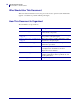
Introduction Control Panel Display Control Panel Display The control panel includes a display, where you can view the print engine’s status or change its operating parameters. In this section, you will learn how to navigate through the menu system and change values for menu items. After the print engine completes the power-up sequence, it moves to the Idle Display (Figure 5).
Introduction Control Panel Display Table 2 • Navigation (Continued) Perform an action + indicates that an action can be performed. Press PLUS (+) to perform the specified action. POWER PAUSE STATUS DATA Change Parameter Values - and + indicate that a value can be changed. POWER P1051584-002 PAUSE STATUS DATA Press PLUS (+) or MINUS (-) to scroll through the accepted values.
Introduction Control Panel Display Table 2 • Navigation (Continued) Exit Setup Mode POWER PAUSE STATUS DATA POWER PAUSE STATUS DATA 1. While in Setup Mode, press SETUP to exit the operating parameters. The LCD displays SAVE CHANGES. 2. To return to the parameters, plus the LEFT ARROW. OR Press PLUS (+) or MINUS (-) to scroll through the exit options. PERMANENT Stores values in the print engine even when power is turned off. TEMPORARY Saves the changes until power is turned off.
Introduction Control Panel Display Changing Password-Protected Parameters Certain parameters, including the communication parameters, are password-protected by factory default. Caution • Do not change password-protected parameters unless you have a complete understanding of the parameters’ functions. If the parameters are set incorrectly, the print engine may function unpredictably. The first time that you attempt to change a password-protected parameter, the print engine displays ENTER PASSWORD.
Introduction Control Panel Display Operating Parameters on the Control Panel Items in this menu are shown in the order in which they appear when you press the RIGHT ARROW. For more information about these settings, see Print Settings on page 73. Adjust the Print Darkness Set the darkness to the lowest setting that provides good print quality.
Introduction Control Panel Display Adjust the Tear-Off Position If necessary, adjust the position of the media over the tear-off bar after printing. See Tear-Off Position on page 74 for more information. Select the Print Mode Select a print mode that is compatible with your print engine options. See Print Mode on page 75 for more information. Select the Applicator Port Mode Select the appropriate action for the applicator port, as suggested by the applicator manufacturer.
Introduction Control Panel Display Select the Media Sensor Select the media sensor that is appropriate for the media that you are using. See Sensor Type on page 95 for more information. Select the Print Method Specify if ribbon is being used. Thermal Transfer media requires ribbon for printing while Direct Thermal media does not. To determine if you need to use ribbon, see When to Use Ribbon on page 41. See Print Method on page 76 for more information.
Introduction Control Panel Display Set Number of Labels Per Roll for Early Warning This value should correspond to the number of labels per roll of the media that you are using. See Early Warning for Media and Ribbon on page 82 for more information. * This parameter appears only if Early Warning for Media and Ribbon is enabled. Reset Media Counter for Early Warning Reset the media counter after you replace the media roll. • If you replaced the media, press PLUS (+) to select YES.
Introduction Control Panel Display Set Early Warning for Maintenance When this feature is enabled, the print engine provides warnings when the printhead needs to be cleaned. See Early Warning for Maintenance on page 82 for more information. Set Printhead Cleaning Interval* When Early Warning for Maintenance is enabled, set this value to the length of the media or ribbon roll that you are using. See Printhead Cleaning Interval on page 82 for more information.
Introduction Control Panel Display View the Non-Resettable Counter This parameter displays the total length of media that the printer has printed. See Non-Resettable Counter on page 83 for more information. View User-Controlled Counter 1 This parameter displays the total length of media that the printer has printed since this counter was last reset. See User-Controlled Counters on page 83 for more information.
Introduction Control Panel Display Print Bar Code List This option prints a label that lists the available bar codes in the print engine. Bar codes may be stored in RAM or Flash memory. See Print Information on page 84 for more information. Print Image List This option prints a label that lists the available images stored in the print engine’s RAM, Flash memory, or optional memory card. See Print Information on page 84 for more information.
Introduction Control Panel Display Print All Labels This option prints labels that list the available fonts, bar codes, images, formats, and the current print engine and network configurations. See Print Information on page 84 for more information. Initialize Flash Memory This option erases all previously stored information from Flash memory. 1. If prompted for a password, enter the printer password. For instructions, see Changing Password-Protected Parameters on page 20.
Introduction Control Panel Display Set Parallel Communications Select the communications port that matches the one being used by the host computer. See Parallel Communications on page 96 for more information. Set Serial Communications Select the communications port that matches the one being used by the host computer. See Parallel Communications on page 96 for more information. Set the Baud Rate Select the baud value that matches the one being used by the host computer.
Introduction Control Panel Display Set the Host Handshake Protocol Value Select the handshake protocol that matches the one being used by the host computer. See Host Handshake on page 98 for more information. Set the Zebra Protocol Value Protocol is a type of error checking system. Depending on the selection, an indicator may be sent from the print engine to the host computer signifying that data has been received. Select the protocol that is requested by the host computer.
Introduction Control Panel Display Set the Format Command Prefix Value Set the format command prefix character to match what is used in your label formats. See Command Character on page 94 for more information. Set the Delimiter Character Value Set the delimiter character to match what is used in your label formats. See Delimiter Character on page 94 for more information. Set the ZPL Mode Select the ZPL mode that matches what is used in your label formats. See ZPL Mode on page 94 for more information.
Introduction Control Panel Display Set the Head-Close Action Set the action for the printer to take when you close the printhead. See Head-Close Action on page 85 for more information. Set the Backfeed Sequence This parameter sets when label backfeed occurs after a label is removed in some print modes. It has no effect in Rewind mode. This setting is superseded by ~JS when received as part of a label format. See Backfeed Sequence on page 79 for more information.
Introduction Control Panel Display Set Applicator Error Signal When Print Engine Pauses When this option is enabled and the print engine is paused, the print engine sets the applicator error state. See Error on Pause on page 80 for more information. Set the Ribbon Low Mode The Ribbon Low feature determines if the print engine will generate a warning when the amount of ribbon left on the roll gets low. See Ribbon Low Mode on page 81 for more information.
Introduction Control Panel Display View Sensor Settings The following parameters are automatically set during the calibration procedure and should be changed only by a qualified service technician. Select Format Conversion Scaling Factor Selects the bitmap scaling factor. The first number is the original dots per inch (dpi) value; the second, the dpi to which you would like to scale. See Format Conversion on page 87 for more information.
Introduction Control Panel Display Set the Real-Time Clock (RTC) Date This parameter allows you to set the date to display in the Idle Display. See RTC Date on page 88 for more information. Set the Real-Time Clock (RTC) Time This parameter allows you to set the date to display in the Idle Display. See RTC Time on page 88 for more information. Run the Specified ZBI Program* • To run the ZBI program selected by the previous menu item, press PLUS (+).
Introduction Control Panel Display View the Active Print Server* This menu item displays which print server is being used. This tells which device’s settings such as IP protocol and IP address are being displayed under those menu items. * This menu item, which cannot be modified from the control panel, appears only if a wired or wireless print server is installed in your printer. Set the IP Resolution Method* This parameter tells if the user (permanent) or the server (dynamic) selects the IP address.
Introduction Control Panel Display Set the Default Gateway* View and, if necessary, change the default gateway. Changes are saved only if IP PROTOCOL is set to PERMANENT. To allow any saved changes to take effect, use RESET NETWORK on page 37 to reset the print server. See Default Gateway on page 91 for more information. * This menu item appears only if a wired or wireless print server is installed in your printer.
Introduction Control Panel Display Specify the Password Level This option resets the wired or wireless print server. You must reset the print server to allow any changes to the network settings to take effect. See Password Level on page 88 for more information. * This menu item appears only if a wired or wireless print server is installed in your printer. Select the Display Language If necessary, change the language that the printer displays. See Language on page 93 for more information.
Printer Setup and Operation Types of Media Types of Media Important • Zebra strongly recommends the use of Zebra-brand supplies for continuous high-quality printing. A wide range of paper, polypropylene, polyester, and vinyl stock has been specifically engineered to enhance the printing capabilities of the print engine and to prevent premature printhead wear. To purchase supplies, go to http://www.zebra.com/howtobuy.
Printer Setup and Operation Types of Media Table 3 • Roll and Fanfold Media (Continued) Media Type How It Looks Description Non-Continuous Fanfold Media Fanfold media is folded in a zigzag pattern. Fanfold media can have the same label separations as non-continuous roll media. The separations would fall on or near the folds. Note • The use of fanfold media is not recommended. Continuous Roll Media Roll media is wound on a 3-in. (76-mm) core.
Printer Setup and Operation Ribbon Overview Ribbon Overview Ribbon is a thin film that is coated on one side with wax, resin, or wax resin, which is transferred to the media during the thermal transfer process. The media determines whether you need to use ribbon and how wide the ribbon must be. When ribbon is used, it must be as wide as or wider than the media being used. If the ribbon is narrower than the media, areas of the printhead are unprotected and subject to premature wear.
Printer Setup and Operation Ribbon Overview Adhesive Test If you have labels available, perform the adhesive test to determine which side of a ribbon is coated. This method works well for ribbon that is already installed. To perform an adhesive test, complete these steps: 1. Peel a label from its liner. 2. Press a corner of the sticky side of the label to the outer surface of the roll of ribbon. 3. Peel the label off of the ribbon. 4. Observe the results.
2 Printer Setup and Operation This section assists the technician with initial setup and operation of the print engine. Contents Handling the Print Engine . . . . . . . . . . . . . . . . . . . . . . . . . . . . . . . . . . . . . . . . . . . . . . . . Unpack and Inspect the Print Engine. . . . . . . . . . . . . . . . . . . . . . . . . . . . . . . . . . . . . . Remove Additional Shipping Materials . . . . . . . . . . . . . . . . . . . . . . . . . . . . . . . . . . . . To Store the Print Engine . . . . . . .
Printer Setup and Operation Handling the Print Engine Handling the Print Engine This section describes how to handle your print engine. Unpack and Inspect the Print Engine Important • Zebra Technologies is not responsible for any damage incurred during the shipment of the equipment and will not repair this damage under warranty. When you receive the print engine, do the following: 1. Immediately unpack the print engine. 2. Check all exterior surfaces for damage. 3.
Printer Setup and Operation Handling the Print Engine 2. Remove the metal spacer that ships next to the printhead-release latch. (Right-hand unit shown.) a. Cut the cable tie (1) that secured the printhead-release latch during shipping. 1 b. 8/23/12 Rotate the printhead-release latch to expose the metal spacer.
Printer Setup and Operation Handling the Print Engine c. Remove the metal spacer. d. Rotate the printhead-release latch to the closed position. 3. Cut and remove other cable ties that were used in the media compartment (if any).
Printer Setup and Operation Handling the Print Engine To Store the Print Engine If you are not placing the print engine into immediate operation, repackage it using the original packing materials. You may store the print engine under the following conditions: • Temperature: –40°F to 140°F (–40° to 60°C) • Relative humidity: 5% to 85% non-condensing To Ship the Print Engine Save all packing materials in case you need to ship the print engine in the future. To ship the print engine, do the following: 1.
Printer Setup and Operation Print Engine Installation Print Engine Installation This section provides basic information for mounting the print engine into an applicator. The illustrations in this section show the print engine from different angles and include dimensions and clearance needs. Requirements Stability When the print engine is mounted, the complete assembly must be physically stable. When the print engine is loaded with ribbon and media, the equipment must not become physically unstable.
Printer Setup and Operation Print Engine Installation Dimensions and Clearance Needs This section shows measurements relevant when installing the ZE500 print engine in an applicator. Front View (Right-Hand Print Engine Shown) 5 mounting screws - 0.218 in. (5.5 mm) through - counterbore 0.350 in. x 0.197 in. (8.9 x 5 mm) deep - socket head cap screw (M5) 0.669 in. (17 mm) 18° 0.532 in (13.50 mm) 0.721 in (18.31 mm) 8/23/12 0.335 in. (8.
Printer Setup and Operation Print Engine Installation Rear View 9.648 in. (245 ± 0.1 mm) 0.445 in. (11.
Printer Setup and Operation Print Engine Installation Top View 16.62 in. (422.
Printer Setup and Operation Print Engine Installation Side View—ZE500-4 Print Engine First print element 0.613 in. (15.6 mm) 12.13 in (308.2 mm) Mainframe 52 0.52 in. (13.2 mm) Ribbon and media edge 1.454 in. (37 mm) 15.89 in. (403.7 mm) 12.73 in. (323.2 mm) 7.34 in. (186.5 mm) 14.95 in. (379.73 mm) 19.87 in. (504.
Printer Setup and Operation Print Engine Installation Side View—ZE500-6 Print Engine 0.613 in. (15.6 mm) Mainframe First print element 0.52 in. (13.
Printer Setup and Operation Print Engine Installation Install the Print Engine in an Applicator This section provides the basic instructions for installing the print engine into an applicator. Caution • If the print engine is installed improperly, it could fall out of the applicator and cause injury. The center mounting bolt and four mounting screws must be installed and secured. See Figure 7 for the location of the bolt and screws.
Printer Setup and Operation Select a Data Communication Interface Select a Data Communication Interface You may connect your print engine to a computer using one or more of the available connections. The standard connections are shown in Figure 8. A ZebraNet wired or wireless print server option or a parallel port may also be present on your print engine.
Printer Setup and Operation Select a Data Communication Interface Caution • Ensure that the print engine power is off (O) before connecting data communications cables. Connecting a data communications cable while the power is on (I) may damage the print engine. Table 4 • Data Communication Interfaces Interface Standard or Option RS-232 Serial Standard Description Limitations and Requirements • Maximum cable length of 50 ft (15.24 m).
Printer Setup and Operation Select a Data Communication Interface Table 4 • Data Communication Interfaces (Continued) Interface Standard or Option Applicator Option Description Limitations and Requirements The applicator interface is used to control the print engine from an external device (usually a label applicator).
Printer Setup and Operation Select a Data Communication Interface Table 4 • Data Communication Interfaces (Continued) Interface Standard or Option Wireless print server Option Description Limitations and Requirements • Can print to the print engine from any computer on your Wireless Local Area Network (WLAN). • Can communicate with the printer through the print engine’s web pages. • The print engine must be configured to use your WLAN.
Printer Setup and Operation Connect the Print Engine to a Power Source Connect the Print Engine to a Power Source The AC power cord must have a three-prong female connector on one end that plugs into the mating AC power connector at the rear of the print engine. If a power cable was not included with your print engine, refer to Power Cord Specifications on page 60.
Printer Setup and Operation Connect the Print Engine to a Power Source 3. Turn on (I) the print engine. The print engine boots up and performs a self-test. Power Cord Specifications Caution • For personnel and equipment safety, always use an approved three-conductor power cord specific to the region or country intended for installation. This cord must use an IEC 320 female connector and the appropriate region-specific, three-conductor grounded plug configuration.
Printer Setup and Operation Connect the Print Engine to a Power Source Figure 9 • Power Cord Specifications 2 3 1 4 1 2 3 4 AC power plug for your country—This should bear the certification mark of at least one of the known international safety organizations (Figure 10). 3-conductor HAR cable or other cable approved for your country. IEC 320 connector—This should bear the certification mark of at least one of the known international safety organizations (Figure 10). Length ≤ 9.8 ft. (3 m).
Printer Setup and Operation Load Ribbon and Media Load Ribbon and Media Use the instructions in this section to load ribbon (if used) and media in a ZE500™ print engine. Ribbon is used with thermal transfer labels. For direct thermal labels, do not load ribbon in the print engine. To determine if ribbon must be used with a particular media, see When to Use Ribbon on page 41.
Printer Setup and Operation Load Ribbon and Media 2. Position the ribbon roll with the loose end unrolling in the direction shown. LH RH 3. Place the roll of ribbon on the ribbon supply spindle. Push the roll back as far as it will go. LH RH 4. Place an empty ribbon core on the ribbon take-up spindle. Push the core back as far as it will go.
Printer Setup and Operation Load Ribbon and Media 5. Caution • The printhead may be hot and could cause severe burns. Allow the printhead to cool. Thread the ribbon under the lower ribbon guide roller (1), under the printhead assembly (2), and then over the upper ribbon guide roller (3). 3 3 1 1 2 2 LH RH 6. Wind the ribbon around the core on the ribbon take-up spindle.
Printer Setup and Operation Load Ribbon and Media Loading Media 7. Load media on the media supply reel of the applicator (refer to the applicator’s documentation for more information). 8. Press the release button on the pinch roller assembly. Allow the assembly to pivot upward. LH RH 9. Slide the media guide all the way out.
Printer Setup and Operation Load Ribbon and Media 10. Thread the media under the upper guide post (1), below the pinch roller assembly (2), and under the printhead assembly (3). 2 1 1 2 3 3 LH RH 11. Extend approximately 30 in. (75 cm) of media past the peel bar. Remove and discard the labels from the liner on this exposed media.
Printer Setup and Operation Load Ribbon and Media 12. Slide in the media guide until it just touches the edge of the media. LH RH 13. Press down on the pinch roller assembly until it locks closed. LH RH 14. Rotate the printhead-release latch to the closed position.
Printer Setup and Operation Load Ribbon and Media 15. Raise the peel roller latch so that the peel roller assembly pivots downward. LH RH 16. Thread the liner around the peel bar, under the platen roller, and through the peel roller assembly. Important • If the applicator has an air tube, route the liner between the air tube and the peel bar. Do not thread the liner over the air tube.
Printer Setup and Operation Load Ribbon and Media 17. Rotate the peel roller assembly up until it locks into the closed position. LH RH 18. Thread the liner around the take-up spindle of the applicator (refer to the applicator’s documentation for more information). 19. Close the media door. 20. If desired, perform the CANCEL Self Test on page 131 to verify that your printer is able to print.
Printer Setup and Operation Load Ribbon and Media Notes • ___________________________________________________________________ __________________________________________________________________________ __________________________________________________________________________ __________________________________________________________________________ __________________________________________________________________________ __________________________________________________________________________ _____
3 Printer Configuration and Adjustment This section assists you with configuration of and adjustments to the print engine. Contents Changing Printer Settings . . . . . . . . . . . . . . . . . . . . . . . . . . . . . . . . . . . . . . . . . . . . . . . . 72 Print Settings . . . . . . . . . . . . . . . . . . . . . . . . . . . . . . . . . . . . . . . . . . . . . . . . . . . . . . . . 73 Maintenance and Diagnostic Tools . . . . . . . . . . . . . . . . . . . . . . . . . . . . . . . . . . . . . . .
Printer Configuration and Adjustment Changing Printer Settings Changing Printer Settings This section presents the printer settings that you can change and identifies the tools for changing them. These tools include the following: • ZPL and Set/Get/Do (SGD) commands (See the Zebra® Programming Guide for more information.) • The printer’s control panel display (See Control Panel Display on page 17 for more information.
Printer Configuration and Adjustment Changing Printer Settings Print Settings Table 5 • Print Settings Print Darkness Set the darkness to the lowest setting that provides good print quality. If you set the darkness too high, the label image may print unclearly, bar codes may not scan correctly, the ribbon may burn through, or the printhead may wear prematurely. If desired, use the FEED Self Test on page 133 to determine the best darkness setting. Accepted values: 0.0 – 30.
Printer Configuration and Adjustment Changing Printer Settings Table 5 • Print Settings (Continued) Backfeed Speed Backfeed refers to the backward motion of the media from the tear-off or peel-off position to the print position. This motion occurs so that more of the lead edge of each label can be used for printing. Reducing backfeed speed can mitigate some issues. In general, reducing the backfeed speed may improve print quality at the start of the label. This speed defaults to 2 ips.
Printer Configuration and Adjustment Changing Printer Settings Table 5 • Print Settings (Continued) Print Mode Select a print mode that is compatible with your print engine options. Accepted values: • • • • APPLICATOR—The print engine prints a label when it receives a signal from the applicator. TEAR OFF—The print engine prints label formats as it receives them. The print engine operator can tear off the printed labels any time after they print.
Printer Configuration and Adjustment Changing Printer Settings Table 5 • Print Settings (Continued) Start Print Signal This parameter determines how the print engine reacts to the Start Print Signal input on pin 3 of the applicator interface connector at the rear of the print engine. Important • The Start Print Signal is determined by the applicator manufacturer. The print engine must use the correct setting for it to work properly.
Printer Configuration and Adjustment Changing Printer Settings Table 5 • Print Settings (Continued) Print Width Specify the width of the labels being used. Note • Setting the width too narrow can result in portions of a label format not being printed on the media. Setting the width too wide wastes formatting memory and can cause the printer to print off of the label and onto the platen roller.
Printer Configuration and Adjustment Changing Printer Settings Table 5 • Print Settings (Continued) Maximum Label Length Set the maximum label length to a value that is at least 1.0 in. (25.4 mm) greater than the actual label length plus the interlabel gap. If you set the value to one that is smaller than the label length, the print engine assumes that continuous media is loaded, and the print engine cannot calibrate. For example, if the label length is 6.
Printer Configuration and Adjustment Changing Printer Settings Table 5 • Print Settings (Continued) Ribbon Tension Select the ribbon tension setting that is appropriate for the width or type of media being printed. HIGH can be used for most media. The correct setting is determined by a combination of the ribbon width and the ribbon length (Table 6). If necessary, use a lower value for narrow media or for glossy media.
Printer Configuration and Adjustment Changing Printer Settings Table 5 • Print Settings (Continued) Label Top Position This parameter adjusts the print position vertically on the label. Positive numbers adjust the label top position farther down the label (away from the printhead) by the specified number of dots. Negative numbers adjust the position up the label (toward the printhead).
Printer Configuration and Adjustment Changing Printer Settings Table 5 • Print Settings (Continued) Ribbon Low Mode The Ribbon Low feature determines if the print engine will generate a warning when the amount of ribbon left on the roll gets low. When the Ribbon Low feature is off, the output signal (Pin 9) does not function, the LOW RIBBON warning is not displayed, and the print engine continues to print until it runs out of ribbon.
Printer Configuration and Adjustment Changing Printer Settings Maintenance and Diagnostic Tools Table 7 • Maintenance and Diagnostic Tools Early Warning for Media and Ribbon When this feature is enabled, the print engine provides warnings when the media or ribbon is reaching near the end of the roll.
Printer Configuration and Adjustment Changing Printer Settings Table 7 • Maintenance and Diagnostic Tools (Continued) Non-Resettable Counter The non-resettable counter gives the total length of media that the printer has printed. You can use firmware commands to change the unit of measure for this counter.
Printer Configuration and Adjustment Changing Printer Settings Table 7 • Maintenance and Diagnostic Tools (Continued) Print Information Print the specified information on one or more labels. • FONTS—Prints the available fonts in the print engine, including standard print engine fonts plus any optional fonts. Fonts may be stored in RAM or Flash memory. • BAR CODES—Prints the available bar codes in the print engine. Bar codes may be stored in RAM or Flash memory.
Printer Configuration and Adjustment Changing Printer Settings Table 7 • Maintenance and Diagnostic Tools (Continued) Power-Up Action Set the Power-Up Action Set the action for the printer to take during the power-up sequence. • CALIBRATE adjusts sensor levels and thresholds, determines the label length, and feeds the media to the next web. • FEED—feeds the labels to the first registration point. • LENGTH determines the label length using current sensor values, and feeds the media to the next web.
Printer Configuration and Adjustment Changing Printer Settings Table 7 • Maintenance and Diagnostic Tools (Continued) Load Defaults Load Printer or Print Server Defaults • FACTORY—Restores all printer settings other than the network settings back to the factory defaults. Use care when loading defaults because you will need to reload all settings that you changed manually. • NETWORK—Reinitializes the printer’s wired or wireless print server.
Printer Configuration and Adjustment Changing Printer Settings Table 7 • Maintenance and Diagnostic Tools (Continued) Media and Ribbon Sensor Calibration Calibrate the printer to adjust the sensitivity of the media and ribbon sensors. For complete instructions on how to perform a calibration procedure, see Calibrate the Ribbon and Media Sensors on page 99.
Printer Configuration and Adjustment Changing Printer Settings Table 7 • Maintenance and Diagnostic Tools (Continued) Idle Display Select the information shown on the printer’s display when the printer is idle.
Printer Configuration and Adjustment Changing Printer Settings Network Settings Table 8 • Network Settings Primary Network Select the Primary Network Device This parameter determines which device should be considered primary in the active device selection. Accepted values: • • WIRED WIRELESS Related ZPL command(s): ^NC SGD command used: ip.
Printer Configuration and Adjustment Changing Printer Settings Table 8 • Network Settings (Continued) IP Protocol Set the IP Resolution Method This parameter tells if the user (permanent) or the server (dynamic) selects the IP address. If a dynamic option is chosen, this parameter tells the method(s) by which the wired or wireless print server receives the IP address from the server.
Printer Configuration and Adjustment Changing Printer Settings Table 8 • Network Settings (Continued) Subnet Mask View or Set the Subnet Mask View and, if necessary, change the subnet mask. This menu item appears only if a wired or wireless print server is installed on your printer. To save changes to this setting, set IP PROTOCOL to PERMANENT, and then reset the print server (see Reset Network on page 92).
Printer Configuration and Adjustment Changing Printer Settings Table 8 • Network Settings (Continued) ESSID View the ESSID Value The Extended Service Set Identification (ESSID) is an identifier for your wireless network. This setting, which cannot be modified from the control panel, gives the ESSID for the current wireless configuration. Accepted values: 32-character alphanumeric string (default 125) Related ZPL command(s): none SGD command used: wlan.
Printer Configuration and Adjustment Changing Printer Settings Language Settings Table 9 • Language Settings Language If necessary, change the language that the printer displays. This change affects the words shown on the following: • status and error messages • the printer parameters • the printer configuration label, the network configuration label, and other labels that you can select to print through the user menus (This does not apply to Japanese, Korean, Simplified Chinese, or Traditional Chinese.
Printer Configuration and Adjustment Changing Printer Settings Table 9 • Language Settings (Continued) Command Character Set the Format Command Prefix Value The format command prefix is a two-digit hex value used as a parameter place marker in ZPL/ZPL II format instructions. The print engine looks for this hex character to indicate the start of a ZPL/ZPL II format instruction. Set the format command prefix character to match what is used in your label formats.
Printer Configuration and Adjustment Changing Printer Settings Sensor Settings Table 10 • Sensor Settings Sensor Type Select the Media Sensor Select the media sensor that is appropriate for the media that you are using.
Printer Configuration and Adjustment Changing Printer Settings Port Settings Table 11 • Port Settings Parallel Communications Set Parallel Communications Select the communications port that matches the one being used by the host computer. Accepted values: • • BIDIRECTIONAL UNIDIRECTIONAL Related ZPL command(s): none SGD command used: none Control panel menu item: PARRALEL COMM.
Printer Configuration and Adjustment Changing Printer Settings Table 11 • Port Settings (Continued) Baud Rate Set the Baud Rate Select the baud value that matches the one being used by the host computer. Accepted values: • • • • • • • • • • • • 115200 57600 38400 28800 19200 14400 9600 4800 2400 1200 600 300 Related ZPL command(s): ^SC SGD command used: comm.
Printer Configuration and Adjustment Changing Printer Settings Table 11 • Port Settings (Continued) Host Handshake Set the Host Handshake Protocol Value Select the handshake protocol that matches the one being used by the host computer.
Printer Configuration and Adjustment Calibrate the Ribbon and Media Sensors Calibrate the Ribbon and Media Sensors Use the procedure in this section to calibrate the printer, which adjusts the sensitivity of the media and ribbon sensors. • For issues that may be resolved by sensor calibration, see Printing Issues on page 118. • For a summary of the options for initiating calibration, see Media and Ribbon Sensor Calibration on page 87. Important • Follow the calibration procedure exactly as presented.
Printer Configuration and Adjustment Calibrate the Ribbon and Media Sensors 2. Caution • The printhead may be hot and could cause severe burns. Allow the printhead to cool. Rotate the printhead-release latch to the open position. LH RH 3. Extend approximately 8 in. (203 mm) of media past the peel bar. Remove and discard the labels from the liner on this exposed media.
Printer Configuration and Adjustment Calibrate the Ribbon and Media Sensors 4. Pull the media back into the print engine so that only the liner is between the media sensors. 5. Press PLUS (+) to continue. The control panel displays: REMOVE RIBBON 6. Remove the ribbon (if used). 7. Rotate the printhead-release latch to the closed position, and close the media door. LH RH 8. Press PAUSE to begin the media calibration process.
Printer Configuration and Adjustment Calibrate the Ribbon and Media Sensors 11. Rotate the printhead-release latch to the closed position. LH RH 12. Close the media door. 13. Press PAUSE to enable printing.
Printer Configuration and Adjustment Remove Used Ribbon Remove Used Ribbon Remove used ribbon from the ribbon take-up spindle each time you change the roll of ribbon. To remove used ribbon, complete these steps: 1. Has the ribbon run out? If the ribbon... Then Ran out Continue with step 2. Did not run out a. Cut or break the ribbon before the ribbon take-up spindle. LH RH b. Continue with step 2. 2. Slide the core with the used ribbon off of the ribbon take-up spindle. LH RH 3.
Printer Configuration and Adjustment Adjust the Sensors Adjust the Sensors This section describes how to adjust the sensors. Transmissive Media Sensor The transmissive media sensor finds “start of label” indicators, such as notches or holes in the media or interlabel gaps. This sensor consists of a light source (positioned below the media) and a light sensor (positioned above the media). To position the sensor, complete these steps: 1. Refer to Figure 11.
Printer Configuration and Adjustment Adjust the Sensors Reflective Media Sensor Some types of media have black marks printed on the underside of the media liner, which act as “start of label” indicators. The reflective media sensor senses these black marks. The position of this sensor is not adjustable. If you use this type of media, refer to Media Specifications on page 144 for information about black mark requirements.
Printer Configuration and Adjustment Toggle Positioning Toggle Positioning Proper toggle positioning is important for proper print quality. Caution • Observe proper electrostatic safety precautions when handling any static-sensitive components such as circuit boards and printheads. To adjust the toggles, complete these steps: 1. Print some labels at 2 in. (51 mm) per second by running the PAUSE Self Test (see PAUSE Self Test on page 132). 2.
Printer Configuration and Adjustment Toggle Positioning 6. Print additional labels at 2 in. (51 mm) per second by again running the PAUSE Self Test. (Press and hold PAUSE while turning on (I) the printer.) 7. Do both sides of the label print at the same level of gray? If… Then… Yes The toggles are positioned correctly. Increase the darkness setting to the optimum level for the media being used. No a. Readjust the position of the toggle or toggles toward the side that printed lighter. b.
Printer Configuration and Adjustment Printhead Pressure Adjustment Printhead Pressure Adjustment Before adjusting the printhead pressure, check that the toggles are positioned correctly. See Toggle Positioning on page 106. Printhead life and drive system life (belts and bearings) can be maximized by using the lowest pressure that produces the desired print quality without allowing the ribbon or media to slip.
Printer Configuration and Adjustment Printhead Pressure Adjustment 4. Caution • The printhead may be hot and could cause severe burns. Allow the printhead to cool. As a starting point for adjustment, set the position of the adjusting nut (1) and the locking nut (2) so that when the locking nut is tightened, it is approximately 5/16 in. (8 mm) from the yoke (3). 3 5/16 in. (8 mm) 2 1 5. Move the adjusting nut until the print quality is acceptable.
Printer Configuration and Adjustment Printhead Pressure Adjustment Notes • ___________________________________________________________________ __________________________________________________________________________ __________________________________________________________________________ __________________________________________________________________________ __________________________________________________________________________ ______________________________________________________________
4 Routine Maintenance This section provides routine cleaning and maintenance procedures. Contents Cleaning Schedule . . . . . . . . . . . . . . . . . . . . . . . . . . . . . . . . . . . . . . . . . . . . . . . . . . . . . Clean the Exterior . . . . . . . . . . . . . . . . . . . . . . . . . . . . . . . . . . . . . . . . . . . . . . . . . . . . . Clean the Media Compartment . . . . . . . . . . . . . . . . . . . . . . . . . . . . . . . . . . . . . . . . . . . Clean the Printhead and Rollers . . . . . . . . .
Routine Maintenance Cleaning Schedule Cleaning Schedule Cleaning your print engine regularly maintains print quality and may extend the life of the print engine. The recommended cleaning schedule is shown in Table 12. See the following pages for specific procedures. Caution • Use only the cleaning agents indicated. Zebra is not responsible for damage caused by any other fluids being used on this print engine.
Routine Maintenance Clean the Media Compartment Clean the Media Compartment Remove any accumulated dirt and lint from the interior of the print engine using a soft bristle brush and/or vacuum cleaner. This area should be inspected every time a new ribbon is loaded. Clean the Printhead and Rollers Clean the printhead, platen roller, pinch roller, and peel roller according to the schedule in Table 12 on page 112.
Routine Maintenance Clean the Printhead and Rollers 4. Using Preventative Maintenance kit (part number 47362) or a solution of 90% isopropyl alcohol and 10% deionized water on a cotton swab, wipe the print elements from end to end. Allow the solvent to evaporate. 1 2 3 1 2 3 Printhead elements (gray strip) Cotton swab Platen Roller 5. Use a lint-free cloth moistened with alcohol to clean the platen roller, pinch roller, and peel roller. Rotate the rollers while cleaning. 6.
Routine Maintenance Replacing Print Engine Components Replacing Print Engine Components Some print engine components, such as the printhead and platen roller, may wear out over time and can be replaced easily. Regular cleaning may extend the life of some of these components. See Cleaning Schedule on page 112 for the recommended cleaning intervals.
Routine Maintenance Lubrication Notes • ___________________________________________________________________ __________________________________________________________________________ __________________________________________________________________________ __________________________________________________________________________ __________________________________________________________________________ __________________________________________________________________________ ______________________
5 Troubleshooting This section provides information about errors that you might need to troubleshoot. Assorted diagnostic tests are included. Contents Printing Issues . . . . . . . . . . . . . . . . . . . . . . . . . . . . . . . . . . . . . . . . . . . . . . . . . . . . . . . . Ribbon Problems . . . . . . . . . . . . . . . . . . . . . . . . . . . . . . . . . . . . . . . . . . . . . . . . . . . . . . Error Messages . . . . . . . . . . . . . . . . . . . . . . . . . . . . . . . . . . . . . . . . . . . . . .
Troubleshooting Printing Issues Printing Issues Table 13 identifies possible issues with printing or print quality, the possible causes, and the recommended solutions. Table 13 • Printing Issues Issue Possible Cause Recommended Solution General print quality issues The print engine is set at an incorrect print speed. For optimal print quality, set the print speed to the lowest possible setting for your application via control panel, the driver, or the software.
Troubleshooting Printing Issues Table 13 • Printing Issues (Continued) Issue Possible Cause Recommended Solution Long tracks of missing print on several labels Print element damaged. Call a service technician. Wrinkled ribbon. See wrinkled ribbon causes and solutions in Ribbon Problems on page 121. Fine, angular gray lines on blank labels Wrinkled ribbon. See wrinkled ribbon causes and solutions in Ribbon Problems on page 121.
Troubleshooting Printing Issues Table 13 • Printing Issues (Continued) Issue Possible Cause Vertical image or label drift The print engine is using Set the print engine for the correct media type non-continuous labels but is (gap/notch, continuous, or mark—see Media configured in continuous mode. Type on page 76) and calibrate the printer, if necessary (see Calibrate the Ribbon and Media Sensors on page 99). The bar code printed on a label does not scan. The media sensor is calibrated improperly.
Troubleshooting Ribbon Problems Ribbon Problems Table 14 identifies problems that may occur with ribbon, the possible causes, and the recommended solutions. Table 14 • Ribbon Problems Problem Possible Cause Recommended Solution Broken or melted ribbon Darkness setting too high. 1. The ribbon is coated on the wrong side and cannot be used in this print engine. Replace the ribbon with one coated on the correct side. For more information, see Coated Side of Ribbon on page 41.
Troubleshooting Error Messages Error Messages The control panel displays messages when there is an error. See Table 15 for LCD errors, the possible causes, and the recommended solutions. Table 15 • Error Messages Display/ Print Engine Condition Possible Cause Recommended Solution The printhead was replaced with one that is not a genuine Zebra™ printhead. Install a genuine Zebra™ printhead.
Troubleshooting Error Messages Table 15 • Error Messages (Continued) Display/ Print Engine Condition The print engine stops; the RIBBON light is on; the ERROR light flashes. Possible Cause Recommended Solution In thermal transfer mode, ribbon is not loaded or incorrectly loaded. Load ribbon correctly. See Load Ribbon and Media on page 62. In thermal transfer mode, the ribbon sensor is not detecting ribbon. 1. In thermal transfer mode, media is blocking the ribbon sensor. 1.
Troubleshooting Error Messages Table 15 • Error Messages (Continued) Display/ Print Engine Condition Possible Cause Recommended Solution The printhead has a faulty thermistor. Call a service technician. The ERROR light flashes. Caution • An improperly connected printhead data or power cable can cause this error message. The printhead may be hot enough to cause severe burns. Allow the printhead to cool. The print engine prints while the ERROR light flashes.
Troubleshooting Error Messages Table 15 • Error Messages (Continued) Display/ Print Engine Condition Possible Cause Recommended Solution Caution • An improperly connected printhead data or power cable can cause these error messages. The printhead may be hot enough to cause severe burns. Allow the printhead to cool. The printhead data cable is not properly connected. Caution • Turn off (O) the print engine before performing this procedure. Failure to do so can damage the printhead.
Troubleshooting Error Messages Table 15 • Error Messages (Continued) Display/ Print Engine Condition Possible Cause Recommended Solution There is not enough memory to perform the function specified on the second line of the error message. Free up some of the print engine’s memory by adjusting the label format or print engine parameters. One way to free up memory is to adjust the print width to the actual width of the label instead of leaving the print width set to the default.
Troubleshooting Communications Problems Communications Problems Table 16 identifies problems with communications, the possible causes, and the recommended solutions. Table 16 • Communications Problems Problem Possible Cause Recommended Solution A label format was sent to the print engine but was not recognized. The DATA light does not flash. The communication parameters are incorrect. Check the print engine driver or software communications settings (if applicable).
Troubleshooting Miscellaneous Issues Miscellaneous Issues Table 17 identifies miscellaneous issues with the print engine, the possible causes, and the recommended solutions. Table 17 • Miscellaneous Print Engine Problems Problem Possible Cause Recommended Solution The control panel display shows a language that I cannot read The language parameter was changed through the control panel or a firmware command. 1.
Troubleshooting Miscellaneous Issues Table 17 • Miscellaneous Print Engine Problems (Continued) Problem Possible Cause Recommended Solution All indicator lights are on, nothing is on the display (if the printer has a display), and the print engine locks up. Internal electronic or firmware failure. Call a service technician. The print engine locks up while running the Power-On Self Test. Main logic board failure. Call a service technician.
Troubleshooting Print Engine Diagnostics Print Engine Diagnostics Self tests and other diagnostics provide specific information about the condition of the print engine. The self tests produce sample printouts and provide specific information that helps determine the operating conditions for the print engine. Important • Use full-width media when performing self tests. If your media is not wide enough, the test labels may print on the platen roller.
Troubleshooting Print Engine Diagnostics CANCEL Self Test The CANCEL self test prints a printer configuration label and a network configuration label. For other ways to print these labels, see Print Information on page 84. To perform the CANCEL Self Test, complete these steps: 1. Turn off (O) the print engine. 2. Press and hold CANCEL while turning on (I) the print engine. Hold CANCEL until the first control panel light turns off.
Troubleshooting Print Engine Diagnostics PAUSE Self Test This self test can be used to provide the test labels required when making adjustments to the print engine’s mechanical assemblies or to determine if any printhead elements are not working. Figure 14 shows a sample printout. To perform a PAUSE self test, complete these steps: 1. Turn off (O) the print engine. 2. Press and hold PAUSE while turning on (I) the print engine. Hold PAUSE until the first control panel light turns off.
Troubleshooting Print Engine Diagnostics FEED Self Test Different types of media may require different darkness settings. This section contains a simple but effective method for determining the ideal darkness for printing bar codes that are within specifications. During the FEED self test, labels are printed at different darkness settings at two different print speeds. The relative darkness and the print speed are printed on each label.
Troubleshooting Print Engine Diagnostics Figure 16 • Bar Code Darkness Comparison Table 18 • Judging Bar Code Quality P1051584-002 Print Quality Description Too dark Labels that are too dark are fairly obvious. They may be readable but not “in-spec.” • The normal bar code bars increase in size. • The openings in small alphanumeric characters may fill in with ink. • Rotated bar code bars and spaces run together. Slightly dark Slightly dark labels are not as obvious.
Troubleshooting Print Engine Diagnostics Table 18 • Judging Bar Code Quality (Continued) Print Quality Description “In-spec” The “in-spec” bar code can only be confirmed by a verifier, but it should exhibit some visible characteristics. • The normal bar code will have complete, even bars and clear, distinct spaces. • The rotated bar code will have complete, even bars and clear, distinct spaces. Although it may not look as good as a slightly dark bar code, the bar code will be “in-spec.
Troubleshooting Print Engine Diagnostics FEED + PAUSE Self Test Performing this self test temporarily resets the print engine configuration to the factory default values. These values are active only until power is turned off unless you save them permanently in memory. If the factory default values are permanently saved, a sensor calibration procedure must be performed. (See Calibrate the Ribbon and Media Sensors on page 99.) To perform a FEED and PAUSE self test, complete these steps: 1.
Troubleshooting Print Engine Diagnostics Communication Diagnostics Test The communication diagnostics test is a troubleshooting tool for checking the interconnection between the print engine and the host computer. When the printer is in diagnostics mode, it prints all data received from the host computer as straight ASCII characters with the hex values below the ASCII text. The print engine prints all characters received, including control codes such as CR (carriage return).
Troubleshooting Print Engine Diagnostics Sensor Profile Use the sensor profile image (which will extend across several actual labels or tags) to troubleshoot the following situations: • The printer experiences difficulty in determining gaps (web) between labels. • The printer incorrectly identifies preprinted areas on a label as gaps (web). • The printer cannot detect ribbon. With the printer in the Ready state, print a sensor profile in one of these ways: Using the buttons on the control panel a.
Troubleshooting Print Engine Diagnostics Figure 18 • Sensor Profile (Ribbon Section) 1 2 Media Sensor Profile (Figure 19) The media sensor readings are shown as bars and flat areas on the sensor profile (Figure 19). The bars (1) indicate gaps between labels (the web), and the low areas (2) indicate where labels are located. If you compare the sensor profile printout to a blank length of your media, the bars should be the same distance apart as the gaps on the media.
Troubleshooting Print Engine Diagnostics Notes • ___________________________________________________________________ __________________________________________________________________________ __________________________________________________________________________ __________________________________________________________________________ __________________________________________________________________________ __________________________________________________________________________ _____________
6 Specifications This section lists general printer specifications, printing specifications, ribbon specifications, and media specifications. Contents General Specifications . . . . . . . . . . . . . . . . . . . . . . . . . . . . . . . . . . . . . . . . . . . . . . . . . . Printing Specifications . . . . . . . . . . . . . . . . . . . . . . . . . . . . . . . . . . . . . . . . . . . . . . . . . . Ribbon Specifications. . . . . . . . . . . . . . . . . . . . . . . . . . . . . . . . . . . . . . . . . . . . . .
Specifications General Specifications General Specifications Model ZE500-4 ZE500-6 Height 11.8 in. (300 mm) 11.8 in. (300 mm) Width 9.6 in. (245 mm) 9.6 in. (245 mm) Depth 14.95 in. (380 mm) 17.23 in (438 mm) Weight 34 lb (15.4 kg) 38 lb (17.
Specifications Printing Specifications Printing Specifications Print resolution 203 dpi (dots per inch) (8 dots/mm) 300 dpi (12 dots/mm) Dot size (nominal) (width x length) Maximum print width Programmable constant print speeds 203 dpi 0.0049 in. x 0.0052 in. (0.125 mm x 0.132 mm) 300 dpi 0.0033 in. x 0.0043 in. (0.084 mm x 0.110 mm) ZE500-4 4.1 in. (104 mm) ZE500-6 6.6 in. (168 mm) ZE500-4 2.0 in. (51 mm) through 12 in. (305 mm) per second in 1-inch (25 mm) increments ZE500-6, 203 dpi 2.
Specifications Media Specifications Media Specifications Model ZE500-4 ZE500-6 Applicator mode, backfeed on 0.50 in. (12.7 mm) 3.0 in. (76.2 mm) Applicator mode, backfeed off 0.25 in. (6.4 mm) 1.0 in. (25.4 mm) Stream mode 0.50 in. (12.7 mm) 3.0 in. (76.2 mm) Rewind mode 0.25 in. (6.4 mm) “loose loop” 1.0 in. (25.4 mm) “loose loop” Tear-off mode, backfeed on 0.50 in. (12.7 mm) 3.0 in. (76.2 mm) Tear-off mode, backfeed off 0.25 in. (6.4 mm) 1.0 in. (25.
A Applicator Interface Board Reconfiguration The print engine ships with the following caution label over the optional applicator port: • For +5V non-isolated mode (internal power), no configuration is necessary. • For +5V to +28V isolated mode (external power), the jumpers on the applicator interface board must be reconfigured. Follow the instructions in this section.
Applicator Interface Board Reconfiguration Changing Jumper Settings for Isolated Mode Changing Jumper Settings for Isolated Mode Caution • This installation must be performed by a qualified service technician. To change from non-isolated mode (internal power) to isolated mode (external power), complete these steps: Remove Power and Data Cables 1. Caution • Observe proper electrostatic safety precautions when handling static-sensitive components such as circuit boards and printheads.
Applicator Interface Board Reconfiguration Changing Jumper Settings for Isolated Mode 4. Remove the four long mounting screws (1) that secure the electronics cover, and then slide the electronics cover (2) off of the print engine.
Applicator Interface Board Reconfiguration Changing Jumper Settings for Isolated Mode 5. On the back of the applicator interface board, remove the two mounting screws (1) that secure the applicator interface board (2) to the back plane of the print engine. 1 2 1 6. Locate the latch (1) on the side of the print engine. Note • For right-hand models, the latch is on the right side when you are facing the back of the print engine. For left-hand models, the latch is on the left side. 1 7.
Applicator Interface Board Reconfiguration Changing Jumper Settings for Isolated Mode 8. Inside the print engine, locate the applicator interface board. 9. Disconnect the connectors (1) along the accessible edge of the applicator interface board. Note how the connectors are attached to assist with reattachment later in this procedure. 1 10. Gently pull the applicator interface board partially away from the back plane of the print engine.
Applicator Interface Board Reconfiguration Changing Jumper Settings for Isolated Mode 11. Disconnect the remaining connectors on the applicator interface board and the attached voltage regulator board.
Applicator Interface Board Reconfiguration Changing Jumper Settings for Isolated Mode Adjust Jumper Placement for +5V to +28V Isolated Mode 13. Locate the areas marked J4 and J5. 14. Caution • Do not apply external power until after the board is reconfigured for Isolated Mode. Move the jumpers on both J4 and J5 to cover the pins as shown from the default of Non-Isolated Mode to Isolated Mode. You may use needle-nose pliers, if necessary.
Applicator Interface Board Reconfiguration Changing Jumper Settings for Isolated Mode Reinsert and Reconnect the Applicator Interface Board 15. Gently insert the applicator interface board into the print engine, and slide it toward the back plane. Note • Avoid disconnecting or pinching any cables inside the electronics enclosure. 16. Reconnect the cables that were disconnected in step 9 and step 11. See Figure 20 on page 153 for most of the connector locations. a. b. Reconnect the control panel.
Applicator Interface Board Reconfiguration Changing Jumper Settings for Isolated Mode 153 Figure 20 • Applicator Interface Board Connections 1 9 2 8 7 3 6 4 5 1 2 3 4 5 6 7 8 9 8/23/12 J3: Applicator interface power cable J1: Locking SP comm cable J8: Control panel SPI extension (ribbon) cable J9: Door-open sensor cable J7: Internal HDMI connector for control panel J2: External HDMI connector for deported control panel J5: Jumper J6: Applicator interface cable J4: Jumper P1051584-002
Applicator Interface Board Reconfiguration Changing Jumper Settings for Isolated Mode 17. Align the mounting holes in the applicator interface board with the holes in the back plane of the print engine. 18. Reinstall the two mounting screws (1) to secure the applicator interface board (2) to the back plane of the print engine. 1 2 1 Close the Electronics Enclosure 19.
Applicator Interface Board Reconfiguration Changing Jumper Settings for Isolated Mode Reinstall the Print Engine in the Applicator (If Applicable) 22. To reinstall the print engine into the applicator, carefully place the keyhole on the center mounting bolt. Note • The keyhole and the center mounting bolt are designed to support the print engine and assist in installing and removing the four mounting screws. 23. Replace the four corner mounting screws securing the print engine to the applicator. 24.
Applicator Interface Board Reconfiguration Changing Jumper Settings for Isolated Mode Notes • ___________________________________________________________________ __________________________________________________________________________ __________________________________________________________________________ __________________________________________________________________________ __________________________________________________________________________ ___________________________________________
Glossary alphanumeric Indicating letters, numerals, and characters such as punctuation marks. backfeed When the print engine pulls the media and ribbon (if used) backward into the print engine so that the beginning of the label to be printed is properly positioned behind the printhead. Backfeed occurs when operating the print engine in Tear-Off and Applicator modes. bar code A code by which alphanumeric characters can be represented by a series of adjacent stripes of different widths.
Glossary die-cut media A type of label stock that has individual labels stuck to a media liner. The labels may be either lined up against each other or separated by a small distance. Typically the material surrounding the labels has been removed. (See non-continuous media.) direct thermal A printing method in which the printhead presses directly against the media. Heating the printhead elements causes a discoloration of the heat-sensitive coating on the media.
Glossary media Material onto which data is printed by the print engine. Types of media include: tag stock, die-cut labels, continuous labels (with and without media liner), non-continuous media, fanfold media, and roll media. media sensor This sensor is located behind the printhead to detect the presence of media and, for non-continuous media, the position of the web, hole, or notch used to indicate the start of each label. media supply hanger The stationary arm that supports the media roll.
Glossary symbology The term generally used when referring to a bar code. tag A type of media having no adhesive backing but featuring a hole or notch by which the tag can be hung on something. Tags are usually made of cardboard or other durable material. tear-off A mode of operation in which the user tears the label or tag stock away from the remaining media by hand. thermal transfer A printing method in which the printhead presses an ink or resin coated ribbon against the media.
Index A B active print server how to interpret, 89 user menu item, 36 adhesive test for ribbon coating, 42 adjustments label left position, 80 label top position, 80 maximum label length, 78 media sensors, 104 print darkness, 73 print width, 77 printhead pressure, 108 tear-off position, 74 toggle positioning, 106 applicator characteristics of applicator connection, 57 error on pause, 80 reconfiguration of applicator interface board to +5V to +28V isolated mode, 145 select applicator mode, 75 specify end
Index C CALIBRATE button, 16 calibration Auto Calibrate failed, 120 how to set as head-close action, 85 how to set as power-up action, 85 media/ribbon cal procedure, 99 user menu item, 28 SHORT CAL how to set for head-close action, 85 ways to initiate, 87 CANCEL button CANCEL self test, 131 location, 16 cleaning exterior of print engine, 112 media compartment, 113 printhead and platen roller, 113 recommended schedule, 112 command character user menu item, 31 ways to set, 94 communication diagnostics m
Index disposal of printer parts, 115 door-open sensor when to clean, 112 E early warning maintenance how to enable or disable, 82 printhead life menu item, 25 reset new printhead counter, 25 set printhead cleaning interval, 25 user menu item, 25 media and ribbon how to enable or disable, 82 labels per roll, 24 reset media counter, 24 user menu item, 23 error messages, 122 error on pause how to change, 80 user menu item, 33 ESSID user menu item, 37 ways to view, 92 Ethernet characteristics of a wired conne
Index IP address user menu item, 36 ways to view or set, 90 IP protocol how to change, 90 user menu item, 36 IP resolution IP protocol how to change, 90 user menu item, 36 L label left position how to adjust, 80 user menu item, 32 label length how to adjust maximum value, 78 user menu item, 23 label shift, 80 label top position how to adjust, 80 user menu item, 32 label width, 77 labels did not print, 127 labels not printing, 127 labels per roll for early warning, 24 language how to change from unfam
Index N navigation, 17 network configuration label user menu item, 27 ways to print, 84 network ID how to change, 98 user menu item, 30 network settings load defaults ways to initiate, 86, 19 reset network user menu item, 37 ways to reset, 92 NO MOTION how to set as head-close action, 85 how to set as power-up action, 85 non-continuous media described, 39 problem with labels, 128 selecting media type, 76 O odometers non-resettable counter description, 83 user menu item, 26 print readings how to print, 83
Index print quality bar code does not scan, 120 running FEED self test, 133 troubleshooting, 118 print server active print server how to interpret, 89 user menu item, 36 characteristics of wired connection, 57 characteristics of wireless connection, 58 default gateway user menu item, 37 ways to view or set, 91 ESSID user menu item, 37 ways to view, 92 IP address user menu item, 36 ways to view or set, 90 IP protocol how to change, 90 user menu item, 36 MAC address user menu item, 37 ways to view, 91 n
Index reprint mode how to set and use, 81 user menu item, 33 requirements for installation, 48 reset network settings user menu item, 37 ways to reset, 92 reset printer to default values, 86 restore factory default settings, 19 network settings, 19 printer or printer default values, 86 ribbon adhesive test, 42 broken or melted ribbon, 121 determining coated side, 41 ordering, 11 removal, 103 ribbon not detected correctly, 121 ribbon slips or does not advance, 121 scratch test, 42 setting print method to Th
Index T tag stock, 39 Tear-Off mode how to select, 75 select print mode through user menu, 22 tear-off bar cleaning, 112 tear-off position how to adjust, 74 user menu item, 22 technical support, 11 temperature operating and storage, 142 storing the print engine, 47 Thermal Transfer mode how to specify, 76 media scratch test, 41 time setting, 35 toggle positioning, 106 transmissive (media) sensor adjusting, 104 when to clean, 112 transmissive sensor selecting through user menu, 23 ways to select, 95 tr
Zebra Technologies Corporation Zebra Technologies Corporation 475 Half Day Road, Suite 500 Lincolnshire, IL 60069 USA T: +1 847 634 6700 Toll-free +1 866 230 9494 F: +1 847 913 8766 Zebra Technologies Europe Limited Dukes Meadow Millboard Road Bourne End Buckinghamshire, SL8 5XF, UK T: +44 (0)1628 556000 F: +44 (0)1628 556001 Zebra Technologies Asia Pacific, LLC 120 Robinson Road #06-01 Parakou Building Singapore 068913 T: +65 6858 0722 F: +65 6885 0838 http://www.zebra.com © 2012 ZIH Corp.