
Operating instructions
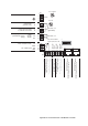
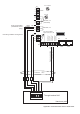


X1
fan 1 (LEFT: supply air,
RIGHT: extract air)
X2
fan 2 (LEFT: extract air,
RIGHT: supply air)
1 48P + 48 VDC 1 48P + 48 VDC
2 GND referential potential (ground) 2 GND referential potential (ground)
3 DRZ 1 rotary speed (Hall) 3 DRZ 2 rotary speed (Hall)
4 0-10 V 1 0...10 VDC 4 0-10 V 2 0...10 VDC
5 MO+1 motor+(6)
6 MO-1 motor-(4)
X3
feed of fan voltage
7 GND potentiometer beginning (1) 1 48P + 48 VDC
8 PTS 1 potentiometer wiper (2) 2 GND referential potential (ground)
9 PTE 1 potentiometer end (3)
10 24P_BYP external relay +24 VDC
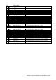
X4
distribution of supply voltage
11 RL_EX external relay, ground 1 N / GND neutral / ground
12 TMP 1
temperature sensor 1 (NTC,
10K)
2 L / 48P* 230 VAC, 50 Hz / 48 VDC*
13 GND ground
* via external switching power
supply
14 TMP 2
temperature sensor 2 (NTC,
10K)
15 GND ground
X5
distribution of supply voltage
16 TMP 3
temperature sensor 3 (NTC,
10K)
1 N / GND neutral / ground
17 GND ground 2 L / 48P 230 VAC, 50 Hz / 48 VDC*
18 TMP 4
temperature sensor 4 (NTC,
10K)
19 GND ground
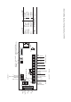
X6 supply voltage of the master, input
1 N / GND neutral / ground
2 L / 48P* 230 VAC, 50 Hz / 48 VDC*
* via external switching power
supply
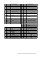
X7
X9
programming interface
1 PE PE through terminal 1 GND OGS
2 PE PE 2 24P’ connected 24 VDC (by the master)
3 PE PE 3 RXD OGS
4 PE PE 4
n.b. not busy
5 TXD OGS
X8 BUS (RS 485)
6
n.b. not busy
1 24P’ + 24 VDC 7 TMS JTAG
2 24P’ + 24 VDC 8 5P_OGS OGS
3
(24P’: BDE) not busy at slave
9 TDO JTAG
4 RS_B dataline B 10 TDI JTAG
5 RS_A dataline A 11 TCK JTAG
6 GND referential potential (ground) 12 / RES JTAG
7 GND referential potential (ground) 13 GND JTAG
8 GND referential potential (ground) 14 5P JTAG
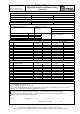
Appendix 5: Terminal Assignment of the Fan Slave Controller