Zeiss Axioplan 2 imaging microscope and Axiovision software Microscopes 1 and 2 in room B501b User Guide Molecular Imaging Unit University of Helsinki www.miu.helsinki.fi 20.5.
1 GENERAL ......................................................................................................................... 1 1.1................................................................................................................... Instrument 1.2.................................................................................................................Reservations 1.3..........................................................................................................
15.2 .................................................................................................................. Computer 15.3 ................................................................................................................ Microscope 15.3.1 .............................................................................................................. General 15.3.2 ................................................................................ Fluorescence light microscopy 15.3.3 ...
1 General 1.1 Instrument This user guide covers the use of Zeiss Axioplan 2 imaging microscope. For more information on each instrument, visit: http://www.miu.helsinki.fi/instruments/index.htm. 1.2 Reservations Instructions for Scheduler online reservation system can be found on the MIU web page: http://www.miu.helsinki.fi/reservations.htm. You can make your reservations three weeks in advance. If you need to cancel your reservation, you have to do it two hours before your reservation starts.
1.7 Sample preparation 1.7.1 Selection of fluorochromes If you want to achieve the best possible resolution, use a fluorochrome whose emission spectrum is covering as short wavelengths as possible. The resolution of the microscope is determined by the numerical aperture (NA) of the objective used and the wavelength of the light detected. The larger the NA, and the shorter the wavelength, the better the resolution.
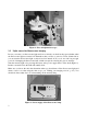
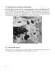
Figure 1. Zeiss Axioplan microscope. 2.2 Light source for fluorescence imaging In case you want to use fluorescence light and it is not already on, check in the paper calendar when the fluorescence light was turned off. Remember that you have to wait for at least 30 min before you can turn the fluorescence light on after it has been turned off. If you do not wait long enough, you risk of damaging the fluorescence bulb, which can explode releasing hot gaseous mercury.
2.3 Light source for transmitted light imaging The black round button labeled “HAL” for the halogen light source is on the right side of the microscope (Figure 3, arrow 1). Voltage of the halogen light can be adjusted with a knob (Figure 3, arrow 2). Remember that while the change of the voltage changes the intensity of the light, it also changes the color: a hot lamp burns bright and blue; a cool lamp burns dim and red.
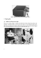
Figure 4. Back side of the Zeiss Axiocam HRc camera 3 Light paths 3.1 Shutters for fluorescence light There are two shutters (Figure 5) which prevent light from mercury lamp from passing to the specimen: a mechanical shutter (1) and an electronic shutter (2). The mechanical shutter blocks light when it is pushed in. The electronic shutter opens and closes by turns when the button labeled “FL” is pressed. Check that the “HAL” button for transmitted light is not pressed when imaging fluorescence.
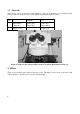
3.2 Push rods There are two push rods near the oculars (Figure 6). The rod on the right (1) is for camera/ocular selection. The rod on the left (2) prevents light from passing through the oculars. Rod IN MIDDLE OUT 1 Oculars 100 % Oculars 50 % Oculars 0 % Camera 0 % Camera 50 % Camera 100 % 2 Oculars closed Oculars open Figure 6. Push rods for camera/ocular selection (1) and for blocking the oculars (2). 4 Filters There are seven fluorescence filters in the microscope.
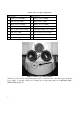
Table 1. Microscope filter configurations. Microscope 1 Microscope 2 1 DAPI (Semrock 5060B) 1 DAPI (Semrock 5060B) 2 FITC (Chroma 41001) 2 FITC (Chroma 41001) 3 TRITC (Chroma 41002b) 3 TRITC (Chroma 41002b) 4 Texas Red (Chroma 41004) 4 Texas Red (Chroma 41004) 5 Narrow GFP (Chroma 41020) 5 DAPI /FITC/TRITC (Zeiss 25HE) 6 CFP (Zeiss 47HE) 6 Narrow GFP (Chroma 41020) 7 YFP (Zeiss 46HE) 7 Yellow GFP (Chroma 41028) 8 Transmitted light 8 Transmitted light Figure 7.
Figure 8. Buttons for changing filter position. Make sure that you are using a filter that matches the spectral properties of the fluorochromes in your sample. The web page of the instrument contains the links to the spectral information of each filter. The triple filter in microscope 2 is not intended for imaging. Instead, for multilabel imaging, use the multidimensional acquisition with individual filters for each label. 5 Objectives 5.
Microscope 2 Mag. Type Working distance (mm) Numerical Aperture (N.A.) Immersion medium 5x Plan-Neofluar 13.6 0.15 air 10x Plan-Neofluar 5.6 0.3 air 20x EC Plan-Neofluar 2.0 0.5 air 40x EC Plan-Neofluar 0.21 1.3 oil 63x Plan-Apochromat 0.19 1.4 oil 100x Plan-Neofluar 0.2 1.
5.2.2 Oil usage Only Zeiss F 158 immersion oil should be used with oil objectives. There are brown oil bottles on the table between the microscopes 1 and 2. Lower the stage to “load position” for more room to operate with oil by pressing the button A in the Figure 10. Drop a small amount of oil on the cover glass. Bring the stage back to the previous level “work position” with the button B in the Figure 10. Figure 10. Stage movement buttons 5.2.
Figure 11. Stage functions 7 Focusing There are focusing knobs on both sides of the microscope. The outer wheel is for coarse adjustment and the inner wheel is for fine adjustment. The actual speed of the stage depends on the magnification of the objective. There is a programmable limit which prevents focusing too close to the sample. When the limit has been reached the “beep” sound can be heard. Sometimes the limit might be set incorrectly.
Figure 12. The button for overriding the focusing limit. 8 Contrasting methods for transmitted light imaging 8.1 Settings Each contrasting method requires a matching position of the condenser. Condenser position can be changed with buttons on the condenser (Figure 13, 1) or within the software. The current position can be seen in the opening (Figure 13, 2). Arabic numbers 1, 2 and 3 are for phase contrast imaging and Roman numbers I, II and III are for DIC-imaging.
Figure 13. Buttons for changing the condenser position (1) and an opening to view the current position (2). There are predefined settings for each contrasting method and objective in software in TOOLS / SETTINGS / WORKGROUP. When choosing a certain setting, the objective will be changed and the condenser will be adjusted automatically. 8.2 Bright-field imaging Bright-field imaging is usually used for histologically stained specimen, but sometimes unstained specimen can also be observed.
8.5 The auxiliary lens for transmitted light The button to control the auxiliary lens is right above the contrasting method indicator (number 2 in Figure 13). The lens should be used when imaging with all but the 5x objective. If the auxiliary lens is in the wrong position, it is impossible to do the Köhler illumination (Chapter 8.6). 8.6 Optimal settings for transmitted light imaging (Köhler illumination) To achieve optimal image quality some adjustments should be made before imaging.
9 Adjusting the oculars Make sure that the oculars are correctly adjusted for your eyes. If you have normal vision, the zero mark on the sides of the oculars should match the white dot. If you wear eyeglasses but want to use the microscope without them, you must adjust the oculars according to your vision. First look at your specimen with your right eye closed (through the left ocular). Slowly turn the eyepiece scale ring until the image is optimally in focus. Repeat with the other eye.
Figure 16. Refresh rate settings for live image. 10.3 Acquiring a single image A single image can be acquired by clicking the snap-button (Figure 17). The new image will open in a new window. Figure 17. Snap-button in Axiovision software. 10.4 Exposure time Click AxioCamHR in the Work area menu (Figure 18) and choose ADJUST tab (Figure 19).
Figure 18. Workarea menu Figure 19. Exposure settings 10.5 White balance White balance adjustment is not needed in fluorescence imaging because the illumination color does not change. However, inappropriate white balance settings may lead to poor image quality. It is recommended to choose 3200K for fluorescence imaging (Figure 20). Correct white balance settings are essential when taking images with transmitted light. The color of halogen lamp depends on voltage.
Figure 20. White balance settings 10.6 Image resolution Click Camera and then AxioCamHR in the Work area menu. Choose FRAME tab. There is a list of available camera resolutions for acquisition. Note that there are four options available for color images: BIN, STANDARD, SCANNED and HIGH SPEED. STANDARD COLOR is faster to take but SCANNED COLOR offers softer image quality, by removing noise. The HIGH SPEED modes produce more noise, but they also retain any sharp edges the objects may have.
Figure 21. Display mapping adjustments 10.8 Acquiring multiple dyes Choose MULTIDIMENSIONAL ACQUISITION in the Work area menu and C tab for color channel settings (Figure 22). Select the dye that best corresponds you fluorochrome from the dropdown list. The pseudo color for the channel will be automatically selected according to the dye, but it can be changed manually. The actual filter is defined separately using HARDWARE SETTINGS (Figure 23).
By clicking MEASURE (Figure 24) the software estimates the suitable time of exposure and the preview live window pops up (Figure 25). Adjust the time of exposure manually if needed and choose OK. Note that exposure adjustment works slightly different from the live window – the image will not get darker if you shorten the exposure time, but it will be noisier. The image intensities are multiplied to fit the monitor - hence the noise. Figure 24. Exposure time setting Figure 25.
The AxioVision software is not able to use decimal numbers on the z slice thickness if the Windows user language is not set to English as it cannot use “,” as a decimal separator. The language setting is tied to the roaming user profile, so it depends on the user. To use decimal numbers in the z slice thickness, change your language setting to English. If you need help with this, ask the MIU staff. 11 Post processing 11.
Drive R: is your personal University network folder. You can access the same folder also from other Windows computers on the campus when logging on with your HYAD-username. "My Documents" is a link to the same folder. You can save your images to USB memory stick. There is an extension cable at the table. 12.2 Transferring images over network 12.2.1 Using MCBSERVER Drive I: is a network drive in Mcbserver1. You can save images temporarily to that folder and pick them up using your own computer.
in the image. If you have adjusted the display mapping curves (Chapter 10.7) you can save them in the exported image by selecting the APPLY DISPLAY MAPPINGS selection. Figure 26. Settings for exporting images. If you have multiple ZVI files you want to export you can use the “Batch >>” button to export them all. 14 Ending your imaging session When you have finished your imaging session you should: Close the electronic fluorescence light shutter (chapter 3.
On working days (Mo-Fr) leave the equipment on if your reservation ends before 16:00. If your reservation begins before 16:00 and ends after 16:00 and you are not present at 16:00, please leave Axiovision software on to show that you will continue your imaging session. If your session ends after 16:00 on a working day, or you are using Axioplan on Saturday, Sunday, or a holiday, you should turn off the equipment unless somebody has a reservation after you. You can check that by opening Internet Explorer.
There seems to be a way to avoid the problem: it occurs only when many image windows are open at the same time in cascade mode (windows partially one on the other). When windows are maximized (e.g. by double clicking the upper bar), the software seems to behave properly. 15.3 Microscope 15.3.1 General Microscope beeps when I try to focus. Check the focusing limit setting and override it if necessary (Chapter 7). The microscope can‟t be controlled with the software.