ZENITH ZF-5 >> Operator’s Manual ZF-5 >> Operator’s Manual WE KEEP ROLLING (434) 202-7790 10517 Critzer Shop Road Afton, VA 22920 >> www.zenithfirearms.
Table of Contents PART 1: Description 01 02 03 04 02 Essential safety instructions 02 1.1 Outlining safety 02 1.2 Safety instructions for handling the ZF-5 03 1.3 Safety instructions for live fire 03 1.4 Exclusion of liability and warranty 03 03 03 04 06 Description of the ZF-5 2.1 Designation 2.2 Intended use 2.3 Functional elements 2.4 Assembly groups 07 08 08 08 Technical description 3.1 Safety features 3.2 Functional elements 3.
>> PART 1: Description 01 ESSENTIAL SAFETY INSTRUCTIONS The ZF-5 is designed and manufactured to precise specifications and recognized safety standards. Nevertheless, using this firearm may result in injury or death of the user, third parties, or damage to the firearm or property. > Follow all instructions in this operator’s manual. Non-compliance may result in injury or death. > Do not handle the firearm if you are tired, feel unwell, or have consumed alcohol, drugs, or medications.
> > > > 1.3 the bolt is in the open position with the safety engaged. Immediately fix any issue that compromises the safe operation of the firearm. Exposure to exceptional stress such as banging or dropping may have a negative effect on the firearm’s safe operation. If this occurs, have the firearm inspected by the manufacturer or a trained armorer. Do not rely on safety features of the firearm alone. Safety features are not a substitute for careful, correct handling of the firearm.
2.
rear sight diopter drum ejection port front sight cocking tube front takedown pin rear takedown pin trigger group takedown pin push button magazine release trigger guard Figure 2: ZF-5 right side view www.zenithfirearms.
2.
03 TECHNICAL DESCRIPTION The ZF-5 is a compact firearm chambered in 9mm, and capable of semi-automatic or full automatic firing, depending on the model. The ZF-5 utilizes a roller-delayed blowback operating system for exceptional reliability. ZF-5 SPECIFICATIONS Full-sized semi-automatic roller-delayed blowback caliber operating system mode of fire magazine trigger pull safety 9 x 19 mm Parabellum gas-operated roller-delayed blowback semi-automatic 30-round steel 6-8 lbs.
3.1 Safety features The safety selector (see Figure 5, page 8) prevents accidental actuation of the trigger. In the safe position, the selector axle and trigger tail prevent rearward trigger movement. When the safety selector is rotated to the fire position, the trigger may be activated. 3.2 > > > > > > Figure 5: Safe position > > 3.3 Figure 6: Fire position Functional elements The safety selector (see Figure 5, page 8) is used to make the firearm safe and to select the mode of fire.
3.3.1 > ZF-5 operational cycle STEP ONE Feeding: A cartridge is removed from the loaded magazine when the charging handle is released. The bolt group moves forward in the receiver as the recoil spring assembly decompresses. As it passes through the feed lips of the magazine, the top cartridge is stripped from the magazine and travels forward with the bolt to the chamber. > STEP THREE Locking: Before firing, the breech is completely closed and temporarily locked.
> STEP EIGHT Cocking: The trigger assembly is reset to allow follow-up shots. Semi-auto configuration: The bolt carrier group moves rearward under recoil and impacts the hammer, compressing it to the cocked position where it is retained by the sear. Full-auto configuration: The bolt carrier group moves rearward under recoil and impacts the hammer, compressing it to the cocked position. As the bolt carrier moves forward, the hammer begins to follow the carrier until it is temporarily retained by the catch.
04 AMMUNITION RECOMMENDATIONS The Zenith ZF-5 Series is designed to fire high-quality, new production factoryloaded ammunition that meets SAAMI or NATO specifications. It is imperative that ammunition of the correct caliber is used to prevent damaging the firearm and to avoid serious injury or death. While Zenith Firearms recommends using brass-case ammunition, there are types of steel-case ammunition that also function reliably.
>> PART 2: Handling 05 CHECKS 5.1 Completing a safety check Successful completion of the safety check verifies there is no ammunition in the firearm. The safety check is especially important when giving or taking the firearm from someone or when the status of the firearm is unknown. 1. 2. 3. 4. 5. 5.2 Point the firearm in a safe direction. Move the selector lever to the safe position on the trigger group. Remove the magazine from the firearm. Move the charging handle to the rear and lock it in place.
06 PREPARATIONS 6.1 Using the sling 6.1.1 Mounting the sling to the ZF-5 1. 2. Attach the rear sling clip to the rear sling mounting point of the firearm (see Figure 1, page 4). Attach the front snap hook to the front sling mounting point of the firearm (see Figure 1, page 4). 6.1.
6.2 Mounting the Picatinny optic rail Required tools: 5/64 hexagonal Allen wrench The ZF-5 can be equipped with optional optic mounts. 1. Place the optic rail on the receiver, aligning it over the mounting tabs to the front and rear of the ejection port (see Figure 1, page 4). Begin attaching the retainers at the base of the optic rail and secure each with the screws from the top.
6.3 Adjusting the rear sight Required tools: sight adjustment tool Point of impact may be affected by the type of ammunition used. Different types of ammunition can change the elevation and windage of where the projectile strikes. Though the sights can be adjusted to correct this effect, it is recommended that you utilize the same type of ammunition for zero adjustment of the sights as you would in an operational setting. There are two parts of the sight adjustment tool (sold separately): 1.
6.3.1 Sight adjustment Lower elevation: clockwise Raise elevation: counterclockwise Left windage: clockwise Right windage: counterclockwise Sight adjustments are only made to the rear sight assembly. Windage or elevation adjustments require the rear sight to be moved in the same direction the shooter wants the location of the projectile to impact. For example, if the impact is to the right of the intended target, then the sights should be moved to the left.
6.3.2 1. 2. 3. Elevation adjustment Insert the screwdriver portion of the rear sight adjustment tool into the spring cylinder tool. Insertion will bring the tabs towards the center. Insert the complete sight adjustment tool assembly into the top of the rear sight drum, engaging the two notches at the base which have spring-loaded plungers. With one hand pressing down on the spring cylinder tool portion of the rear sight adjustment tool assembly, remove the Phillips screwdriver.
6.3.3 1. Windage adjustment Using the Phillips head screwdriver, locate the locking screw (large Phillips head screw) on the top of the rear sight base and unscrew it a quarter turn. Loosen the screw, but do not remove it. Insert the Phillips head screwdriver into the windage screw on the right side of the rear sight base. Make the appropriate rotational adjustment to the windage screw and remove the tool. Tighten the locking screw on the top of the rear sight base securely. 2. 3. 4.
6.4 Using the ZF-5 with a silencer Firing with a silencer places greater stress on the firearm and contributes to faster wear on internal components, as well as heavier fouling. If the firearm is used with a silencer, it is recommended that the firearm be cleaned every 500 rounds and lightly lubricated more frequently. Heavy lubrication will cause excessive smoking while firing, which may cause eye irritation or breathing difficulties.
6.5 Loading the magazine 6.5.1 1. 2. 3. 4. 5. ! RISK OF FIREARM DAMAGE AND INJURY OR DEATH TO PERSON Damaged, dented, or fouled cartridges can damage the firearm and cause malfunctions, along with serious injury or death. > Only use newly-manufactured factory-loaded ammunition that is in good condition. ! RISK OF FIREARM MALFUNCTION AND DAMAGE An overfilled magazine can lead to malfunctions or damage the firearm.
07 OPERATION 7.1 1. 3. 4. 5. Chambering a cartridge Inserting the magazine Load the magazine (see Section 6.5.1, page 20). Move the safety selector (see Figure 1, page 4) to the safe position. Lock the charging handle to the rear. Insert the magazine into the firearm until the magazine catch engages to secure it properly. Pull down on the magazine to verify that it is locked properly in the magazine well. 2. 7.2 ! 1. 2. 3.
7.3 Firing position and aiming 7.3.1 Firing position ! Figure 18: ZF-5 used at sling length 22 ZENITH ZF-5 >> Operator’s Manual RISK OF INJURY The firearm’s recoil can cause injury. > When firing, pull the firearm firmly into your shoulder if using a stock. If firing as a pistol, push out toward the target against a sling to provide a stable firing platform. > Keep your eye at least 2 in. from the rear sight when firing. > Keep your hands out of the path of the bolt when firing.
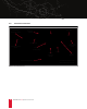
7.3.2 Aiming Correct aiming: The rear sight has four apertures to allow a wider or narrower rear sight picture. The largest aperture is used for rapid target acquisitions at close ranges, whereas the smallest aperture is used for precise aiming. aiming point aperture diopter drum symmetrical gap front sight blade CORRECT! Figure 19: Point of impact centered for the ZF-5 shooting left shooting right shooting low shooting high Figure 20: ZF-5 aiming errors www.zenithfirearms.
7.4 Firing 7.5 7.4.1 Firing in the semi-auto position 1. 1. 2. 3. 4. 5. Prepare the firearm for firing. Chamber a cartridge (see Section 7.2, page 21). Using two hands, firmly grasp the pistol grip with one hand and the handguard with the other (not the magazine). Firing while holding the magazine may cause malfunctions. Aim (see Section 7.3.2, page 23). Move the safety selector (see Figure 6, page 8) to the fire position. ! 6. 7. 24 RISK OF INJURY The firearm’s recoil can cause injury.
7.6 Reloading the ZF-5 ! RISK OF INJURY A firearm with a cartridge in the chamber is a potential source of danger. > Chamber a round of ammunition only immediately before firing. > Unload the firearm immediately after firing. There is no bolt hold open device on the ZF-5, so the bolt will remain forward when the last round in the firearm has been fired. However, there is a tactile trigger click after the last round is fired, indicating an empty magazine. 1. 2. 3. 4. 7.7 1. 2. 3. 4. 7.
08 CLEANING 8.1 8.2 General instructions for cleaning ! Frequent cleaning and lubrication provide several benefits: > > > > Allows the firearm to function more efficiently Prevents premature wear Maintains the highest level of reliability Makes the next cleaning easier and less time consuming Clean the firearm each time it is fired and at intervals of 1000 rounds. Cleaning intervals should be every 500 rounds when using a silencer.
12. Push the front takedown pin in the receiver and out the other side (see Figure 27, page 28). 13. Place the takedown pin somewhere safe. 14. Remove the handguard from the receiver (see Figure 28, page 28). 15. The firearm is now disassembled into its major assembly groups (see Figure 23, page 27). ! RISK OF INJURY If the charging handle and bolt group are locked to the rear, the recoil spring is under tension. > Release the bolt group forward before disassembly. Figure 23: ZF-5 assembly groups www.
Figure 24: Steps 4-6 Figure 25: Steps 7-10 Figure 26: Step 11 Figure 27: Step 12 Figure 28: Steps 13-15 28 ZENITH ZF-5 >> Operator’s Manual
8.2.2 1. 2. 3. Disassembling the bolt group Disassemble the firearm into assembly groups (see Section 8.2.1, page 26). Remove the recoil spring assembly from the rear of the bolt carrier (see Figure 29, page 29). Grasp the bolt head in one hand and the bolt carrier in the other, pull out slightly and rotate the bolt head 90 degrees to the right until it releases from the locking piece (see Figure 30, page 29). 4. The locking piece can be removed from the bolt carrier.
8.2.3 1. 2. 3. 4. Disassembling the trigger group Disassemble the firearm into assembly groups (see Section 8.2.1, page 26). In order to remove the trigger pack from the polymer trigger housing, pull the trigger and ease the hammer forward. Remove the 3/32 Allen screw from the selector lever on the right side of the trigger group and remove the right selector lever (see Figure 33, page 30). Rotate the left safety selector to the 12 o’clock position and remove it from the 5. 6.
8.3 Cleaning the ZF-5 Required materials: cleaning kit and oil ! 1. RISK OF DAMAGE Improper cleaning materials and products can damage the firearm. > When cleaning the firearm, use products specified for firearm maintenance. > Do not use any metallic objects, or harsh chemical agents to clean the firearm. > Do not clean the firearm in an ultrasonic bath for long periods of time, or at high temperatures. Doing so may remove the finish or markings from the receiver or other components.
1 2 3 8 4 >1 >2 >3 >4 >5 >6 >7 >8 >9 cocking tube support inside of receiver recoil spring assembly bolt head assembly locking piece firing pin spring firing pin body (leave end dry) bolt carrier trigger pack components Figure 37: ZF-5 lubrication points 32 ZENITH ZF-5 >> Operator’s Manual 5 6 7 9
8.4 Assembling the ZF-5 8.4.1 Assembling the bolt group 1. 2. 3. 4. 5. Place the firing pin spring over the firing pin and place both inside the rear of the locking piece. With the lug of the locking piece facing down, hold it with your left hand. With your right hand, hold the bolt carrier. Insert the locking piece into the bolt carrier and push inwards against the tension of the firing pin spring and rotate the locking piece 45 degrees to the left (see Figure 38, page 33).
8.4.2 1. 2. 3. 4. Assembling the trigger group Place the trigger pack into the trigger housing, ensuring that it seats flush and that the selector lever opening in the polymer housing aligns properly with the opening on the trigger pack for the selector lever (see Figure 42, page 34). Reinstall the left safety selector at the 12 o’clock position from the left, pressing in and rotating it down to the safe position (see Figure 43, page 34).
8.4.3 1. 2. 3. 4. 5. 6. 7. 8. 9. Reassembly Move the charging handle to the forward position. Assemble the bolt group (see Section 8.4.1, page 33). Insert the bolt group into the receiver (see Figure 46, page 35). Ensure that the hammer is cocked, and reattach the trigger group to its mounting point on the rear of the magazine well, and reinsert the trigger group takedown pin (see Figure 47, page 35).
09 TROUBLESHOOTING: PROBLEMS AND SOLUTIONS Troubleshooting malfunctions that exceed the scope of this manual will void the firearm’s warranty. Only Zenith Firearms-authorized armorers may diagnose and address more serious malfunctions in the firearm. ! RISK OF INJURY OR DEATH In the event of a malfunction, the firearm may be loaded even if you expect it to be unloaded. > In the event of a malfunction, treat the firearm as if there is a round of ammunition in the chamber.
ZENITH FIREARMS LIMITED LIFETIME WARRANTY This express warranty is provided to the private, non-commercial, original owner of the firearm for his or her lifetime. The warranty covers Zenith’s line of firearms, manufactured in the USA, and provides a remedy for manufacturer defects. Repair or replacement of the product is at the discretion of Zenith Firearms. REGISTER YOUR ZF-5 ONLINE: WWW.ZENITHFIREARMS.COM/WARRANTY YOUR OBLIGATIONS: WARRANTY CLAIM PROCEDURES: 1. 1.
ZF-5 FIRING LOG Date purchased: ___________________ Purchased from: _________________________________ Serial #: ________________________________________________________________________________ date 38 user rounds fired ZENITH ZF-5 >> Operator’s Manual total rounds fired notes / repairs
date user rounds fired total rounds fired notes / repairs www.zenithfirearms.
date 40 user rounds fired ZENITH ZF-5 >> Operator’s Manual total rounds fired notes / repairs
ZENITH ZF-5 >> Operator’s Manual ZF-5 >> Operator’s Manual WE KEEP ROLLING (434) 202-7790 10517 Critzer Shop Road Afton, VA 22920 >> www.zenithfirearms.