
Service manual

CM150 3-1 GA - SERVICING
SERVICING
GENERAL INFORMATION
NOTE: 19" and 20" GA1 chassis is a line connected
chassis. When servicing chassis, use an isolation
transformer to prevent possible shock hazard!!
The 25" and 27" GA2 and GA3 chassis has an
isolated supply.
Servicing the GA is the same as with other single board
chassis. If the set is dead, check the power supply first.
First the standby voltages, then the switched voltages.
If the switched voltages do not appear check the power
“On” circuit.
If the power supply is OK and the set will turn on, then
the horizontal sweep needs to be verified next. Is the
horizontal drive available from the video processor? If
the sweep system does not start-up, sweep derived volt-
ages will not be generated.
If sweep and high voltage is OK and video or audio are
missing, then those circuits and the tuner need to be
analyzed.
If the receiver is working but some feature or accessory
is not working, check the Service Menu.
WARNING: If the power supply is operational and the
set still goes into Shutdown or shuts off, this
means that the vertical sweep or X-ray
protection is being activated by the micro.
Check for vertical pulse at the micro (IC6000)
pin 2, or the HV Shutdown Circuit. The set will
not turn on again unless the micro is reset by
unplugging the AC line cord.
The Vertical CRT Deflection Circuit must work in order to
generate the Vertical (Pulse) Signal, if not, the Vertical
Protection Circuit will be activated by the micro and
the set will shutdown. In case of X-RAY protection acti-
vation, check the +130V source first and then the shut-
down network. To turn it on again, reset the
microcontroller or unplug the set.
If the sweep and high voltage is OK and video or audio
are missing, then those circuits and the tuner need to
be checked.
HIGH-VOLTAGE AND X-RADIATION PROTECTION
A potential source of X-rays is the picture tube, if the
high-voltage (HV) is out of specification. When the HV
is operating properly, there is no X-radiation. For the
GA chassis family, the HV has no adjustments. A HV shut-
down circuit is used to prevent excessive HV and X-ray
emissions.
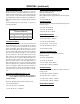
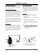
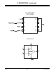
THEORY OF OPERATION (SHUTDOWN CIRCUIT)
The HV shutdown circuit appears on sheet 4 and sheet 5
of the schematics for 9-1869/71, 9-1789/91 and 9-
1996/97 respectively. The basic HV shutdown circuit is
illustrated below.
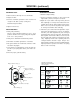
This circuit basically monitors the sweep, pulse voltage
derived from the sweep transformer (TX3202 pins 7 & 9
in GA 19/20”; GA1 or TX3204 pins 5 & 6 in GA 25/27”;
GA2 and GA3. This voltage is rectified and applied to a
9.1 V zener diode (DX3003 in GA 19/20”; GA1 or ZDX3004
in GA 25/27”; GA2 & GA3). When the HV reaches its
maximum allowed value (see table below) the zener di-
ode conducts, the voltage on pin 29 of the video pro-
cessor (ICX2200) increases until it reaches the thresh-
old voltage of 3.5 VDC, and shuts down the TV.
If the shutdown circuit has operated, the microcontroller
will prevent the TV from being turned on again, without
first having to unplug and plug the AC cord to reset the
microcontroller.
TIP: Make a momentary short circuit between the
OUTPUT and GND of the IC6002 (RESET CIRCUIT),
this will reset the microcontroller IC6000.
NOTE: In GA 19/20” or GA1 only, the R3212 is used for
the CRT heater and the shutdown circuit. So if
the video output board is unplugged from the
CRT, the voltage on pin 29 of ICX 2200 will be
increased, and the shut down circuit will activate.
If it is required to test the module without the
CRT or without the video output connected, then
add a load of 9 OHMS 5% 10W WIREWOUND
RESISTOR between pins 9 & 10 of the wireless
socket at the video output board.
SECTION 3
SERVICE INFORMATION
GA1
ICX2200
P29
RL
C
GND
DX3003
DX3002
FROM_RESISTOR_DIVIDER
GA2 & GA3
ICX2200
P29
RL2
C
GND
ZDX3004
DX3005
RL1
FROM_RESISTOR_DIVIDER
GA Shutdown Circuits