
Service manual

CM150 3-2 GA - SERVICING
SERVICING (continued)
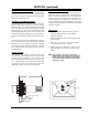
HV MEASUREMENT PROCEDURE
Apply signal through the video generator, or tune the
TV color receiver to crosshatch pattern. Connect an ac-
curate HV meter between the picture tube anode and
chassis ground. Access Video Menu and adjust Bright-
ness and Contrast controls for minimum screen luminance.
Wait until the Video Menu or display disappear. Read HV
meter.
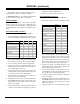
The HV maximum value for each chassis is specified in
the following table:
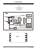
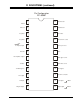
SERVICING THE MODULE
After a module is serviced, access the Service Menu and
check that all items are set properly. When the factory
mode is off only the first seven items in the Service
Menu are available. Place factory mode to 1 to see all
Service Menu adjustments. Be sure the factory mode is
set to 0, which is Off, when the Service Menu is exited.
Also make sure that item 04 LEVEL is set to match the
Level as indicated on the model number sticker on the
back of the set. The Level is changed by placing a short
across pins 3 and 4 of connector 4G9 on the main mod-
ule. Then using the remote control, bring up the Service
Menu and select item 04. Press the adjust button to
make a change. Be sure to remove the shorting jumper
when the adjustment is completed. Confirm that item
#25 is set correctly to match the set being serviced! If
not, and No Audio condition will arise.When in the Pri-
vate label mode, the set will only respond to IR code
121. .
SERVICING THE POWER SUPPLY GA1 19”/20”
NOTE: Use an isolation transformer when servicing 9-
1869, 1870, 1871, 1871-01 and 1950 chassis !!
STANDBY VOLTAGES
Check the Standby Voltage at the following points:
+13 volts DC at CX3411
+12 volts DC at pin 1 of ICX3402
+5 volts DC at pin 3 of ICX3402
POWER ON (9-1869/70/71 AND 9-1950)
Keyboard input at IC6000 pin 7 and 8
IR input at IC6000 pin 15
Power “On” output at IC6000 pin 32
Base of QX3402 power supply switching transistor (about
0.7 volts).
+5 volts IC6000 pin 27
SWITCHED VOLTAGES
Turn the set On and check the Switched voltages at the
following points.
+130 volts DC at FX3402
+150 volts DC at CX3406
+180 volts DC at + of C3207
SWEEP DERIVED VOLTAGES
+5 volts DC at cathode of ZD3206
+9 volts DC at pin 3 of IC3201
+12 volts DC at + OF CX3213
+14 volts DC at + side of C3222
+25 volts DC at D3202 cathode
+180 volts DC at C3207
SERVICING THE POWER SUPPLY
GA2 & GA3 25”/27” 9-1789/90/91 & 9-1831
Standby Voltages
+150 volts DC at RX3404
+123 volts DC at CX3420
+15 volts DC at emitter Q3403
+5 volts DC at cathode of ZD3401
SWITCHED VOLTAGES
Turn set On and check the Switched voltages at the fol-
lowing points:
+5 volts DC at cathode of ZD3402
+9 volts DC at pin 3 of IC3431
+15 volts DC at collector of Q3404
+15 volts DC at collector of Q3403
SWEEP DERIVED VOLTAGES
+25 volts DC at RX3242
SCREEN B+ VDC HV NOM HV MAX
SIZE
(
0 BEAM
)
KV KV
19 130 +/- 0.8 26.5 27
20 130 +/- 0.8 26.5 27
25 124 +/- 0.5 28.5 29
27 124 +/- 0.5 28.5 29
COMPONENT LEVEL REPAIR