HD Projection Display Installation and Setup Guide for System Installer Model PRO895X ®
SAFETY WARNINGS WARNING RISK OF ELECTRIC SHOCK DO NOT OPEN WARNING: TO REDUCE THE RISK OF ELECTRIC SHOCK DO NOT REMOVE COVER (OR BACK). NO USER SERVICEABLE PARTS INSIDE. REFER SERVICING TO QUALIFIED SERVICE PERSONNEL. The lightning flash with arrowhead symbol, within an equilateral triangle, is intended to alert the user to the presence of uninsulated “dangerous voltage” within the product’s enclosure that may be of sufficient magnitude to constitute a risk of electric shock to persons.
CONTENTS Safety Warnings Safety Warnings . . . . . . . . Installation Overview Installer’s Experience Level Installation Considerations . Power Cord Requirements . . Standard Connections Connecting Computer Video Sources . . . . . . . . . . . . . . 6 Connecting Video and S-Video Sources . . . . . . . . . . . . 6 Connector Pin Wiring Reference . . . . . . . . . . . . . . . . . 7 Connection / Control Panel . . . . . . . . . . . . . . . . . . . 8 Selecting Input Source . . . . . . . . . . . . . . . . . . . .
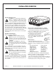
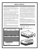
INSTALLATION OVERVIEW Installer’s Experience Level The PRO895X is a sophisticated Entertainment MachineTM. In addition to making the necessary connections, installation will most likely require a series of adjustments to ensure the projected image is not distorted. If these adjustments are not accurate, the operation of the PRO895X could be adversely affected. For this reason, installation and setup should be performed by a qualified service person and should conform to all local codes.
SPECIFICATIONS PRO895X Note: Specifications are subject to change without prior notice. Optical PROJECTION SYSTEM — CRT; 7-inch High Performance Liquid Cooled Tubes, 5-inch active phosphor area, 90 degree deflection angle, Super Oxide Cathodes. LENSES — High resolution color corrected multi-layered coating hybrid lens system. fl.03 Aperture. LIGHT OUTPUT — 700 Lumens peak light output.
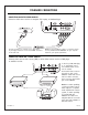
STANDARD CONNECTIONS CONNECTING COMPUTER VIDEO SOURCES Connect a video source such as a computer: PC, Laptop, or Notebook type. To hook up a laptop or computer, use a cable with a 15-pin D-type connector on one end and BNC connectors on the other end. Note: Any special adapters, cables, or connectors shown are not provided with the PRO895X. See your computer dealer for your special requirements.
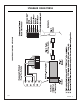
CONNECTOR PIN WIRING REFERENCE STANDARD CONNECTIONS 3276-A PAGE 7
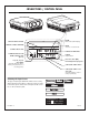
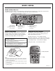
CONNECTIONS / CONTROL PANEL ENTER Shows Source/Time Display SELECTS MENU OPTIONS REMOTE CONTROL WINDOW MENU Accesses on-screen menus S-VIDEO INPUT JACK POWER ON INDICATOR COMMUNICATIONS PORT INTER-CONNECT JACK (RJ-11) POWER On/Off Switch Red, Green, Blue (RGB) Horizontal/Vertical input jacks Loop Out, Loop In, Setup Switch (Set LOOP switch to “Out” if routing composite video to a second projector.) COMPOSITE VIDEO INPUT COMPOSITE VIDEO LOOP OUT JACK (Set LOOP switch to “Out” if using loop through.
REMOTE CONTROL REMOTE CONTROL MBR3470T The MBR3470T remote control is used specifically for servicing and setup adjustment. It provides the special functions needed for geometry, convergence, and system setup that other remotes cannot perform. Red, Green, Blue Selects formats, sets Floor/Ceiling or a specific color convergence. Vertical and Horizontal Adjusts selected geometry/convergence characteristics. Adjustment Select Keys Adjusts selected geometry/convergence characteristics.
PRODUCT OVERVIEW The PRO895X HD Projection Display system is a high resolution multiple signal format display monitor. It uses 7” high performance liquid cooled CRTs. Each CRT has a 5” active phosphor area and a 90 degree deflection angle. The CRTs use high-resolution color corrected multi-layered hybrid lens assemblies. Horizontal scan frequency is from 15 to 40 KHz. Vertical scan frequency is from 40 to 100 Hz. Video system signal bandwidth is 35 MHz.
REAR VIEW Be sure to read and understand the setup section before you attempt to install a PRO895X system; you will find tables and examples of the required installation data for a successful installation. Also, the user Operating Guide and Warranty is included with the PRO895X. Read the user menu section to understand the features and functions for normal system operation. There are no field required adjustments to the service menu.
TOP / INSIDE VIEW PAGE 12 206-3634
SETUP REMOTE CONTROL The PRO895X is supplied with the MBR3470T / 3468PT and a universal customer remote control. For most servicing situations, the MBR3470T / 3468PT is required. The MBR3470T / 3468PT has the special functions needed for geometry / convergence adjustments and system setup functions which the Universal customer remote cannot perform. When using the MBR3470T / 3468PT, press the Convergence Setup Mode Switch. The SETUP mode is only for PRO895X setup / convergence use.
SETUP MODE NOTES AND CAUTIONS 1. When you enter the setup mode, the system is in the “Geometry Mode” (the shape controls adjust all three colors at the same time). To adjust an individual color (i.e. Red to adjust SKEW), you must press the “Red” key. This will put the system into the “Convergence Mode” (the shape controls adjust one color at a time). To return to the Geometry Mode, you must press the “Red” key a second time. 2.
SPECIFICATIONS FOR RGB SYNC INPUTS Version 2.1 December 21, 1995 I. SYNC INPUTS There are three Sync signal inputs for use with RGB sources: 1. SYNC-ON-GREEN (SOG) - - this is through the Green video input BNC jack, terminated 75 ohms. 2. HORIZONTAL/COMPOSITE (H / Comp) - - through a BNC jack on the 9-1515 Combo module, software switchable termination 2K/75 ohms. 3. VERTICAL (V) - - through a BNC jack on the 9-1515 Combo module, software switchable termination 2K/75 ohms. II. COMPATIBILITY 1.
NOTES PAGE 16 3276-A
SCREEN SIZE SELECTION Courtesy of Draper Shade & Screen One of the most important decisions in screen selection is to determine the correct size of screen based upon1. The dimensions of the audience area. 2. The projection format, or formats, to be used. In some situations, these two questions yield the same answer; in others they do not and compromises must be made.
SETUP AND ALIGNMENT PROCEDURE PROCEDURE OVERVIEW There are several situations to consider when performing the setup procedure for the PRO895X System. The setup procedure will vary depending on the required physical and signal configuration. The simplest setup is that of a “factory configured” projector which will use the preset conditions. Factory configured means it has been aligned for ceiling/front projection and a 80” wide display at a projected distance of 96 3/8”. (See pages 20 and 21.
SETUP REFERENCES 9 - 1505 Module Top View 9 - 1510 Module Setup Menus 9 - 1509 Module Top Edge 206-3634 PAGE 19
PHYSICAL SETUP EXAMPLES OF DISPLAY SETUP DISTANCES AND CENTER POINTS Screen Width 48” 60” 80” 96” 120” 144” 160” 200” “A”* Projection Distance 58 5/8” 72 7/8” 96 3/8” 115 1/4” 143 1/2” 171 7/8” 190 5/8” 237 7/8” “B” Display Center 26 3/8” 30 3/4” 38” 43 5/8” 52 3/8” 61” 66 3/4” 81 1/8” “Peerless” Mount Center 11” 11” 11” 11” 11” 11” 11” 11” PHYSICAL SETUP TO THE SCREEN (for all aspect ratios) 1. Set distance “A” according to the selected display width (* or calculate the distance in inches “A” = 1.
SYSTEM ALIGNMENT Mount Bracket Center 11" from Front Panel Under the Green CRT Center 11 Text continued from page 18 III. PRELIMINARY ALIGNMENT SETUP The following procedures are intended for complete “Geometry/Convergence” setup. Use the customer’s signal for doing phase, and size adjustments. You can use the internal patterns for shape and convergence if the customer signal sources do not have a cross-hatch pattern. b. Set Vertical DC centering: Floor: Red = -30; Green = -20; Blue = -30.
SYSTEM ALIGNMENT Continued from previous page Verify spot alignment by rotating Green electrical focus slightly clock-wise to counter clock-wise. The Dot shape should not tail or flair. The bright area should remain in the center of the haloed area. Refer to the figure below. h. Verify spot alignment by rotating Green electrical focus slightly CW to CCW. The Dot shape should not tail or flair. The bright area should remain in the center of the haloed area. i.
SYSTEM ALIGNMENT sharp all the way across (top to bottom and left to right). If not, you can fine adjust with this same procedure. Note: Throughout this procedure pay no attention to the corners of the image. g. Adjust the focus mechanically and electrically to get the best overall image. h. Cover the Green lens and uncover the Red lens. i. Repeat step “b” - “g” for Red. j. Cover the Red lens and uncover the Blue lens. k. Repeat steps “b” - “g” for Blue. l. Re-install PRO895X top cover. m.
SYSTEM ALIGNMENT Continued from previous page IV. Final Detailed Geometry/Convergence Setup Use the video patterns generated by the customer’s signal source for final alignment. If this is not possible, use the internal cross hatch pattern only to do the geometry and convergence. The customer’s signal must be used for blanking, size, centering and phase. 1. Green Geometry Setup a. Return to the geometry and convergence modes and set up the Green display with precision.
SYSTEM ALIGNMENT DIGITAL DISPLAY SETUP PROCEDURE GEOMETRY CONVERGENCE Geometry controls all three colors at the same time. January 1998 Remote Key Adjustment Goal Remote Key 1. SIZE H. Size Set to fill screen at C and D. (Use external source not internal test pattern) 19. T/L KEY V. Top Key 20. T/L PIN V. Top Pin Set for straight top edge, line E-F. 2. SIZE V. Size Set to fill Screen at A and B. (Use external source not internal test pattern.) 21. T/L S V.
PAGE 26 206-3634
SYSTEM ALIGNMENT DIGITAL DISPLAY SETUP PROCEDURE CONVERGENCE OF RED AND BLUE ONTO GREEN It is desirable to Mute color you are not adjusting. Select the color you want to adjust by pressing the RED or BLUE key. Remote Key Adjustment Goal Remote Key Adjustment Goal 1. SMALL ARROWS H. & V. Statics Set center of video for best overlap with Green (this may have to be ‘tweaked’ during this alignment procedure.) 19. S-ING H.
NOTES © Copyright 2001 Zenith Electronics Corporation 206-3700