._Advanced OPERATING Video Imaging GUIDE AND WARRANTY Projection Color TV with MTS Stereo Picture-In-Picture Surround Sound Closed Captions Remote Control Return the Product Registration Card, and your TV co,aid be free!
WARNING: TO REDUCE THE RISK OF ELECTRIC SHOCK DO NOT REMOVE COVER PARTS INSIDE. PERSONNEL. (OR BACK). NO USER SERVICEABLE REFER TO QUALIFIED SERVICE TO PREVENT FIRE OR SHOCK HAZARDS, DO EXPOSE THIS PRODUCT TO RAIN OR MOISTURE.
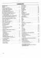
CONTENTS INTRODUCTION Welcome ........................................... Im;tallation Considerations ........................... CONNECTIONS FOR YOUR 'IV Connection Center On Back Of TV .................. Input Sources For Your TV ......................... Step 1. Make Basic Connection To TV ............... Step 2. Make VCR Connections To TV ............... Step 3. Make Super-VHS Connection To TV .......... Step 4. Make Stereo Audio Connection To Audio Amplifier ............................. Step 5.
INTRODUCTION WELCOME Welcome into the fami]Lyof Zenith Color Television owners. This guide provides instructions on how to operate your new TV. It is supplemented by a booklet containing Safety Tips. We urge you to read these publications carefully so that you will receive full enjoyment from your new Zenith TV for many years to come. Send the model number, serial number, and[ date of purchase or original installation, with a full explanation of the problem and the service history.
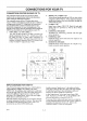
CONNECTIONS CONNECTION CENTER FOR YOUR TV ON BACK OF TV The connection center on the rear of your TV will be similar to the one shown below. Refer to the illustration while reading the following description. Tile connection center of your TV allows three basic "ti_es" of video connections to provide for up to 5 different viewing sources to your TV. Using these five connections, you can choose from a variety of antenna sources and attdio/video components for your viewing pleasure.
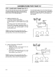
CONNECTIONS STEP 1. MAKE BASIC CONNECTION FOR YOUR TV TO TV There are four basic hook ups to your TV; outdoor antenna (or master antenna) with or without VCR, and cable-TV system with or without VCR. Select the hook up that best fits your needs. See the. following diagrams. A. Antenna Connection Your connection is made to one of the ANT/CABLE jacks on the back of the TV. These. jacks accept 75-ohm cable terminated in an F-type male connector.
CONNECTIONS STEP 1. MAKE BASIC CONNECTION C. Cable-TV Connection to TV If You Do Not Have a Converter/Decoder FOR YOUR TV TO TV (CONTINUED) CH 314 OUTPUT Box: 1. Connect the 75-ohm cable-TV input directly to the ANT/CABLE 1 jack. If You Have a Converter/Decoder Box: I. 2. 3. CONVERIER ! Connect the 75-ohm cable-TV input to the ANT/CABLE 2 jack on the TV. Connect a 75-ohm cable from the LOOP OUT jack on the TV to the IN jack on the decoder/ converter.
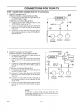
CONNECTIONS ,STEP 2. MAKE VCR CONNECTIONS FOR YOUR TV TO TV STEREO VCR Connections: obtain stereo video tape. STEREO VCR i© You must make the following connections to sound from your TV while playing a stereo It. Connect the VCR RIGHT/LEFT PUT into the VIDEO 1 IN RIGHT jacks on the TV. AUDIO and LEFT 2. Connect VCR VIDEO OUTPUT 1 IN VIDEO jack on TV. into AUDIO I vlo{-o R ! L OUTaudio the VIDEO 0 Operation: To use these VCR connections, VIDEO 1 must be selected from the SOLIRCE MENU.
CONNECTIONS STEP 3. MAKE SUPER-VHS FOR YOUR TV VCR CONNECTIONS In addition to the video connections already described, your TV is also capable of using a Super-VHS VCR as a video source. Refer to the illustration below. 1. Connect the Y/C-VIDEO Output Super-VHS VCR to the S-VIDEO TV. 2. Connect the RIGHT and LEFT AUDIO Output from the Super-VHS VCR to the RIGHT and LEFT (Audio) S-VIDEO INPUT jacks on the TV. (These audio connections must be made in orde_r to receive sound from the VCR.
CONNECTIONS STEP 4. MAKE STEREO FOR YOUR TV AUDIO CONNECTION TO AUDIO AMPLIFIER Using an External Amplifier with Speakers While the TV's Speakers are OFF Using an External Amplifier with Speakers While the TV's Speakers are ON 1. 1. 2. 3. Make the connections to the external amplifier as shown in the diagram below. Place the SPEAKER EXT/INT switch on the TV in the INT position (TV's speakers are ON). Turn the TV ON.
CONNECTIONS STEP 5. MAKE EXTERNAL CONNECTION TO TV SPEAKER STEP 6. MAKE SURROUND CONNECTION TO TV 1. Place the SPEAKERS in the INT position. 2. Connect the two external speaker terminals. Observe polarity of the connections; silver speaker wire to the red terminal and copper speaker wire to the black terminal. Use 8-ohm speakers only. Place the SPEAKERS switch on the back of the TV in the EXT position.
CONNECTIONS STEP 7. MAKE CONNECTION FOR YOUR TV TO FIXED AN JACKS The small panel of three output jacks on the back of your TV provide "fixed" Audio and Video output. This means that whatever is currently being viewed on your TV, regardless of the source, is alsa provided as baseband video and audio to these jacks. F VIDEO 1Usethese standard phono jacks to send fixed-level audio ;and video signals to another component for recording or viewing purposes.
THE FIRST TIME YOU OPERATE YOUR TV STEP 1. CONNECT THE POWER Plug your TV into an unswitched AC power source. The switched AC outlets found on some video equipment will not continue supplying power to the TV once the equipment is turned off. If the power to the TV is interrupted, you will have to set the c_ock in the TV to the current time. :STEP 2. TURN TV ON Turn the TV ON by pressing OFF-ON. STEP 3.
THE FIRST TIME YOU OPERATE YOUR TV STEP 4. USE AUTO CH. (Channel) SEARCH (CONTINUED) f _Lrfo CH.SEARCH HAS O3MP DE'I'ERMI NING "TUNING BAND TUNING BAND TUNING CH _'1 BAND ,... STEP 5.
OPERATING YOUR TV BASIC TV OPERATIONS / Selecting Channels Using CHANNEL Up/Down: You may select a channel through channel scanning by using CHANNEL Up/Down keys. Only channels stored in the channel scan sequence _.n be selected. CH2 STEREO L Selecting Channels by Using Numbers on Remote: Press the numbers corresponding to the channel desired, then press ENTER. Any channel in the band chosen can be selected through direct number entry.
GETTING TO KNOW YOUR TV LOCATION OF USER ITEMS J CONTROL PANEL (On top of TV) BUILT-IN SPEAKERS REMOTE CONTROL (Point toward TV screen) Front View of TV 2 CONNECTION CENTER FIXED JACKS A/V J k "_ hE3 [] Rear View of TV 2_ 4-1 POWER CORD ]ENTRY
GETTING CONTROL TO KNOW YOUR TV PANEL Refer to the illustration below while reading the descriptions of the TV controls. 1. ADJUST (ADJ) Left/Right or <-"/--_ Press during on-screen menu operation to see information/status display for selected option. Press again to adjust the selected menu option. 2. 3. SELECT or ik/y Press during on-screen menu option. MENU 4o Press once to ,;ee a menu. Press repeatedly quence through the available menus. ENTER menu operations 6. to select a to se.
REMOTE CONTROL MODEL MBR3430 OPERATION Tl_e multi-brand remote control supplied with your new Zenith TV allows you to operate most models of infrared (IR) remote-controlled TVs, VCRs and cable-TV decoders, even if they are all different brands. In this way, it takes the place of the several remote controls previously needed. CHOOSE THE OPERATING Your multi-brand remote has already been programmed to operate your new Zenith TV, a Zenith manufactured cableTV decoder and a Zenith VHS VCR.
REMOTE CONTROL MODEL MBR3430 TV OPERATIONS The following functions and operations apply to your Zenith TV. The remote control must be in the TV mode to operate your TV. MODE The VOLUME control will always, adjust the TV volume regardless of the selected operating mode of the remote. t Press repeatedly to select the TV mode of operation. TV OFF/ON Used to turn TV ON or OFF. For optimum performance, point the remote control toward your TV. Lights when TV mode of operation is selected.
REMOTE CONTROL MODEL MBR3430 VCR OPERATIONS The following functions and operations apply to Zenith VCR models built after 1988. The remote control supplied with your VCR may have keys not duplicated on the new remote. If these functions are desired, the original remote control will have to be used. For complete details on how to operate your Zenith VCR, refer to the operating guide supplied with it. The remote control must be in the VCR mode to operate your VCR.
REMOTE CONTROL MODEL MBR3430 CABLE-TV OPERATIONS The remote control must be in the CABLE mode to operate your cable-TV decoder'. The VOLUME control will always adjust the TV volume r,zgardless of the selected operating mode of the remote. The following functions and operations apply to a Zenith cable-TV decoder. The remote control supplied with your cable-TV decoder may have keys not duplicated on the new remote. If these function,; are desired, the original remote control will have to be used.
REMOTE PREPARATION CONTROL MODEL MBR3430 FOR USE Batteries are provided with this remote, but you must install them before using the remote. INSTALLING BATTERIES CAUTIONS: When the effective operating range of your remote becomes _Loticeably shorter, replace the batteries with two (2) high quality, alkaline, size A_Z_Abatteries. Do the following steps: * Do not place heavy objects on top of the remote control buttons. Prolonged accidental operation of the remote control will shorten batteu€ life.
REMOTE PROGRAMMING THE REMOTE CONTROL MODEL CONTROL Before using your new remote control, it must be programmed to recognize the brands of equipment it will be used to operate. If you are using a Zenith TV, Zenith VHS/VCR or a Zenith cable-TV decoder, it has already been programmed for you. Otherwise, follow the steps below. 2. NOTE: The remote control can only be used to operate one VCR, one TV and one cable-TV decoder at a time.
REMOTE CONTROL MODEL MBR3430 I"V,VCR AND CABLE'-TV OPERATING Table 1. TV Codes by Brand TV Brand Name Code TV Briand Name Table 2. VCR Codes by Brand Code Admiral Admiral Akai Amark AOC Bell & Howell Centurion Coronado Curtis Mathes Curtis Mathes Curtis Mathes Daytron Emerson Emerson Emerson Emerson Eraerson Eraerson Fisher Fisher General Electric General Electric General Electric General Electric Goldstar Goldstar Goldstar Hitachi Hitachi Hitachi JVC JVC J.C. Penney J.C. Penney J C. Penney J,C.
ON-SCREEN AVAILABLE MENUS MENUS Your TV is menu operated, that is, adjustments that can be made to the TV appear on the screen in a list of choices you c_a make by using the controls on the front panel of the TV or on the remote control. There are four basic menus: SOURCE, SETUP, AUDIO, and VIDEO. These menus list everything you can adjust to your personal preference or needs. In addition, separate SOURCE and VIDEO menus appear for PIP while PIP is active. SETUP MENU -_ AUTO CH. SEARCH CH. ADD/DEL CH.
ON-SCREEN SUMMARY OF MENU ITEMS MENUS (CONTINUED) AUDIO Menu BASS: Adjusts the BASS (low frequency) TREBLE: Adjusts the TREBLE BRIGHTNESS: Adjusts the brightness level of black areas in the picture. level. COLOR: Adjusts the intensity of the colors in the picture. (high frequency) level. BALANCE: Adjusts the BALANCE of sound between the left and right speakers for stereophonic programs. TINT: Adjusts the color of the flesh tones.
SOURCE MENU --SOURCE MENU-- ANT/CABLE1 ANT/CABLE2 VIDEO 1 VIDEO 2 S-VIDEO 1 TO SELECT A SOURCE The color for the Channel/Time display, Volume and Muted display will match the color or the source you are watching. The color will also help to identify which source you are watching when viewing PIP. The colors are as follows: Purpose The SOURCE MENU is used to specify the equipment that is being used to supply the video and audio signals. You select the source you want by selecting the SOURCE MENU.
SETUP MENU SETUP MENU -> AUTO CH. SEARCH CH. ADD/DEL CH. LABELS TUNING BAND AUTO FINE 'TUNE CLOCK SET CAPTIONS CH. BACKGROUND PROJO SETUP START SETUP MENU -> CLOCK SET CAPTIONS CH. BACKGROUND PROJO SETUP Setup Menu For Video and S-Video :Sources Main Setup Menu AUTO CH. (Channel) SEARCH 3. Use the AUTO CH. SEARCH feature independently for each ANTENNA or (2ABLE signal source connected to your "]?V. Select one source by using the SOURCE MF',NU (ANT/CABLE 1 or 2) and use ,AUTO CH. SEARCH.
SETUP MENU CH. (Channel) ADD/DEL Purpose Lets you add channels to and remove channels from the active channels found by the AUTO CH. SEARCH option. In this way, you can customize the channels that are accessed through CHANNEL Up/Down. To CH. ADD/DEL is an optional feature. You do not have to activate this feature i.norder to use your TV. Add a Channel to Scan Sequence 1. CH. ADD/DEL should be selected if you followed the "Basic Menu Operation" given in the "OnScreen Menu" section. 2.
SETUP MENU TUNING BAND ]Purpose 2. .Mlows for setting the TV tuner to match your antenna or cable-TV system. If you used the AUTO CH. SEARCH feature, the proper BAND was set automatically for your TV. If you did not use AUTO CH. SEARCH, or you are having difficulty tuning channels, the TUNING BAND may have to be set manually to match your viewing needs. Before Using TUNING BAND Connect and turn ON all external equipment, such as a cable-TV decoder, VCR, etc. Use CH. AUTO SEARCH, if not previously used.
SETUP MENU CLOCK SET To Use CLOCK SET from Remote Control Purpose Sets the clock in the TV to the correct time. After the time is set, the current time will appear on the Channel/Time display whenever the TV is turned on, the channel is changed, or ENTER is pressed. 1. CLOCK SET should be selected "Basic Menu Operation" given Menu" section. 2. Use the numbered enter the current clock. Power Failure Note: The time will have to be reset if power to the TV is interrupted.
SETUP MENU CAPTIONS (CONTINUED) To remove a display that is interfering with captions, press ENTER until the display disappears. Likewise, you can instantly remove any captions by pressing ENTER to call up the Channel/Time display. Wken you press ENTER again, the Channel/Time display disappears and you return to captions. Application Your new TV is able llodecode and display the closed captions and informational text that are broadcast with some TV shows.
SETUP MENU PROJO (Projection) SETUP If there are more than tour lines, each a different color, you must adjust the convergence. Purpose Lets you verify and adjust, if needed, the dynamic color convergence of the TV. 3, Your projection TV has three separate projection picture tubes, one for each primary color: red, green and blue. To obtain a good color piicture, it is necessary that all three colors are aligned exactly. This alignment is called "convergence." 4o 5.
AUDIO MENU AUDIO MENU •->BASS TREBLE BALANCE AUDIO SEQ SURROUND GENERAL L I I I STEREO ON + + R NOTE: All adjustments on the AUDIO MENU are optional. You do not have to use these features in order to use your TV. mm INFORMATION Your TV is equipped to receive Multi-channel Television Sound (MTS) when _.vailable in your area. It can also receive a Second Audio Program (SAP), that is, a program broadcast with two audio portions (two languages). The following modes of operation are available.
AUDIO MENU AUDIO SURROUND Use ADJUST (ADJ) Left/Right to select the speaker audio output mode. You may choose either STEREO, MONO or 2ND AUDIO/SAP. ]IfSTEREO is selected but not received, the following line appears at the bottom of the Use ADJUST (ADJ) Left!Right to adjust the level of Surround sound you wish to obtaia. To decrease (-) Surround sound, press ADJUST (ADJ) Left. To increase (+) Surround sound, press ADJUST (ADJ) Right.
AUDIO MENU AUDIO SELECTION CONSIDERATIONS .f The last line of the Ch_mnel/Time display shows the current audio heard. The display is shown each time you turn the TV ON, change channels, or press ENTER. The audio heard depends on the following: • AUDIO mode selected on AUDIO MENU: STEREO, MONO or 2ND AUDIO/SAP. • • STEREO selected using the AUDIO option on the AUDIO Menu and a stereo siglaal is received; you will hear stereo sound. The Channel/ Tirae display shows STEREO.
VIDEO MENU VIDEO MENU PIP VIDEO MENU -_ CONTRAST BRIGHTNESS COLOR TINT SHARPNESS COLOR TEMP VIDEO FILTER AUTO FLESH PICTURI- PREF G - -4- CONTRAST COLOR TINT PICTURE PREF 4- n R + COOL OFF ON PRESET - n - =_= G t PRESET PIP Video Menu Appears When PIP is ON Main Video Menu Appears When PIP is OFF CONTRAST COLOR Adjusts the overall contrast and color level of the picture. Allows you to change the "color temperalmre" or picture white balance between cooler natural whites and warmer (red) colors.
PIP OPERATION AND CONNECTIONS PIP (PICTURE-IN-PICTURE) Your Zenith TV must be connected to a video component such as a VCR in order to view a different picture in the PIP inset. This video component must be connected to one of the TV's video/audio input jacks (VIDEO 1 IN or VIDEO 2 IN) by using Audio/Video cables.
PIP OPERATIONS AND CONNECTIONS Cable Decoder Connection HOW TO SELECT & PIP SOURCE This illustration shows the connection of both a cable-TV decoder and a stereo VCR to your TV. Using this connection, you are capable of, but not limited to, the following operation: * • • MAIN PICTURE In order to watch a different picture in the PIP inset, you must choose a different source than the one used for your main TV picture.
PIP OPERATIONS To Select Main Picture AND CONNECTIONS Source: PICTURE-IN-PICTURE The source for the maLin picture can be either of the ANT/CABLE connections or any of the VIDEO connections. The following example selects ANT/CABLE 1 for normal television viewing, which is the most common setup. 1. Press light 2. Press MODE button on the remote control until Moving The Pip Inset Use 4-way arrows (ADJ/SELECT) desired corner of the TV screen.
MAINTENANCE CARING FOR YOUR PROJECTION AND TROUBLESHOOTING TV Your projection TV will look better, have a longer life and perform better if you care for it properly. Picture Screen Cleaning Use a soft cloth moistened with warm water and rub lightly in the soiled areas of the screen. DO NOT USE A TISSUE safety, disconnect AC power to your TV. First check to see that the TV is off. For added EXTENDED OR PAPER TOWEL, AS THESE MAY DAMAGE SURFACE.
MAINTENANCE BEFORE CALLING AND TROUBLESHOOTING FOR SERVICE Check these items arm see if you can correct the trouble by changing the adjustment of a control or the setting of a switch. By making these simple checks before calling for service, you may save time and money Problem Try This Picture OK. Poor sound. Re-orient antenna. Check :[or local interference. Try another channel - possible station trouMe. Check AUTOE FINE TUNE and TLINIG BAND options in SETUP Menu. Sound OK. Poor picture.
MAINTENANCE VCR MODE CHART 1. OUTPUT AND TROUBLESHOOTING TO TV FROM ANTENNA OUT JACK ON VCR The operating mode of your VCR determi[nes what type of a program source is provided, and whether the audio is stereo or monaural. Use this flow chart to determine the START) HERE operating status of your VCR, so that you can select the proper viewing source and channel on your TV. Select the VCR output channel (3 or 4) on your TV to view tapes or to see programs selected by using the channel tuner in the VCR.
MAINTENANCE VCR MODE CHART 2. OUTPUT AND TROUBLESHOOTING TO TV FROM AUDIO/VIDEO JACKS ON VCR The operating mode of your VCP. determines wtmt type of program source is provided, _ald whether the audio is stereo or monaural. Use this flow chart to determine the operating status of your VCR, so that you know when to se]Lectthe VCR (or auxiliary) source on your "IV, Use the LEFT and RIGHT AUDIO output jacks on the VCR to get stereo sound. Select STEREO audio mode of operation for the TV by usi.
PRODUCT REGISTRATION CARD You could win a full refund on your new Zenith product. Product Look for the Product Registration The Product Registration Card furnished _Mthyour video product is pre-printed with its Model and Serild numbers. Please fill out the card and raai] it at your earliest convenience. It is imperative that Zenith know how to reach you promptly if we discover a safety problem tlaat would affect you. If the original card ha.
RECOMMENDED ACCESSORIES FOR YOUR I"ELEVISION MBC4OOP 3 FUNCTION MULTI-BRAND REMOTE CONTROL (2 Ib=) WALL MOUNTS (17 Ib=) • Easy to inst_l ff your'IV screen is: Order this model Combining three remotes into one has never been easier, Operate your TV, VCR and cable converter with one remote control. • Electronic mode switching • Easy sat-up: simply • Safe and strong • 5 year warranty • Made in U.S,A.
YOUR ZENITH WARRANTY Consumer Protection Plan for Zenith Projection TV Owner's Responsibility 'Welcome into the Zenith family! We believe that you will be pleased with your new Z_mith Projection TV. Please read this Consumer Protection Plan carefully. It is a "ONE YEAR FULL WARRANTY," plus a limited second year picture tube warranty, as defined under federal law. This warranty gives you specific legal rights, and you may also have other rights Lhat vary from state to state within the U.S.A.
ZENITH ELECTRONICS CORPORATION 1000 MILWAUKEE AVENUE GLENVIEW, ILLINOIS 60025 ]Part No. 206-2588 Printed in U.S.A.