http//www.zenithservice.com SERVICE MANUAL Product Type: Chassis: Manual Series: Manual Part #: Model Line: Product Year: Model Series: P42W46X PLASMA RF-043A P42W46XH 2004 CONTENTS Description of Controls .................................................4 Product Specifications ..................................................7 Adjustment Instructions ................................................8 Diagrams ...................................................................23 Parts List ..........
PRODUCT SAFETY GUIDELINES IMPORTANT SAFETY NOTICE This manual was prepared for use only by properly trained audio-visual service technicians. When servicing this product, under no circumstances should the original design be modified or altered without permission from Zenith Electronics Corporation. All components should be replaced only with types identical to those in the original circuit and their physical location, wiring and lead dress must conform to original layout upon completion of repairs.
TABLE OF CONTENTS DESCRIPTION OF CONTROLS ...........................................4 SPECIFICATIONS.................................................................7 ADJUSTMENT INSTRUCTIONS ..........................................8 TROUBLE SHOOTING GUIDE ...........................................12 BLOCK DIAGRAM...............................................................23 EXPLODED VIEW...............................................................26 EXPLODED VIEW PARTS LIST ........................
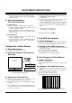
DESCRIPTION OF CONTROLS Controls - This is a simplified representation of front panel. Here shown may be somewhat different from your TV. - This manual explains the features available on the P42W46X. Front Panel Controls ON/OFF TV/VIDEO ON/OFF Button MENU VOL MENU Button Remote Control Sensor TV/VIDEO Button Power Standby Indicator Illuminates red in standby mode, Illuminates green when the TV is turned on.
DESCRIPTION OF CONTROLS Connection Options L / MONO A/V INPUT2 VIDEO S-VIDEO S-VIDEO Input A connection available to provide better picture quality than the video input. VIDEO Input Connects the video signal from a video device. R AUDIO AUDIO Input Use to connect to hear stereo sound from an external device. Monitor Output Connect a second TV or Monitor. DVD/DTV Input (Component 1-2) Connect a component video/audio device to these jacks.
DESCRIPTION OF CONTROLS Remote Control Key Functions - When using the remote control, aim it at the remote control sensor on the TV. MUTE Switches the sound on or off. TVVIDEO Selects: TV, Video 1-2, Component 1-2, RGB, and DVI input sources. MUTE POWER TV/VIDEO MULTIMEDIA MTS CAPTION ARC MENU MULTIMEDIA Selects: Component 1-2, RGB, and DVI input sources. CAPTION Selects CAPTION mode. VOLUME UP/DOWN Increases/decreases the sound level. Selects a menu item.
SPECIFICATIONS MODEL P42W46X Width (inches / mm) 48.4 / 1210 Height (inches / mm) 27.6 / 701 Depth (inches / mm) 11.4 / 290 Weight (pounds / kg) 66 / 22.
ADJUSTMENT INSTRUCTIONS (2) After installing the Gprobe, [Option -> Connection Setup] or click the icon indicated in the picture and then setup as below the picture. (In case of the port (second one), set to the serial port of the connected PC. The other only have to be set as below the picture.) (3) After finishing inputs, click the button [OK] to complete the connection setup. 1. Application Object These instructions apply to the RF-043A Chassis. 2.
ADJUSTMENT INSTRUCTIONS Each PCB assembly must be checked by check JIG set. (Because power PCB Assembly damages to PDP Module, especially be careful) 5. POWER PCB Assy Voltage Adjustments (Va, Vs Voltage Adjustments) 5-1. Test Equipment : D.M.M. 1EA 5-2. Connection Diagram for Measuring Refer to Fig 5. (Fig 3) 4. HDCP download 4-1. Setting up & Confirming the G-prove : Refer to 3-1 and 3-2. 4-2.
ADJUSTMENT INSTRUCTIONS (2) Supply Gray Pattern (216 Level Full Size Pattern) signal to VIDEO input. (AV2 Input 60Hz) (Refer to Fig. 6) (3) To adjust, stick sensor to 216 Gray Level Pattern, press ADJ key twice(White Balance) on remote control. For adjustment and D, E on reomte control for adjustment mode to select Red Gain and Blue Gain, press VOL +, Key and adjust it until color coordination becomes as below. 2) After turning RV401, voltage of D.M.
ADJUSTMENT INSTRUCTIONS 9. Auto Adjustment Map(RS-232C) 6) If Check Sum is not 53, repeat 3) ~ 4). 7) If Check Sum is 53, DDC data for Analog-RGB input is completed.
TROUBLE SHOOTING GUIDE 1. Power Board 1-1. The whole flowchart which it follows in voltage output state Start check Doesn't the screen whole come out? Yes It is identical with Power Off condition? No Is the Interface signal operated? Yes No Doesn't the low pressure output come out? Yes 1. Check the Power Off condition. Yes Doesn't the St-by 5V signal come out? 2. Check the Interface signal condition.
TROUBLE SHOOTING GUIDE 1-2.
TROUBLE SHOOTING GUIDE 1-3.
TROUBLE SHOOTING GUIDE 2. No Power (1) Symptom ¯ ¯ Does’t minute discharge at module. Non does not come in into the front LED. (2) Check follow No Is plug in power cord? Plug in power cord. Yes Is connect the Line Filter and Power Switch Cable? No Connect Cable. Yes Is connect the Power Switch and Power Board Cable? No Connect Cable. Yes Is normal the Fuse(F101) on Power Board? No Replace Fuse. Yes Is connect the Power Board and 7P of VSC Board Cable? No Connect Cable.
TROUBLE SHOOTING GUIDE 3. Protect Mode (1) Symptom After once shining, it does not discharge minutely from module ¯ The Rely falls(The sound is audible “click”) ¯ It is converted with the color where the front LED is red from green. ¯ (2) Check follow Is normal the Power Board? No Is output the normality Low/High voltage except Stand-by 5V? No Replace Power Board. Yes Is normal the each connector? No After connecting well each connector, the normality it operates? No Replace connector.
TROUBLE SHOOTING GUIDE 4. No Raster (1) Symptom ¯ ¯ Does’t minute discharge at module. It maintains the condition where the front LED is green. (2) Check follow Is normal the Power Board? No Is output the normality Low/High voltage except Stand-by 5V? No Replace Power Board. Yes Is normal the each connector? No After connecting well each connector, the normality it operates? No Replace connector.
TROUBLE SHOOTING GUIDE 5. In case of occur strange screen into specific mode 5-1. In case of does’t display the OSD (1) Symptom ¯ ¯ LED is green The minute discharge continuously becomes accomplished from module (2) Check follow Is normal the LVDS cable? No Yes Is the LVDS cable connected well? Replace cable. No Cable inserts well. Yes Is normal the VSC Digital Board? No Operates the Thine Yes IC(IC1100)? Operates the IEP(IC500)? No Replace Thine IC(IC1100).
TROUBLE SHOOTING GUIDE 5-2. In case of does’t display the screen into specific mode (1) Symptom ¯ The screen does not become the display from specific input mode (RF, AV, Component, RGB, DVI). (2) Check follow ¯ ¯ Check the all input mode should become normality display. Check the Video(Main)/Data(Sub), Video(Main)/Video(Sub) should become normality display from the PIP mode or DW mode.
TROUBLE SHOOTING GUIDE (5) In the case of becomes unusual display from RF, AV, Component 480i mode Is normal the VPC3230? No Is normal the Input voltage, IIC Communication and HV sync? No Is normal the Input voltage, IIC Communication and HV sync? No Is normal the Input voltage, IIC Communication and HV sync? No Replace IC Yes No Is normal the S2300? Replace IC Yes No Is normal the Scaler? Replace IC (6) In the case of becomes unusual display from Component DTV mode Is normal the 74LS123? No
TROUBLE SHOOTING GUIDE (7) In the case of becomes unusual display from RGB DTV mode Is normal the CXA2101? No Is normal the Input voltage, IIC Communication and HV sync? No Is normal the Input voltage, IIC Communication and HV sync? No Is normal the Input voltage, IIC Communication and HV sync? No Replace IC Yes Is normal the M52758? No Replace IC Yes No Is normal the Scaler? Replace IC (8) In the case of becomes unusual display from RGB PC mode Is normal the M52758? No Is normal the Input v
TROUBLE SHOOTING GUIDE 6. In case of no sound (1) Symptom ¯ ¯ LED is green Screen display but sound is not output (2) Check follow Is normal the SPK cable? No Is the SPK cable connected well? Yes Replace SPK cable No Yes Is normal the RGB/DVI sound? Cable inserts well. No Is the Flat cable connected well? Yes No No Cable inserts well.
- 23 - 24LC21 RX/ TXC 24LC21 74HCT08 Co mp _Y YCin4 Vin4 TU_Sub TU_Main Text _V Main_YC HYV641620 SRAM SDA6001 Text Processor VPC3230 (S) Video Decoder VPC3230 (M ) Video Decoder Sid e - AV BOARD Co mp _480i CVBS S-VHS Vin5 YCin5 CXA2069Q SWITCH Main_V Main_YC Main_V M52758F Sw it c h RGB_Dat a AM29LV160 F-ROM HY57V64322 SDRAM ( 8MB) YCb Cr S2300 / DeInt erlac er 8 DVI_Dat a g m 1601 Sc aler ( Malib u) ADC w/ PLL 10 24 ZHINE Po s-t p ro c es sing Blo c k is o m it t ed .
IIS RGB DTV IIS HV IIS Tx - 24 - Sid e S-VHS Side-CVBS Sid e A/ V RF S-VHS CVBS OUT CVBS IN ( DVD/ DTV) Co m p 2 ( DVD/ DT V) Co m p 1 24LC21 24LC21 Y/ CIN2 VIN2 Tuner ( S) CXA2069Q 74HCT08 ST3232C 74ACT253 Tuner ( M) Y/ CIN1 MNT_OUT VIN1 Co mp 2 Co mp Analo g BOARD DVI ( PC/ DTV) RGB ( PC/ DTV) RS232 WIRE IR Di gt a l BOARD MAIN_YOUT MAIN_VOUT MAIN_COUT CAB_VIN DTV2_Co mp DAC_RGB RGB_DTV M52758FP IC202( MUX) LA7151M DVD2_MAIN DVD_MAIN DTV_Co mp M52758FP IC
NOTES - 25 -
EXPLODED VIEW 300 121 600 601 301 305 304 120 303 302 200 207 202 206 205 530 201 490 204 531 402 580 203 560 410 520 400 570 401 430 - 26 -
EXPLODED VIEW PARTS LIST No. Part No. 120 6401VD0013G SPEAKER ASSEMBLY,FULL RANGE(R) 121 6401VD0013H SPEAKER ASSEMBLY,FULL RANGE(L) 200 6348Q-E058T PDP,42 16:9 852*480 PDP42V60000.
REPLACEMENT PARTS LIST For Capacitor & Resistors, the charactors at 2nd and 3rd digit in the P/No. means as follows; LOCA. NO CC, CX, CK, CN : Ceramic CQ : Polyestor CE : Electrolytic PART NO RD : Carbon Film RS : Metal Oxide Film RN : Metal Film RF : Fusible RUN DATE : 2004.4.8 DESCRIPTION LOCA. NO IC IC100 0IMI623200B IC100 0IMMRAL014B AT24C02N 10SI 2.
REPLACEMENT PARTS LIST LOCA. NO PART NO DESCRIPTION LOCA.
REPLACEMENT PARTS LIST LOCA. NO PART NO DESCRIPTION LOCA.
REPLACEMENT PARTS LIST LOCA. NO PART NO DESCRIPTION LOCA. NO PART NO DESCRIPTION C1256 0CE227VF6DC 220UF MV 16V 20% C301 0CE476SF6DC 47UF MVG 16V M C1257 0CE227VF6DC 220UF MV 16V 20% C303 0CE476SF6DC 47UF MVG 16V M C1259 0CE227VF6DC 220UF MV 16V 20% C315 0CE476SF6DC 47UF MVG 16V M C127 0CE475SK6DC 4.
REPLACEMENT PARTS LIST LOCA. NO PART NO DESCRIPTION LOCA. NO PART NO DESCRIPTION C757 0CE226SF6DC 22UF MVG 16V 20% L804 6140VB0022A COIL,CHOKE CPS 0810 GET 22UH C762 0CE226SF6DC 22UF MVG 16V 20% L805 6140VB0022A COIL,CHOKE CPS 0810 GET 22UH C769 0CE226SF6DC 22UF MVG 16V 20% L806 6140VB0022A COIL,CHOKE CPS 0810 GET 22UH C777 0CE226SF6DC 22UF MVG 16V 20% C778 0CE226SF6DC 22UF MVG 16V 20% C785 0CE335SK6DC 3.
REPLACEMENT PARTS LIST LOCA. NO PART NO DESCRIPTION LOCA.
REPLACEMENT PARTS LIST LOCA. NO PART NO DESCRIPTION LOCA.
MAIN (TOP)
PRINTED CIRCUIT BOARD MAIN (BOTTOM ) MAIN (TOP) TUNER(TOP) TUNER(BOTTOM) POWER S/W(TOP) POWER S/W(BOTTOM) SIDE A/V(TOP) SIDE A/V(BOTTOM) CONTROL(TOP) CONTROL(BOTTOM)