
Owner`s manual

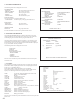

c-1. JVS INPUT TEST
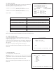
Use the JVS INPUT TEST to test the JVS input.
The hexadecimal input information from the JVS I/O board will be
displayed in real time.
The following information is displayed on this screen.
SYSTEM: System switch input data
PLAYER: Player number and player switch input data
COIN: Slot number and coin input data
ANALOG: Channel number and analog input data
Press the SERVICE and TEST Buttons simultaneously to return to the
JVS Test screen.
JVS TEST
INPUT
TEST
NODE 1/3
SYSTEM 00
PLAYER 1 0000
PLAYER 2 0000
COIN 1 0000
COIN 2 0000
ANALOG 0 0000
ANALOG 1 0000
ANALOG 2 0000
ANALOG 3 0000
ANALOG 4 0000
ANALOG 5 0000
ANALOG 6 0000
ANALOG 7 0000
SELECT
TEST AND SERIVE TO EXI T
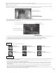
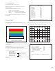
d. MONITOR TEST
Use MONITOR TEST to check the output of the monitor.
Enter MONITOR TEST and the following color bars will be displayed.
1 MONITOR TEST 1/ 2 32
PRESS TEST TO NEXT
Press the TEST Button and the screen will change to the following cross-hatch
screen.
Press the TEST Button to return to the System Test Menu screen.
MONITOR TEST 2/ 2
PRESS TEST TO EXI T
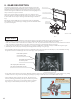
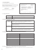
e. SPEAKER TEST
Use SPEAKER TEST to check the output of each speaker by having them each
emit a test sound.
Select each speaker with the cursor and press the TEST Button to turn that
speaker ON or OFF.
When set to ON a test sound will be emitted from that speaker.
It is possible to set multiple speakers to emit the test sound at the same time.
The speakers available to test are as follows.
RIGHT SPEAKER
LEFT SPEAKER
REAR RIGHT SPEAKER
REAR LEFT SPEAKER
CENTER SPEAKER
WOOFER SPEAKER
Move the cursor to EXIT and press the TEST Button to return to the System Test
Menu screen.
SPEAKER TEST
RIGHT SPEAKER OFF
LEFT SPEAKER OFF
REAR RIGHT SPEAKER OFF
REAR LEFT SPEAKER OFF
CENTER SPEAKER OFF
WOOFER SPEAKER OFF
EXIT
SELECT WITH SER VICE AND PRESS TEST
->
Not available these for this
product. Sound is not
emitted even if the setting
is ON.
23