Assembly Instructions 72S3STBNL (Dual Mount Curved Rod) For Spanish and French instructions, start on page 11. Para instrucciones en español y francés, comience en la página 11. Pour les instructions espagnoles et françaises, commencez à la page 11. Before You Begin: Thank you for purchasing this product. Please identify all parts and hardware pieces before you begin. When laying out parts, place them on a soft surface to prevent scratching.
Cleaning Note: Cleaning with a dry cloth may be sufficient, but for other stains or marks wipe gently with a damp cloth. DO NOT use strong detergents or abrasive cleaners, they may damage the surface of this product. Tools Needed - not included List of Parts - NOTE: Product is marked for TENSION INSTALLATION. Before assembling, Make sure that the tube assemblies (B) are at the shortest position by twisting the end of the tubes in the OPPOSITE DIRECTION of the arrow stickers.
For Permanent Mount Installation go to page (6) Step 1 and 2 - Tension Installation • STEP 1: Locate the end cap and mounting bracket labeled (A) and CLICK them together. NOTE: Make sure the directional stickers are pointing in the same direction. • Following the directional s ticker UP ARROW and connect rod (A) to the mounting bracket (A) by pushing the tube into the mounting bracket against the floor until the rod and mounting bracket CLICK together.
Step 3A - Tension Installation • Turn the rod (A) upside down and locate the screw position areas. • Using the included allen wrench (E), LOOSEN the attached set screws (F) to allow rods to expand smoothly. • NOTE: Do not remove t he set screws (F). loosen set screws (F) E A Step 3B - Tension Installation • Insert the end of the 7/8 in. diameter tube assembly (B) into the end of the 1 in. diameter tube (A), fig 1. • Once connected, wipe the rubber pad on each mounting bracket (A and B) clean, fig 2.
Step 4A - Tension Installation • NOTE: The rod should be installed with the set screws (F) on the bottom side and the curve facing out of the tub. • PERSON 1: While facing the tub hold the left mounting bracket (A) and firmly press against the left wall. • PERSON 2: Hold the right mounting bracket (B) and firmly press against the right wall. PUSH PUSH RECOMMEND PERSON 1 (LEFT) PERSON 2 (RIGHT) Step 4B - Tension Installation • NOTE: Make sure the rod is level and adjust if needed.
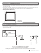
Measurements: Permanent Installation • Start by facing your tub. Measure the width of your tub opening. • From the front left side of the opening, measure 62 in. above the top of the tub ledge. Place a small mark on the edge of the wall. • Measure the appropriate distance (from the chart below) from the 62 in. mark towards the back of the tub. Maintaining the same 62 in. height, make another mark. This is where you will apply the rod. • Repeat on the right side of your tub.
Step 2 - Permanent Installation • Align the top hole of the left mounting bracket (A) to the top wall anchor (D) that is now in the wall. • Rotate a pencil through the bottom hole of the left support to mark drilling location. NOTE: MAKE SURE THE CENTER DIVIDER IS PERFECTLY HORIZONTAL AND SCREW HOLES ARE POSITIONED VERTICALLY. • Drill the bottom hole where marked. With your hammer, gently tap the wall anchor (D) into the hole all the way so the edge is flush to the wall.
Step 3 - Permanent Installation • Install the left mounting bracket (A) using the mounting s crews (C). • Repeat this step on the other side with right mounting bracket (B). A D C Step 4 - Permanent Installation • Slide the end caps (A and B) onto the tubes (A and B), following the ‘UP’ position mark. NOTE: Do not attach the end caps to the mounting brackets.
Step 5 - Permanent Installation • Locate the rod and mounting bracket labeled (A). Follow the ‘UP’ position mark on the mounting bracket. • Following the directional stickers UP ARROW, connect rod (A) to mounting bracket (A). P ress firmly until the rod a nd mounting bracket CLICK together. • Push end cap (A) into place. Follow the ‘UP’ position mark. • Repeat these steps to connect the rod and mounting bracket labeled (B).
Step 6 - Permanent Installation • PERSON 1: While facing the tub, press the rod (A) firmly against the left side. • PERSON 2: Press the rod (B) firmly on the right side and secure the length of the rod by tightening the set screws (F) on the rod with the allen wrench (E). RECOMMEND B A TOP B B B rd pressure. and apply outwa fully. Extend rod fully tightens screws Person 2 (RIGHT) 4 PUSH B Person 1 (LEFT) Tighten screws F on bottom.
Instrucciones de ensamblaje / Instructions d’assemblage 72S3STBNL (Barra curva de montaje doble / Tige courbée à deux points de soutien) Antes de que empiece: Aant de commencer : Si faltaran piezas, llame a nuestro número gratuito 1-800-892-3986entre las 8:00 a.m.- 5:00p.m., hora del este, de lunes a viernes o contáctenos a través de nuestro sitio web enwww.zennahome.compara solicitar mas información. S’il venait à vous manquer des pièces, appelez notre numéro sans frais 1.800.892.
Nota acerca de la limpieza: Conseil d’entretien : Limpiar con un trapo seco puede ser suficiente, pero para otras manchas o marcas,limpie suavemente con un trapo húmedo.NO utilice detergentes fuertes o substancias limpiadoras abrasivas. Ellas pueden dañar la superficie de este producto. Le nettoyage avec un chiffon sec peut être suffisant, mais en cas de taches rebelles ou de marques, utilisez un chiffon humide.
Para la Instalación del Montaje Permanente, refiérase a la página (16) Pasos 1 y 2 – Instalación de tensión Pour l’installation permanente du support, rendez-vous sur la page (16) Étape 1 et 2 - Tension de l’installation • PASO 1: Localice la tapa terminal y soporte de montaje • ÉTAPE 1 : Localisez l’embout et le support de montage denominados (A) y ENSÁMBLELOS. NOTA: Asegúrese de que las étiquetés (A) et CLIQUEZ ensemble.
Paso 3A – Instalación de tensión Étape 3A : - Tension de l’installation • Coloque la barras (A) al revés, y ubique las áreas de posición de los tornillos. • Usando la llave Allen (E) incluida, AFLOJE los tornillos de fijación (F) para permitir que las barras se expandan suavemente. • NOTA: No retire los tornillos de fijación (F). • Tourner la tube (A) à l’envers et localiser les zones de position de la vis.
Paso 4A – Instalación de tensión Étape 4A : - Tension de l’installation • NOTA: La barra debe instalarse con los tornillos de fijación (F) en el lado inferior y la curva hacia afuera de la bañera. • PERSONA 1: Colocándose de frente a la bañera, sostenga el soporte de montaje izquierdo (A) y presione firmemente contra la pared izquierda. • PERSONA 2: Sostenga el soporte de montaje derecho (B) y presione firmemente contra la pared derecha.
Mediciones: Instalación permanente • Comience colocándose de frente a la bañera. Mida el ancho de la abertura de la bañera. • Desde el lado frontal izquierdo de la abertura, mida 62 pulgadas por encima de la parte superior de la repisa de la bañera. Coloque una pequeña marca en el borde de la pared. • Mida la distancia apropiada (de la tabla de abajo) desde la marca de 62 pulgadas hacia la parte posterior de la bañera.
Paso 2 – Instalación permanente • Alinee el orificio superior del soporte de montaje izquierdo (A) con el anclaje de pared superior (D) que ahora está en la pared. • Gire un lápiz a través del orificio inferior del soporte izquierdo para marcar la ubicación de la perforación. NOTA: ASEGÚRESE DE QUE EL DIVISOR CENTRAL ESTÉ PERFECTAMENTE HORIZONTAL Y QUE LOS ORIFICIOS DE TORNILLO ESTÉN POSICIONADOS VERTICALMENTE. • Taladre el orificio inferior según la marcación.
Paso 3 – Instalación permanente • Instale el soporte de montaje izquierdo (A) con los tornillos de montaje (C). • Repita este paso en el otro lado con el soporte de montaje derecho (B). Étape 3 : - Installation permanente • Installer le support de montage gauche (A) à l’aide des vis de montage (C). • Répéter cet étape de l’autre côté avec le support de montage droit (B).
Paso 5 – Instalación permanente Étape 5 : - Installation permanente • Ubique las bar y el soporte de montaje etiquetados (A). Siga la marca de posición hacia “UP” en el soporte de montaje. • Siguiendo las etiquetas direccionales con la FLECHA UP, conecte las bar (A) al soporte de montaje (A). Presione firmemente hasta que las barras y el soporte de montaje HAGAN CLIC al juntarse. • Empuje la tapa del extremo (A) en su lugar. Siga la marca de posición hacia “UP”.
Paso 6 – Instalación permanente Étape 6 : - Installation permanente • PERSONA 1: Colocándose de frente a la bañera, presione las bar (A) firmemente contra el lado izquierdo. • PERSONA 2: Presione las bar (B) firmemente en el lado derecho y fije la longitud de las barras apretando los tornillos de fijación (F) en todas la bar con la llave Allen (E). RECOMIENDA RECOMMANDÉ • PERSONNE 1 : En faisant face à la baignoire, appuyez fermement sur les tiges (A) contre le côté gauche.