PRODUCT MANUAL INZENNIO Z38 KNX Touch Panel ZN1VI‐TP38 Edition 9 Version 4.
INDEX 1. 2. INTRODUCTION ..................................................................................................................... 4 1.1. PRODUCT ..................................................................................................................... 4 1.2. INSTALLATION .............................................................................................................. 6 1.3. CONFIGURATION .............................................................................
2.3.2. LONG PRESS ........................................................................................................... 41 2.3.3. THRESHOLD TIME .................................................................................................. 41 2.3.4. RESPONSE DELAY ................................................................................................... 41 2.3.5. INPUT LOCK ...........................................................................................................
1. INTRODUCTION 1.1. PRODUCT INZennio Z38 is an LCD Touch Panel with Room Thermostat, Binary Inputs and IR Receiver built-in. Some of its most important features are mentioned below: ¾ ¾ ¾ ¾ ¾ ¾ KNX 3.
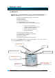
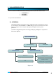
The next schema represents available pages to be "enabled" and its hierarchy. “Home” Page “MENU” Page Specific Pages Access ‐ SCENES 1 ‐ SCH. PROGRAMMING ‐ CLIMA “Home II” Page ‐ SCENES 2 ‐ SCH. PROGRAMMING ‐ CLIMA ‐ SCENES 3 ‐ SCH. PROGRAMMING ‐ CLIMA ‐ SCENES 3 ‐ SCH. PROGRAMMING ‐ CLIMA TECHNICAL CONFIGURATION 5 6 ALARMS Figure 1.1 MENU PAGE Back to Home Page ZENNiO AVANCE Y TECNOLOGÍA CONFIGURATION PAGE www.zennio.
Next sections in this manual, will detail the correct way to configure and program the LCD Panel InZennio Z38, so that a user can control all (or part of) the KNX installation from a single device. o <> ¾ Home & Home II The “Home” page is the InZennio Z38 “Welcome” page; this will be the starting point (once the necessary boxes have been enabled) to access, the most commonly required functions.
1.3. CONFIGURATION The INZennio Z38 includes 217 Communication Objects responsible to transmit and receive data through the BUS. To begin with the InZennio Z38 module configuration, it will be necessary to import in ETS, a project that contains an InZennio Module of the device, or a database .vd file of the product (See www. Zennio.com) This manual starts from the "default" product configuration, to gradually configure the device according to the user requirements.
o Main Parameterization Window appears ZENNiO AVANCE Y TECNOLOGÍA www.zennio.
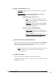
2. PARAMETERIZATION Access via ETS to the Main Parameterization Page on the ETS, has three main sections: <> <> <> Every section is detailed next: 2.1. GENERAL This parameterization section, allow users to enable the remote control zones as well as to associate them with the “Home” or “Home II” pages for its control; this section also allows to configure various aspects of the display backlight and other general parameters.
DISPLAY BRIGHTNESS (Figure 2.1) ¾ Always ON: Light on the display remains always ON, even when the page is not in use. ¾ Auto Dimming: 45 seconds after the last interaction on the display, this will recover its stand-by mode.
Time Zone Date‐ (M) Monday Note: Week days are automatically calculated by the own display when adjusting the date on it. REMOTE CONTROLLER ¾ Zone 1: This field will allow users to associate this zone of the control to either any of both “Home” or “Home II” pages. Zone 1 Zone 2 ¾ Zone 2: This field will allow users to associate this zone of the control to either any of both “Home” or “Home II” pages.
TEMPERATURE SENDING PERIOD This field is meant to set a period of time for the Z38 to send the registered temperature to the BUS through the “Temperature-Internal Sensor value” Communication object. 2.1.1. « DISPLAY BRIGHTNESS » OBJECT The Z38 Panel has a Communication Object “Display Brightness” which has the same effect than touching onto the display. ¾ When this object receives a “1” from the BUS, the display lights up and gets active.
Note: The “Home” page is enabled by default. Access to the “Home” page cannot be restricted. NAME 4 DIGITS PASSWORD CANCEL/DELETE RESET PASSWORD Resetting the paswword: 1º Push NEW Old: Enter old password 2º New: Enter new password 3º Repeat: Confirm new password 2.2.1. « HOME » & « HOME II » PAGES These two pages are intended to parameterize their boxes so that a user can easily access the most common used functions when controlling an installation.
Note: “Home” Page will be shown again 90 seconds after last interaction on the display took place. 2.2.1.1. BINARY CONTROL This is a generic control to communicate all those devices susceptible to be, by sending a single bit (0 / 1). BUTTON 1 Æ In “Binary Control”, this button will always appear as “enabled” by default. ¾ Short Press: Choose whether to send: Nothing/0/1 or Toggle to the BUS through its Communication Object.
TYPE Æ Select the control type to use: ¾ On/Off: This is the most basic control type; Turn On/Off; pretends to simulate a common switch action. ¾ On/Off + Simple Regulation (4 bits): Users can simulate a common switch action, turn On/Off (short press on the buttons), or a discreet regulation (long press on the buttons), where depending on the “dimming step” set, keeping the button pressed will reduce or increase the brightness on the controlled lamps.
• Indicator: This will inform users about the brightness percentage applied at any time. ICON Æ An icon can be associated to the page box. (See Annexe II). 2.2.1.3. SHUTTER CONTROL Specifically designed to control any type of shutters, blinds, sun blinds, or any other drive. Through its communication objects, users will be able to raise / lower shutters, and even knowing its exact position at any time.
• • • • • Fan Blinds Special Mode (Comfort) Special Mode (Night) Special Mode (Out) Note I: Depending on the selected option, a communication object associated to the specific box will appear in the ETS environment; the same object type corresponding the selected option. This characteristic allows users to control also external climate systems.
Short Press: Rise or lower one single point in the range with every short key press. Long Press: Rise or lower 10 points in the range with every long key press. Note: Please notice that Value 0 corresponds with 0% …………………………………. …………………………………. Value 255 corresponds with 100% ICON Æ A couple of icons can be associated to the corresponding display box. (See Annexe II). 2.2.1.6.
Note I: If C=0, the DPT valid range is [0….63], whereas if C=1, the DPT valid range is [128…..191] Activate Scene 1 Æ DPT=0 Note II: Activate Scene 2 Æ DPT=1 Activate Scene 64 Æ DPT=63 Learn Scene 1 Æ DPT=128 Learn Scene 2 Æ DPT=129 .. Learn Scene 64 Æ DPT=191 Therefore, a single Communication Object will be valid to Activate Scenes and /or learn them (depending on the C value).
¾ Example: Guess a user defines the “Scene Night” (programming the Panel with parameters and group addresses via ETS): 9 Turn all the lights Off. 9 Turn Off the Heating and the A/C Systems. 9 Activate the Alarm System.
CONTROL RANGE Æ Choose between 2 available options: ¾ Normal Æ [10ºC…..30ºC] ¾ Extended Æ [0ºC…..95ºC] ICON Æ A couple of icons can be associated to the screen box. (See Annexe II). Note: Do not confuse the generic temperature control with the Climate Control associated to the set temperature (See Section 2.2.1.4). The generic Temperature Control can not be linked with any of the Climate Specific Pages. 2.2.1.8. BINARY INDICATOR This control enables a binary status indicator on the display box.
2.2.1.10. FLOATING POINT INDICATOR Floating Point is a real number representation method that can be adapted to the order of magnitude of the value represented. In this particular case, enabling a box as “Floating Point indicator”, integrators can select the type of data represented on the display, choosing among: • Temperature (ºC) Æ Range [-273ºC….670,760ºC] • Wind Speed (m/s) Æ Range [0m/s….670,760m/s] • Humidity (%) Æ Range [0%….
This function consists on the cyclical sending of “0” & “1” while activated. A random semi-cycle duration is applied for the ON/OFF within the parameterized limits. Note: This simulation can be enabled / disabled through the display or through an object; and once activated; this will only be running during the parameterized time range. STARTING TIME / FINISH TIMEÆ This parameter adjusts the time for the daily simulation to start/stop running (once enabled the function).
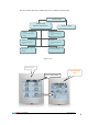
Button to: Button to: ‐ To move to the next item to change ‐ Increase time values ‐ Flag week days ‐ Change the type of response of the Channel: ON/OFF/BOTH The Schedule programming is associated to the On/Off of the devices in the KNX installation. Every time a user enables a specific “Schedule Programming” page; four free boxes with their respective Programming Channel Communication Objects will become available to be enabled if necessary.
carry out Schedule Programming associated to Clime and/or Scenes. PROG “ON” THERMOSTAT A/C Scenes On/OffÆ “1” ONÆ “Scene Nº” On/OffÆ “1” ComfortÆ “1” OFFÆ “N/A” OutÆ “1” Both Æ “Scene Nº” NightÆ “1” Figure 3.1 Note: We just mentioned that the schedule programming is associated with the On/Off of the installed devices. Figure 3.1 and Figure 3.2 show how the THERMOSTAT and the A/C systems are affected when a “1” or a “0” is sent through the corresponding channel.
2.2.2.3. CLIMA Air Conditioning, Thermostat and Fan Coil Control have been unified in a unique Specific Page called “Clima”. Thus, due to the possibility of enabling up to 4 different Climate Specific Pages, up to 4 different Climate Systems can be now controlled from the Z38. The number of “Specific Pages” to control Climate Systems will mainly depend on the number of different Systems to control in the installation.
- 2=Dry - 3=Fan - 4= Summer Note I: This second option can only be selected to control Air Conditioning Systems Note II: Enabling the Thermostat has no sense when this second Mode option has been selected, as the Thermostat can only control the Heat/Cool contribution.
BOX 5 (SPECIAL MODES) Æ This box is customizable as “Blinds” (for Air Conditioning control), or as “Special Modes – Comfort, Night, Stand-By” (for Thermostat).
THERMOSTAT Æ Select the type of control to carry out: • • • Only Heat Only Cool Heat & Cool REFERENCE TEMPERATURE Æ For every enabled thermostat in the Z38, users will be asked by parameter whether to use the internal sensor measure as a reference, or if on the other hand an external sensor will be used. The same parameterization field offers also the possibility to choose a proportion between both measures (Z38 internal sensor + external sensor).
¾ Protection Temperature: This parameter fixes the maximum temperature the user will accept. 9 Protection Temperature is measured in ºCelsius. 9 There is no connection between the “Set Temperature” and the “Protection Temperature”. 9 This is the real temperature to be applied as overheating protection. 9 Thermostat will turn Off when temperature in the room reaches “Protection Temperature – 1ºC” A small introduction to the Temperature Control methods used by the Z38 is detailed below.
PI CONTROL (Proportional-Integral Æ This control follows the Standard KNX rules. There are different systems to get a room conditioned: HEAT COOL -Warm Water -Floor Heating -Electric Heating -Blowi Convector - A/C Split -Cooling Ceiling -Blow Convector -A/C Split Depending on the climate control system used on the installation, the user must choose the suitable option. Any available option is internally parameterized for best performance in each case.
Note: The HEATING section has been parameterized following the “Hysteresis control method”, while the COOLING one has been parameterized following the “PI Control method”. However, both control methods can be used in either zone.
COOL CONTROL METHOD Æ To choose between “Hysteresis” or “PI Control” method ¾ Control Type: To choose between “PWM (1 bit)” and “Continuous (1 byte)” Control. ¾ Cycle Time: 9 PWM (1bit): This parameter it used to set a cycle period during which it’s calculating the pulse width modulation. 9 Continous (1 byte): This parameter set the cycle transmission of “control variable” Object. In this case, this variable is send after a value changing or periodically (time defined in this area).
Until now, when PWM or HYSTERESIS (1 bit control methods) were selected, there was no possibility to know whether the thermostat was in the “0” or in the “1” status. This makes users don’t know when the system is heating up and when is stopped. To display this status, a new LED (based on 4 pixels) has been added in the upper right side of the "ON" indicator in the first box of the Climate Page. This new LED will blink every second when the control variable is sending a “1”. 2.2.3.
Note: When an error or accident is detected on the KNX installation, InZennio Z38 will show the “Technical Alarms Screen”, and a danger icon will appear in the box affected; at the same time, the Panel blinks and emits a “beep” to warn the user. Once the warning reception is confirmed by the user (pressing the OK button), the screen will recover its normal state: After 90 seconds, Inzennio Z38 display will again show the “Home” default screen.
Note I: When a Power BUS failure occurs, please have on mind the delay this implies to correct it. Note II: There are different KNX devices on the market which can synchronize periodically the time and date of every single device in the installation. Such devices can be really useful when the installation is based on any kind of Schedule programming.
2.3. INPUTS The INZennio Z38 has 4 binary inputs for voltage-free contacts at the user’s disposal; these inputs can be individually configured, and connected to a “push button” if necessary. Joining an input with the global “common” of the inputs, results in a “Closed Contact”; the other option is an “Open Contact”. A push button connected to an input consists of a device, which allows, or not, the current flow while this is being pushed; in normal conditions, push buttons contacts are always “open”.
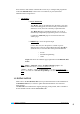
It is necessary to repeat this delimitation process of the touch zone every time a user makes a download to the screen via ETS. Available configuration options for the enabled “inputs” are detailed next: 2.3.1. SHORT PRESS Several configuration options are available for a “Short Press” on an Input: 2.3.1.1. ONE BIT SENDING “0/1” This function results on sending 1 bit to the BUS.
¾ Raise/Lower Switching: Alternative switching between the Pull Up/Down orders (to manage the shutter with an only input). ¾ Stop/Pull Up Step: Stops the shutter. When talking about shutters with lamellas, this mode allows the user to control them; this parameter moves lamellas a pull up step. The BUS receives a “0”. ¾ Stop/Pull Down Step: Stops the shutter; when talking about shutters with lamellas, this mode allows the user to control them; this parameter moves lamellas a pull down step.
¾ Increase Light: Every press on the screen increases the lighting level, this parameter depends on the “Dimming Step” set, (See below). A short press reduces the lighting level; a second press stops the “Increase”. ¾ Reduce Light: Reduces the lighting level with every press on the screen, this parameter depends on the “Dimming Step” set, (See below). A short press reduces the lighting level; a second press stops the “Reduction”.
2.3.2. LONG PRESS Configuration options are exactly the same as in the previous case “Short Press”. 2.3.3. THRESHOLD TIME This parameter defines the time limit where a short press turns into a long press. If a press on the screen ends before the long press time, then it is a short press. This value must be set with precision to tenths of a second (e.g. to get “0.5” seconds, set “5”) 2.3.4.
ANNEX I.
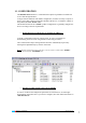
SPECIFIC X (CLIMA) SECTION 78 - 89 2bytes I WU 90 - 93 1bit O T 94 - 97 1bit O T O T 98 - 101 1bit O T 102 - 105 1bit O T 106 – 109 1byte O T 110 - 113 2byte O T 114 - 117 1bit I WU NUMBER SIZE IN/OUT FLAGS 99.9ºC99,9ºC 25ºC Previous [Home X Box X] Floating Point indicator [Clima X] On/Off control 0=Off; 1=On [Clima X] Fan Control 0=Auto; 1=Min; 2=Med; 3=Max.
Short Pr. -> Send.
ANNEX II.
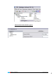
(35) – Up Arrow (51) – Plus (36) – Left Arrow (52) – Lower Temperature (37) – Right Arrow (53) – Raise Temperature AIR CONDITIONING (70) – Turn Off (82) – Stop Blades (71) – Turn On (83) – Move Blades (72) – Cool Mode (84) – Stop (73) – Heat Mode (86) – Auto (74) – Auto Mode (87) – Auto 2 (75) – Fan Mode (88) – Auto 3 (76) – Dry Mode (89) – Auto 4 (77) – Very Low Fan (78) – Low Fan (79) – Medium Fan (80) – High Fan (81) – Very High Fan NUMBERS (100) ‐ Zero (105) ‐ Five (101) ‐ on
(103) ‐ Three (108) ‐ Eight (104) ‐ Four (109) – Nine (110) – 0 (111) ‐ 1 SOUND & IMAGE (150) – Stop (159) – Lower Volume (151) – Play (160) – Raise Volume (152) – Rewind (161) ‐ Mute (153) – Forward (162) – Sound On (154) – Before (163) ‐ TV (155) – Next (164) ‐ Audio/Video (156) – Record (165) ‐ AUX (157) – Pause (166) ‐ Movie (158) – Eject (167) - Claqueta OTHER (200) ‐ Clock 1 (208) ‐ Comfort (201) ‐ Clock 2 (209) ‐ Night (202) ‐ Clock Off (210) ‐ Out (203) ‐ Clock On (2
(204) ‐ Clock Off 2 (212) – Very Strong (205) - Clock On 2 (218) – Key 2 (206) - Set (219) – New (207) - Ok ZENNiO AVANCE Y TECNOLOGÍA www.zennio.
ANNEX III. DOUBLE CONTROLS BINARY (1) – Turn On/Off (9) ‐ Turn On/Off Light 2 (3) ‐ Turn On/Off 2 (11) – Out/In (5) ‐ Turn On/Off 3 (13) – Cancel/Accept (7) - Turn On/Off Light (19) - Off / On (21) – Disarmed / Armed DIRECTIONAL & INCREMENTAL (30) – Down/Up (38) – Lower/Raise Shutter (32) – Left/Right (40) – Lower/Raise Shutter 2 (34) ‐ Down/Up Arrow (50) – Minus/Plus (36) – Left/Right Arrow (52) – Lower/Raise Temperature ZENNiO AVANCE Y TECNOLOGÍA www.zennio.
AIR CONDITIONING (70) ‐ Turn On/Off A/C (82) – Stop / Swing Blades (72) ‐ Cool / Heat (84) ‐ Stop / Swing Blades 2 (79) - Minus / More Fan NUMBERS (100) – Zero / One (106) – Six / Seven (102) – Two / Three (108) – Eight / Nine (104) – Four / Five (110) – 0 / 1 SOUND & IMAGE (150) – Stop / Play (159) – Minus / More Volume (152) – Rewind / Forward (161) – Sound Off / On (154) – Befote / Next (163) ‐ TV / AV ZENNiO AVANCE Y TECNOLOGÍA www.zennio.
OTHER (202) - Clock Off / On (211) - Strong / Stronger (204) ‐ Clock Off / On 2 (217) – Key 1 / Key 2 ZENNiO AVANCE Y TECNOLOGÍA www.zennio.
ANNEX IV. INDICATORS BINARY (1) – On (13) ‐ Rejected (2) ‐ Off (14) ‐ Ok (7) – Light Off (15) – Open Door (8) – Light On (16) – Closed Door (9) – Light Off 2 (17) – Open Window (10) – Light On 2 (18) – Closed Window (19) – Off (20) – On (21) – Disarmed (22) ‐ Armed DIRECTIONAL & INCREMENTAL (38) – Lowering Shutter (40) – Lowering Shutter 2 (39) – Raising Shutter (41) – Raising Shutter 2 ZENNiO AVANCE Y TECNOLOGÍA www.zennio.
AIR CONDITIONING (70) – A/C Off (82) – Stop Blades (71) ‐ A/C On (83) – Move Blades (72) – Cool Mode (84) – Stop (73) – Heat Mode (85) – Move Blades 2 (74) – Auto Mode (86) – Auto (75) – Fan Mode (87) – Auto 2 (76) – Dry Mode (88) – Auto 3 (77) – Very Low Fan (89) – Auto 4 (78) – Low Fan (79) – Medium Fan (80) – High Fan (81) – Very High Fan NUMBERS (100) – Zero (105) ‐ Five (101) – One (106) ‐ Six (102) – Two (107) ‐ Seven (103) – Three (108) ‐ Eight (104) – Four (109) ‐ Nine
SOUND & IMAGE (162) – Sound Off (163) – Sound On OTHER (200) ‐ Clock 1 (208) ‐ Comfort (201) ‐ Clock 2 (209) ‐ Night (202) ‐ Clock Off (210) ‐ Out (203) ‐ Clock On (211) ‐ Strong (204) ‐ Clock Off 2 (212) – Very Strong (205) ‐ Clock On 2 (213) ‐ Danger (206) – Set (214) – Danger Cold (207) – Ok (215) – Danger Hot (216) – Danger Wind (217) – Key 1 (218) – Key 2 (219) - New ZENNiO AVANCE Y TECNOLOGÍA www.zennio.
DOCUMENTATION TECHNICAL SIGN UP! http://zennioenglish.zendesk.com ZENNIO TECHNICAL SUPPORT ZENNiO AVANCE Y TECNOLOGÍA www.zennio.