
Operation Manual

ZENNiOAVANCEYTECNOLOGÍA www.zennio.com
34
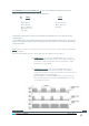
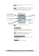
Until now, when PWM or HYSTERESIS (1 bit control methods) were selected, there was no
possibility to know whether the thermostat was in the “0” or in the “1” status.
This makes users don’t know when the system is heating up and when is stopped.
To display this status, a new LED (based on 4 pixels) has been added in the upper right side of
the "ON" indicator in the first box of the Climate Page.
This new LED will blink every second when the control variable is sending a “1”.
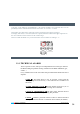
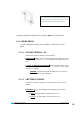
2.2.3. TECHNICAL ALARMS
This is a specific screen, with up to six independent boxes in charge to monitor
the BUS looking for possible warning conditions in the KNX installation (gas,
smoke...).
Every “Enabled” box on the screen has some parameterizable fields at the user’s
disposal:
NAME Æ
This field allows a user to associate a name with the
corresponding box in the screen, (11 free characters are available to set
the name).
ALARM TRIGGER VALUE Æ
Choose whether it will be a (“0” or
“1”); this will mainly depend on the warning device installed.
CYCLICAL MONITORING Æ
The state of the detection devices
will be cyclically monitored by enabling this parameter.
CYCLE Æ
Defines a particular interval of time to monitor the BUS
looking for Technical Alarms or a detection device failure (in minutes).