PRODUCT MANUAL ZAS KNX Room Controller ZN1VI-TPZAS Program version: 1.
INDEX 1. 2. 3. Introduction .............................................................................................................................................3 1.1. ZAS .................................................................................................................................................. 3 1.2. Installation ...................................................................................................................................... 4 Configuration .......
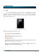
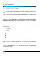
1. INTRODUCTION 1.1. ZAS The room controller ZAS (Zennio Analogue Screen) is a touch panel that includes thermostat, IR receiver, and analogue/binary inputs. ZAS is a great solution for demanding applications in hotel rooms, apartments, offices, and in any room where it is necessary to manage climate, shutters, lights, scenes, etc. Figure 1.1. ZAS Room Controller Below, the most relevant features of ZAS are shown: 1.
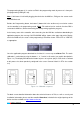
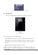
1.2. INSTALLATION ZAS is connected to the KNX installation as any other KNX device, through the KNX connector placed at the back. For installing ZAS, first it is necessary to fix the metallic piece into the squared/rounded standard box where it is going to be installed, with the corresponding screws. Next, the KNX bus and the inputs terminal must be connected using the corresponding connectors; both terminals are placed in the rear part of the device.
The programming button (3) is used to set ZAS in the programming mode, by means of a short push (the programming LED lights red). Note: If this button is held while plugging the device into de KNX bus, ZAS goes into secure mode. The LED blinks red. Besides the Programming button, the button 7 (bottom left in the tactile area) can also be used to set the controller in the programming mode.
2. CONFIGURATION 2.1. GENERAL CONFIGURATION ZAS allows controlling a set of functionalities in a domotic installation in a simple and intuitive way. There are several parameters that reference to the general functioning of the controller, such as: luminosity, touch blocking, initial setup, internal sensor, contrast, screensaver, information screen, Menu screen enabling, etc. ZAS counts on 2 opto-coupled inputs that may be individually configured as switch/sensor or temperature probe.
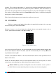
Figure 2.1. Menu representation example in the Display 2.2. TACTILE AREA ZAS counts on 12 tactile buttons for controlling all its functionalities. See figure 2.1. Tactile Area Figure 2.1. Tactile Area The first row of the touch consists of the following buttons: Button Menu: allows the direct access to the menu, which has also several sub-menus.
functions. They are direct-action buttons, i.e., they will carry out the parameterized action every time they are pressed, no matter the manu or submenu the panel is. Moreover, when these buttons are pressed, the text message previously configured in ETS for every action will appear in the display (see section 3.4). Each button counts on a central LED that lights during 1 second for showing that the key-press has been correctly done.
Buttons F1 and F2: they allow sending 1-bit object configurable from ETS for sending a “0”, a “1” or switching between “0” and “1”. Buttons Comfort, Night and Standby: they allow directly establishing the special thermostat modes Comfort, Night and Standby. It is necessary that these modes had been previously enabled in ETS (thermostat). Button Switch off: a short press switches off the ZAS display.
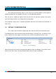
3. ETS PARAMETERIZATION For starting to parameterize ZAS it is necessary, once the ETS program has been opened, importing the data base of the product (Version 1.2 of the application program). Next, the device is added to the project where desired. Click the right mouse button on the device and select "Edit parameters" for starting with the configuration. In the following sections there is a detailed explanation about each of the different functionalities of ZAS in ETS. 3.1.
Figure 3.2. Configuration screen by default 3.2. GENERAL The parameterization window General allows configuring the basic functionalities, menus and screens of the room controller ZAS. The basic functions that can be configured in the section General are the following: General labels: to insert the text chains that will identify the common options to several functions, as: OFF, ON, SCENE, SAVED SCENE, and the text chains to guide the user through the calibration process. Luminosity.
It is also possible to configure two special levels of luminosity than can be activated through 1-bit communication objects ("[General] Display lighting 1 and 2") or through scenes (via the specific object for scenes). Moreover, it can be configured the desired luminosity level for each special level (from 1 to 10). Figure 3.3. Luminosity function Touch blocking. This function allows blocking and unblocking the ZAS buttons.
Figure 3.4. Touch blocking Initial updating This functionality allows re-establishing the value of the general indicators (if enabled by parameter) as well as the values of the 1-bit objects associated to the buttons, after a power failure. Moreover, this functionality allows establishing a delay for sending the initial values since the power is recovered. Note: If this function is not enabled, the values prior to the bus power failure will be kept. Remote control.
Internal Temp. Sensor. ZAS has an internal temperature sensor with an associated 2byte communication object ("[General] Temperature"), which appears when the the internal sensor function is enabled in the General parameterization screen. In the box "Internal Temp.
General indicators: enables a new screen with the same name, to configure up to 6 general indicators, of different types: Binary (1 bit): it shows different texts according to the received value. Counter (1 byte) Percentage (1 byte) Enumeration (1 byte): it allows the introduction of up to 6 numerical values with their corresponding labels (configurable texts by parameter). Float (2 bytes): it shows the received value specifying the units (configurable text by parameter).
Menu: In the section Menu, the different options of ZAS can be enabled. When each of these options is enabled, it could be configured selecting the corresponding section in the lateral menu of the parameters edition. Each of them will be explained in detail in section 3.2.1. Menu options. In the field Header it is possible to write an identificative name for the Menu. Information screen: it shows an image of the touch buttons (see figure 3.
Figure 3.9. Menu configuration, by default Next, the menu dunctionalities are explained in detail. Thermostat ZAS has the option to enable the thermostat for the following regulation types: Heating, Cooling or Heating and Cooling. The default main thermostat screen in the one showed in Figure 3.10. Figure 3.10. Thermostat Configuration Once chosen the regulation type (or mode), a new access is enabled in the left menu: Thermostat Function: Heating.
Freezing protection: Allows acting over the thermostat automatically if the temperature measured reaches a minimum temperature value defined in the "Protection Temperature" parameter (ºC). The system is able to react instantaneously to face this situation, maintaining the temperature always above this fixed value. This protection only has effect with the thermostat switched off.
"Protection Temperature" parameter (ºC). The system is able to react instantaneously to face this situation, maintaining the temperature always below this fixed value. This protection only has effect with the thermostat switched off. Control method: the same as for "Heating".· Additional cooling: enabling this field, the auxiliary system is asked to contribute to reach the “Set temperature” as soon as possible. The additional cooling band (in tenths of degree) must be configured.
Scenes. ZAS allows configuring up to 6 different scenes for running or running and saving. Figure 3.11. Scenes All the scenes allow the configuration of a name and the value associated to the scene (scene number, between 1 and 64). Presence simulation: this function has two windows associated: one for its configuration and the other, for defining the labels of the functionality. Figure 3.12.
The presence simulation allows introducing the Starting time, Final time and the maximum and minimum ON and OFF times for the presence simulation. Note: The value established for Maximum Time (both ON and OFF) must be greater than the value established for Minimum Time, in order not to generate a wrong parameterization that may cause anomalous situations.
Figure 3.14. Configuration 3.3. INPUTS ZAS has two inputs that can be configured as switching/sensor or temperature sensor. Once the input is enabled, the access to the corresponding configuration window appears in the main menu according to the configured type of input. 3.3.1. SWITCH/SENSOR When configuring an input as switching/sensor, it is necessary to select the action to carry out in the falling edge and the rising edge: Figure 3.15.
The available options are: Rising edge: select the sending value when this edge happens: Nothing (no action is performed). 0: the object "[Ix][Sensor] Edge" is sent to the KNX bus with value "0". 1: the object "[Ix][Sensor] Edge" is sent to the KNX bus with value "1". Switching: sending "0" or "1" to the KNX bus, as appropriate. Falling edge: select the sending value when this edge happens: Nothing, 0, 1 or switching.
3.3.2. TEMPERATURE PROBE When configuring an input as a temperature probe, the following options can be configured: Figure 3.16. Input: Temperature probe Temperature sensor calibration: to re-calibrate (setting the tenths of degree) the sensor to take as reference any other sensor present in the installation, thus synchronizing the measurement of the two. Temperature sending period: to select by parameter the time (in tens of second) to send cyclically to the KNX bus the current temperature measurement.
3.4. BUTTONS ZAS has 8 buttons, which can be configured individually or in couple, through the specific window "Buttons". Besides deciding whether the arrow buttons will be used or not. Figure 3.17. Buttons configuration The "Pair buttons configuration" parameter sets whether the right button is used for On/Increment value sending and the left button is used for Off/Decrement value sending, or the opposite.
3.4.1. INDIVIDUAL BUTTONS The configuration options for the individual operation of the buttons are the following: 1 bit: it allows sending the value “0”, “1”, or toggle between them. There is an associated 1-bit communication object called "[Bx] Binary control" The LED of the button will light when a "1" is sent and it will be off when sending a "0". If the Toggle option is selected, the parameter "LED lighting" will appear.
3.4.2. COUPLE BUTTONS The configuration options for the couple operation of the buttons are the following: Switch: enables a 1-bit communication object "[Bxy] Binary control" for each couple, which will be set to value "0" or "1", depending on the button that was pressed. This option allows introducing the name of the functionality, associated to the buttons, and a text message for the actions Switch On and Switch Off.
Dimming step Necessary pulsations for a complete regulation (0-100%) (1). 100% (2). 50% (3). 25% (4). 12.5% (5). 6.25% (6). 3.1% (7). 1.5% 1 2 4 8 16 32 64 Table 3.1. Dimming step Shutter: it allows controlling the movement of shutters by means of two binary objects: "[Bxy] Move shutter" ("0"=Up and "1"=Down) and "[Bxy] Stop shutter" and 1-byte object "[Bxy] Shutter position", which indicates the position of the shutter, in percentage, at any time (100%=Down, 0%=Up).
Enumeration: allows sending a numerical value (0-255) via the object "[Bxy] Enumeration" associated to the couple of buttons. Up to 6 values can be configured for the enumeration (Value 1-Value 6). It is necessary to introduce a label for each value in order to enable them in the enumeration menu. When pressing the right and left button, the different labels will be shown in the display and their value sent to the bus. First press will show the current value of the control.
ANNEX I.
SECTION INDICADORES BUTTONS NUMBER SIZE IN/OUT VALUES FLAGS NAME RANGE 1st TIME RESET DESCRIPTION 13 1 bit I TWU 0/1 0 Last [Ind 5] Binary indicator 1-bit generic indicator 14 1 bit I TWU 0/1 0 Last [Ind 6] Binary indicator 1-bit generic indicator 15 1 byte I TWU 0-255 0 Last [Ind 1] 1 byte indicator 1 byte generic indicator 16 1 byte I TWU 0-255 0 Last [Ind 2] 1 byte indicator 1 byte generic indicator 17 1 byte I TWU 0-255 0 Last [Ind 3] 1 byte indica
SECTION NUMBER 31-34 35-38 BUTTONS INPUTS PRESENCE SIMULATION SIZE 4 bits 1 byte IN/OUT O O VALUES FLAGS TR TR NAME RANGE 1st TIME RESET 0-15 0 Last 0-255; 0-100% 0 Last 39-42 2 bytes I/O TRW 0-100ºC 25ºC Last 43-46 1 bit O TR 0/1 Indifferent Indifferent 47 2 bytes I/O TRW 0-100ºC 25ºC Last 48-55 1 bit I/O TRW 0/1 0 Last 56-63 1 bit O TR 0/1 0 101-108 1 byte O TR 0-255 109-116 2 bytes O TR 0-65535 0-120.
SECTION PRESENCE SIMULATION MENU NUMBER SIZE IN/OUT VALUES FLAGS NAME RANGE 1st TIME RESET 69 1 bit O TR 0/1 0 Last 76 1 bit I TW 0/1 0 Indifferent 77 1 bit O TR 0/1 0 78 2 bytes I TW 0-95ºC 79 2 bytes O TR 80 1 bit I 81 1 bit O 82 1 bit O Simulation channel DESCRIPTION 0=Off; 1=On Thermostat - ON/OFF 0=Off; 1=On Last Thermostat - ON/OFF Status 0=Off; 1=On 25ºC Last Setpoint Temperature from 0ºC to 95ºC 0-95ºC 25ºC Last Setpoint status from 0º
SECTION MENU NUMBER SIZE IN/OUT NAME RANGE 1st TIME RESET DESCRIPTION 91 2 bytes I W 0-95ºC 23ºC Last Comfort setpoint (heat) Temperature for comfort mode 92 2 bytes I W 0-95ºC 28ºC Last Night setpoint (cool) Temperature for night mode 93 2 bytes I W 0-95ºC 21ºC Last Night setpoint (heat) Temperature for night mode 94 2 bytes I W 0-95ºC 30ºC Last Standby setpoint (cool) Temperature for standby mode 95 2 bytes I W 0-95ºC 19ºC Last Standby setpoint (heat)
DOCUMENTATION TECHNICAL SUPPORT TECHNICAL http://zennioenglish.zendesk.