848ER893A0 (804) OWNER'S MANUAL Model: G240RC/G270RC Model code: X374323111 (G240RC) Model code: X374326111 (G270RC) Thank you for using ZENOAH ENGINE. ● Please read this Owner’s Manual thoroughly before operating and use the engine correctly according to this Owner’s Manual. (For safety reasons, please contact your sales dealer before operating this engine if there is something that you do not understand.) ● This engine has been designed for the use of radio control car.
CONTENTS SPECIFICATIONS.....................................................4 SAFETY PRECAUTIONS..........................................5 FUEL .........................................................................7 ENGINE STARTING..................................................8 OPERATION .............................................................9 MAINTENANCE ......................................................10 SPECIAL TOOLS ....................................................
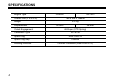
SPECIFICATIONS Engine Type G240RC Overall Size (L x W x H) Weight Displacement Clutch Engagement Carburetor Type Spark Plug Spark Plug Gap Rotating Direction 4 G270RC 166 x 205 x 196mm 2.07kg 22.5cm3 25.4cm3 6000rpm (STD Spring) WT-813A NGK CMR7H 0.
SAFETY PRECAUTIONS ● These safety precautions are to prevent you and those people in the vicinity from incurring harm or damage. Make sure to observe these precautions and constantly strive to ensure safety. ● Safe use of the engine is your personal obligation and responsibility. Constantly take care to act with good judgment as you enjoy your hobbies. • The fuel is toxic. Do not let it get into your eyes or mouth. Store it in a cool place, out of the reach of infants and children.
SAFETY PRECAUTIONS overly long sleeves, neckties and the like. Failure to do so could result in injury. • When mounting the engine to a model, make sure to follow the model’s operating manual. If necessary, reinforce the engine mounting unit and the peripheral parts.
FUEL • Mix gasoline (octane over 95) and high grade 2 cycle engine oil (mixing use type; F3C grade or ISO EGC grade) at mixing ratio 25~40:1. • The mixing ratio is according to the oil recommendation. [ NOTE ] 1) Never use any alcohol fuel or alcohol added fuel, or the rubber parts in the carburetor and engine will be damaged. 2) Gasoline is very flammable. Avoid smoking and any fires near fuel.
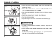
ENGINE STARTING Primer Pump Fig.1 Choke Lever Close Open Fig.2 • Push the primer pump several times until overflown fuel flows out. (Fig.1) • Close the choke lever, and move the throttle lever 1/4~1/3 open position. (Fig.1)(Fig.2) • Pull the starter(knob) quickly until first firing noise. (Fig.3) • Open the choke(Fig.2), throttle idle~1/4 open • Pull the starter quickly • Operate engine for a few minutes for the warming up. IMPORTANT Throttle Lever Fig.
OPERATION • This engine is already tuned up to get high power and high speed, and needs correct maintenance to keep such high performance. • The details for operation may be described in the separate owners manual to be issued by car manufacturer. • Be sure to have the engine cool down for 30 seconds at idle speed after full throttle running.
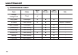
MAINTENANCE 1) MAINTENANCE CHART 10 Items Action Before Use Leakage, Damage/Crack Check ✔ Idling Speed Check/Adjust ✔ ✔ Every 25 hours Every 100 hours ✔ ✔ ✔ Note Air-cleaner Check/Cleaning Spark Plug(gap) Check/Adjust ✔ ✔ ↑ Cylinder(barrel) Check/Cleaning ✔ ✔ ↑ Piston, Ring Check/Cleaning ✔ ✔ ↑ ✔ ✔ ↑ ✔ ✔ ↑ ✔ ↑ Muffler & Bolt Check/Cleaning Bearings Check/Cleaning Crank Shaft Check/Alignment ✔ Replace if necessary
MAINTENANCE 2) SPECIFICATIONS AND TECHNICAL DATA Items Unit G240RC G270RC Bore x Stroke mm 32 x 28 34 x 28 Displacement cm3 22.5 25.4 8.9 8.9 Effective Compression Ratio Carburetor Type Walbro WT ← Venture(mm) ø12.7 ← Recoil Starter ← Type TCI ← Timing BTC 30°/8000rpm ← Standard CMR7H ← NGK CR8HIX with Terminal Nut CMR6H 6000 19500 4000 1.77/12000 1.56/9000 616 1 1/8 ± 1/4 1 1/4 ± 1/4 ← ↑ ← ← ← ← 1.80/12000 1.
MAINTENANCE 3) MAINTENANCE SPECIFICATIONS Cylinder Items Bore (mm) Diameter (mm) Piston Piston Ring G270RC Standard Limit Measuring Device ø34 Plating damaged Eye Checking ø31.97 ø31.87 ø33.97 ø33.87 Micro Meter 0.81 0.91 1.01 1.11 Thickness Gauge Piston Ring Groove width (mm) Piston Pin Hole (mm) Clearance between Piston and Cylinder (mm) Clearance between Groove and Piston Ring (mm) ø8.01 ø8.05 ø8.01 ø8.05 Cylinder Gauge 0.03~0.06 0.15 0.03~0.06 0.
MAINTENANCE 4) CARBURETOR Items Standard Limit ± 0.16 Measuring Device Metering Lever set (mm) 1.65 Inlet Valve Opening Pressure (kg/cm2) 1.3~2.3 Leak Tester Inlet Valve Closing Pressure (kg/cm2) 0.7~1.7 Leak Tester Remarks Vanier 5) IGNITION SYSTEM Items Standard Limit Measuring Device Spark Plug Air Gap (mm) 0.6~0.7 0.7 Thickness Gauge Ignition Coil/Flywheel Air Gap (mm) 0.3 0.4 Thickness Gauge Primary 0.7 — Volt Meter Reading between primary terminal and iron core.
MAINTENANCE 6) TIGHTENING TORQUE 14 Items Screw Size Standard (N·m) Limit (N·m) Carburetor M5 (P=0.8) 3.4 2.9~3.9 Insulator M5 (P=0.8) 4.4 3.9~4.9 Clutch M6 (P=1.0) 6.4 4.9~7.8 Rotor M8 (P=1.0) 12.7 9.8~14.7 Cylinder M5 (P=0.8) 6.8 4.7~8.8 Crankcase M5 (P=0.8) 6.4 4.9~7.8 Spark Plug M10 (P=1.0) 10.8 8.8~12.8 Muffler M5 (P=0.8) 8.8 6.9~9.8 Fan Cover M5 (P=0.8) 3.4 2.9~3.9 Ignition Coil M4 (P=0.7) 3.2 2.5~3.9 Starter Case M4 (P=0.7) 1.3 1.0~1.
SPECIAL TOOLS Part Name Part No. External Appearance Usage 1 Puller Assy 2890-96100 To remove rotor. 2 Piston Stopper 4810-96220 To hold crankshaft when disassembling/assembling clutch and rotor. 3 Rod Assy 1101-96220 To remove/install piston pin. 4 Air Gap Gauge 3330-97310 To set ignition coil. 5 Hex Wrench 3304-97611 For socket screw of Hex. 3mm, 4mm and 5mm. 6 Snap Ring Pliers 5500-96110 To remove snap ring.
SERVICE GUIDE Clutch Bolt (14mm Hex.) Rotor Nut Puller Bolts 17mm Hex. Puller Rotor 16 1) REMOVING CLUTCH SHOE 1. Remove the housing and plug cap. 2. Remove the spark plug and fit the stopper(481096220) into the plug hole. 3. Remove clutch bolts(14mm Hex.). 2) REMOVING ROTOR (FAN) 4. Remove the rotor nut(12mm Hex.). 5. Remove the rotor using the puller assy (2890-96100). Apply 8mm puller bolts.
SERVICE GUIDE 3) ASSEMBLING ROTOR Insert the gauge(3330-97310) in between the rotor magnet metal and the coil.Tighten screws while pressing the coil against the rotor. Ignition Coil Wrench Air Gap 0.3 ~ 0.4mm Air Gap Gauge Rod Assy Piston Plastic Hammer 4) REMOVING PISTON PIN 1. Remove snap rings from both sides of the piston pin. 2. Engage the rod assy(1101-96220) to the piston pin and gently tap with a plastic hammer to push out the pin while holding piston firmly.
SERVICE GUIDE End Gap Arrow Mark Piston Circlip 5) INSTALLING PISTON 1. Make sure to point the arrow mark on the piston to the exhaust side. 2. Fit the circlip in the groove so as to face the end gap below. NOTE Deformed circlip may come off during engine operation and damage the engine.
TROUBLE SHOOTING 1) ENGINE DOES NOT START Description Cause No spark in the spark plug Spark Plug 1. Wet spark plug electrodes 2. Carbon deposited on the electrodes 3. Insulation failure by insulator damage 4. Inproper spark gap 5. Burn out of electrodes Magneto 1. Ignition coil inside failure 2. Damaged cable sheath or disconnected cable Switch 1. Switch is OFF 2. Switch failure 3.Primary wiring earthed Sparks appear in the spark plug Compression & 1. Over sucking of fuel fueling is normal 2.
TROUBLE SHOOTING 2) LACK OF POWER OR UNSTABLE RUNNING Description Cause Countermeasure Compression is normal 1. Air penetration from fuel pipe joints, etc Secure connection and no misfire 2. Air penetration from intake tube joint or carburetor joint Change gasket or tightening screws 3. Water in fuel Change with good fuel 4. Piston start to seizure Replace piston(and cylinder) 5. Muffler choked with carbon Cleaning 1. Fuel too lean Adjust carburetor Overheating 2.
PARTS LIST 21
PARTS LIST G240RC (X374323111) 22
G240RC (X374323111) 23
PARTS LIST G240RC (X374323111) KEY# PART NUMBER 1 2 3 4 5 6 7 8 9 10 11 12 13 14 15 16 17 18 19 20 21 22 23 24 25 26 27 28 29 30 31 32 33 34 24 848ER812A0 T2075-13120 3310-12281 1148-13162 848ER814B0 T2075-14120 3310-12281 T2070-15110 01252-30550 1140-13141 1850-32160 848ER82110 2629-21130 5500-21141 1155-21240 2169-21210 06034-06001 04065-02812 01252-30530 T2071-41110 T2071-41210 1101-41310 1260-41320 5500-41410 1101-41340 T2070-42001 1650-43230 1000-43240 1140-43250 1140-51111 T2070-51220 1140-51250 11
G240RC (X374323111) KEY# PART NUMBER DESCRIPTION Q'TY/ REMARKS UNIT 69 70 71 72 73 74 75 76 77 78 79 80 81 82 83 84 1751-81510 2867-81270 3356-81310 1480-81420 3310-81230 3310-81240 3310-81250 2630-81330 3350-81380 848ETZ81T1 2670-81410 2880-81470 3310-81340 3310-81360 1790-81440 1148-81390 • PUMP • SPRING • VALVE inlet • PLUG welch • LEVER • SCREW • PIN • SCREW • SPRING • SHAFT throttle • SPRING • SCREW • VALVE throttle • SCREW • LEVER throttle • RING 1 1 1 1 1 1 1 1 1 1 1 2 1 1 1 1 86 87 88 89 90 9
PARTS LIST G270RC (X374326111) 26
G270RC (X374326111) 27
PARTS LIST G270RC (X374326111) KEY# PART NUMBER 1 2 3 4 5 6 7 8 9 10 11 12 13 14 15 16 17 18 19 20 21 22 23 24 25 26 27 28 29 30 31 32 33 34 28 848ET812A0 T2075-13120 3310-12281 1148-13162 848ER814B0 T2075-14120 3310-12281 T2070-15110 01252-30550 1140-13141 1850-32160 848ER82110 2629-21130 5500-21141 1155-21240 2169-21210 06034-06001 04065-02812 01252-30530 T2088-41110 T2088-41210 1600-41310 1260-41320 5500-41410 1101-41340 T2070-42001 1650-43230 1000-43240 1140-43250 1140-51111 T2070-51220 1140-51250 11
G270RC (X374326111) KEY# PART NUMBER DESCRIPTION Q'TY/ REMARKS UNIT 69 70 71 72 73 74 75 76 77 78 79 80 81 82 83 84 1751-81510 2867-81270 3356-81310 1480-81420 3310-81230 3310-81240 3310-81250 2630-81330 3350-81380 848ETZ81T1 2670-81410 2880-81470 3310-81340 3310-81360 1790-81440 1148-81390 • PUMP • SPRING • VALVE inlet • PLUG welch • LEVER • SCREW • PIN • SCREW • SPRING • SHAFT throttle • SPRING • SCREW • VALVE throttle • SCREW • LEVER throttle • RING 1 1 1 1 1 1 1 1 1 1 1 2 1 1 1 1 86 87 88 89 90 9
WARRANTY WARRANTY TERMS 1) Scope of Application This engine manufactured by Husqvarna Zenoah Co., Ltd. (herein after “Zenoah”). And sold to the user directly or through distributor/manufacturer, shall entitle to be covered by this warranty. 2) Limits of Warranty Zenoah warrants that; 1. The quality disclosed in the specifications. 2. The engine which shall be considered defective by Zenoah, caused by material or production fault. 3) Limits of Compensation 1.
WARRANTY 4) Term of Warranty Three (3) months after purchased by end- user subject to 12 months from produced month. 5) Exempt from Warranty Zenoah shall not warrant this engine even if the fault has been caused during the period of terms of Warranty, in case that. 1. Any faults, failures caused from neglect of proper operation and maintenance described in OWNER’S MANUAL. 2. Any modification not approved by Zenoah. 3. Normal abrasion and deterioration. 4. Consuming parts. 5.
Head Office : 1-9 Minamidai, Kawagoe-city, Saitama, 350-1165 Japan Phone: (+81)49-243-1115 Fax: (+81)49-243-7197