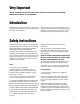
® ENGINE INSTRUCTION MANUAL 4 3 5 2 7 1 6 G26 Air G26/G231 Marine G26/G231 Heli G38 G62 GT80 Twin G45 1 2 3 4 5 6 7
Table of Contents Introduction . . . . . . . . . . . . . . . . . . . . . . . . . . . . . . . . . . . . . . . . . . . . . . . . . . . . . . . . . . . . . . . . . . . . . . . 3 Safety Instructions . . . . . . . . . . . . . . . . . . . . . . . . . . . . . . . . . . . . . . . . . . . . . . . . . . . . . . . . . . . . . . . . . . 3 Support Equipment . . . . . . . . . . .
Very Important Failure to read and follow these instructions before you proceed may result in engine damage and the voiding of your warranty! Introduction Congratulations on purchasing a Zenoah® engine. Cared for properly, these high-quality, finely crafted engines will offer many years of reliability. This instruction manual has been developed to ensure optimum performance from the Zenoah engine you have purchased.
Safety Instructions (continued) Caution Disassembly 1. Model engines get very hot while running. Do not attempt to handle them until they have cooled. The Zenoah engine can be disassembled or reassembled without any specific difficulties. Refer to the Engine Maintenance Section for specific instructions on these procedures. If you need service to your Zenoah engine, please send it to the authorized service center at the . following address: 2. Always run your model engines in a well-ventilated area.
Mounting the Engine Make sure the engine is mounted on the aircraft using aircraft grade plywood that’s at least 6mm in thickness for the G26 engine, and 10mm in thickness for the G38 through GT80 twin, or a mount of equivalent strength. Make sure it’s firmly mounted with 4 bolts. 1. Be sure to set flat washers or a metal plate on the reverse side of the mount to prevent the bolts from sinking into the mount. Periodically check the engine mount for loose bolts. 2.
Operation (continued) 8. Quickly flip the propeller in a counterclockwise direction. (See note on previous page) We recommend the Zenoah ZEN20000 Kill Switch. Refer to the example shown in the following diagram. 9. The engine should start after a few flips of the propeller. 10. Be sure to open the choke when the initial firing of the engine is heard. Red Lead 11.
Operation (continued) High-Speed Needle: Turning this needle clockwise makes the gas mixture leaner, and turning it counterclockwise makes it richer. Set this needle at a position which is 1/4 open from the maximum rpm position while the aircraft is on the ground. When the engine has just started and is not warm enough, there may be insufficient acceleration and the engine may die. Be sure to allow the engine to warm up at idle for a few minutes before conducting normal operation.
Engine Care and Maintenance (continued) c. Remove the rotor by using the puller. Do not hit the crankshaft with the plastic hammer, as this can increase the runout of the shaft. 7. Remove the mounting plate. 8. Remove the four bolts from the crankcase. 9. Tap around the case fitting side gently with the plastic hammer and slowly separate the crankcase from the cylinder block. 10. Pull out the crankshaft with the piston, bearings, and other parts attached. 8.
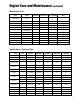
Engine Care and Maintenance (continued) Maintenance Chart Items Action Before Use Every 25 hours Every 100 hours Leakage, Damage/Crack Check Losing Speed Check/Adjust Air-cleaner (PUH) Check/Cleaning Spark Plug (gap) Check/Adjust Cylinder (barrel) Check/Cleaning Piston, Ring Check/Cleaning Muffler & Bolt Check/Cleaning Bearings Check/Cleaning Crankshaft Check/Alignment Rotor Check Propeller Hub (PU) Check/Alignment Water Jacket (PUM) Check/Leakage P P P P P P P P P P P P P P P P
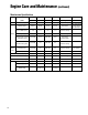
Engine Care and Maintenance (continued) Maintenance Specifications Items Standard Limit Standard Limit Measuring Device Bore (mm) ø34 Plating damaged ø32 Plating damaged Eye Checking Diameter (mm) ø33.97 ø33.87 ø31.97 ø31.87 Micro Meter Piston Ring Groove Width (mm) 1.01 1.11 1.01 1.11 Thickness Gauge Piston Ring Hole (mm) ø8.01 ø8.05 ø8.01 ø8.05 Cylinder Gauge Clearance Between Piston and Cylinder (mm) 0.03–0.05 0.15 0.03–0.05 0.
Troubleshooting Guide for Gasoline Engines Generally speaking, there are very few things that will keep today’s modern engines from starting. Use good quality “fresh” fuel and make sure that good plugs are installed. Should the engine fail to start after these items are verified, refer to the charts on the following page. a) The engine does not start.
Troubleshooting Guide for Gasoline Engines (continued) In the event that none of the above procedures result . in the engine running properly, contact our service department for suggestions at: Horizon Hobby, Inc. 4105 Fieldstone Road Champaign, IL 61822 Phone: 217-355-9511 (M–F 8:00–5:00 CST) Propeller Chart This chart enables you to select the best propeller for initial setup of your Zenoah engine. Remember, it’s imperative to balance each propeller prior to installation onto your Zenoah engine.
Engine Specifications Outside Dimensions (mm) Items Length Width Height Operating RPM Optional Mufflers G26A 139mm 105mm 181mm 2,000–10,000 BIS07123 G26M 139mm 105mm 181mm 2,000–10,000 G26H 139mm 105mm 181mm 2,000–10,000 — — G231 HELI 142mm 105mm 181mm 3,000–11,000 G231 MARINE 142mm 105mm 181mm 3,500–15,000 G38 — — 170mm 130mm 215mm 2,000–9,000 BIS07138 G45 152mm 130mm 185mm 2,000–10,000 BIS07145 G62 162.5mm 140mm 185mm 2,000–10,000 BIS07163 GT80 191.
Exploded Illustration G26/G231 14 New Zen Key # Part # 1-1 1- 2 2-1 2-2 3 4 5 6 7 8 9 10 11 12 14 13 14 15 16 17 18 19 20 21 Out of Date Part # ZENT207512110 ZEN2601 ZENT207012111 ZEN2301RCA ZENT207612110 ZEN2601M ZENT207812110 ZEN23102M ZENT207612210 ZEN2603M ZEN0785100515 ZEN2304M ZEN0700013040 ZEN23105M ZENT207612320 ZEN23106M ZEN116012330 ZEN2307M ZENT207513120 ZEN23108 ZEN331012281 ZEN2309 ZENT207513150 ZEN2305RC ZEN114813162 ZEN23111 ZENT207514120 ZEN23112 ZENT207521100 ZEN23114 ZEN262921130
Exploded Illustration G26/G231 continued Quantity Per Unit New Zen Out of Date G260 G260 G260 G231 G231 Key # Part # Part # Description PU PUM PUH PUM PUH ZEN2322 ZEN0125230530 ZENT208841110 ZEN2623 ZENT207041110 ZEN2320RC ZENT208841210 ZEN2624 ZENT207041210 ZEN2321RC ZEN2625 ZEN160041310 ZEN2322RC ZEN110141310 ZEN2323RC ZEN126041320 ZEN550041410 ZEN2324RC ZEN110141340 ZEN2325RC ZEN23129 ZENT207542000 ZEN2330 ZEN115574110 ZEN2331 ZEN026210516 ZEN2327RC ZEN165043230 ZEN116075210 ZEN2333M ZEN2634 Z
Exploded Illustration (Standard Accessory for G380PU) G38 Index No. 1 2 3 4 5 6 11 12 13 14 15 16 17 18 19 20 21 22 23 24 25 26 27 28 29 30 31 32 33 34 35 16 New ZEN Part No.
Exploded Illustration G45 Index No. 1 2 3 4 5 6 7 8 9 10 11 13 14 15 16 17 18 19 20 21 22 23 24 25 26 27 28 29 30 31 32 New Part No.
Exploded Illustration G62 * (Accessory for G620PU-1) Index No. 1 2 3 4 5 6 7 8 9 10 11,12 13 14 15 16 17 18 19 20 21 22 23 24 25 26 27 28 29 30 New ZEN Part No.
Exploded Illustration GT80 Index No. Index No. 1 2 3 4 5 6 7 8 9 10 11 12 13 14 15 16 17 18 19 20 21 22 23 24 25 26 27 28 29 30 31 New ZEN Part No.
Warranty Information Warranty Repairs Exclusive Warranty- Horizon Hobby, Inc., (Horizon) warranties that the Products purchased (the "Product") will be free from defects in materials and workmanship for a period of 3 years from the date of purchase by the Purchaser. you must contact Horizon directly. This will enable Horizon to better answer your questions and service you in the event that you may need any assistance. For questions or assistance, please direct your email to . productsupport@horizonhobby.
Warranty Information (continued) Registration Form Fill in and mail this form along with your dated sales receipt (send a copy, keep the original for your files) within 10 days of purchase to: Horizon Service Center Attn: Zenoah Warranty Dept.
© Copyright 2007, Horizon Hobby, Inc. www.horizonhobby.com ZZPZ200 6135.