WWW.ZEPHYRONLINE.COM Tempest I AK7000CS, AK7036CS, AK7042CS, AK7048CS EN Use, Care, and Installation Guide FR Guide d’utilisation, d’entretien et d’installation C TM Airflow Control Technology SEP20.
PRO TEMPEST I UNDER-CABINET 2 Tempest I Use, Care, and Installation Guide
Contents ZEPHYRONLINE.COM Page Safety Information ............................................................................ 4-9 Types of Safety Warnings ................................................................... 4 General Safety ..................................................................................5-8 Operation ........................................................................................... 8 Electrical Requirements ........................................................
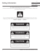
PRO Safety Information TEMPEST I UNDER-CABINET Your safety and the safety of others are very important. We have provided many important safety messages in this manual for your appliance. Always read and obey all safety messages. This is the Safety Alert Symbol. This symbol alerts you to potential hazards that can cause severe bodily injury or death.
Safety Information ZEPHYRONLINE.COM READ AND SAVE THESE INSTRUCTIONS General Safety WARNING To reduce the risk of fire or electric shock, do not use this fan with any solid-state control device. WARNING WARNING - TO REDUCE THE RISK OF FIRE, ELECTRIC SHOCK, OR INJURY TO PERSONS, OBSERVE THE FOLLOWING: a) Use this unit only in the manner intended by the manufacturer. If you have questions, contact the manufacturer.
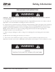
PRO Safety Information TEMPEST I UNDER-CABINET READ AND SAVE THESE INSTRUCTIONS WARNING WARNING - TO REDUCE THE RISK OF A RANGE TOP GREASE FIRE: a) Never leave surface units unattended at high settings. Boilovers cause smoking and greasy spillovers that may ignite. Heat oils slowly on low or medium settings. b) Always turn hood ON when cooking at high heat or when flambeing food. (i.e. Crepes Suzette, Cherries Jubilee, Peppercorn Beef Flambe’). c) Clean ventilating fans frequently.
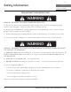
Safety Information ZEPHYRONLINE.COM READ AND SAVE THESE INSTRUCTIONS WARNING WARNING - TO REDUCE THE RISK OF FIRE, ELECTRIC SHOCK, OR INJURY TO PERSONS, OBSERVE THE FOLLOWING: a) Installation work and electrical wiring must be done by qualified person(s) in accordance with all applicable codes and standards, including fire-rated construction. b) Sufficient air is needed for proper combustion and exhausting of gases through the flue (chimney) of fuel burning equipment to prevent back drafting.
PRO Safety Information TEMPEST I UNDER-CABINET READ AND SAVE THESE INSTRUCTIONS CAUTION Ź To reduce risk of fire and to properly exhaust air outside, do not vent exhaust air into spaces within walls, ceilings, attics, crawl spaces, or garages. Operation Ź Always leave safety grilles and filters in place. Without these components, operating blowers could catch onto hair, fingers and loose clothing.
Safety Information ZEPHYRONLINE.COM READ AND SAVE THESE INSTRUCTIONS Ź This appliance requires a 120V 60Hz electrical supply and connected to an individual properly grounded branch circuit protected by a 15 or 20 ampere circuit breaker or time delay fuse. Wiring must be 2 wire with ground. Please also refer to Electrical Diagram on product. Ź A cable locking connector (not supplied) might also be required by local codes.
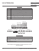
PRO List of Materials TEMPEST I UNDER-CABINET Parts Supplied Quantity 1 2 3 2 1 1 1 1 1 Part Hood Baffle filters Baffle filters (AK7048CS only) LumiLight LED, 6W (pre-installed) Single internal blower and blower plate (pre-installed) 8” round starting collar Rectangular starting collar (for single horizontal ducting) Rectangular metal cap (for single horizontal ducting) Hardware package #6 x 2” (4) #6 x 1-1/2” (4) #6 x 1” (4) M3.
Installation Instructions ZEPHYRONLINE.COM Ducting Calculation Sheet Equivalent number length x used = Duct pieces 1 Ft. x( ) = Ft. 6”, 7”, 8”, 10” 1 Ft. Round, straight x( ) = Ft. 3-1/ 4” x 10” Rect. 900 elbow 15 Ft. x( ) = Ft. 3-1/ 4” x 10” Rect. 450 elbow 9 Ft. x( ) = 3-1/ 4” x 10” Rect., straight 3-1/ 4” x 10” Rect. 900 flat elbow 24 Ft. x( 7” to 6” or 25 Ft. 8” to 7” Round tapered reducer x( 15 Ft. x( 6”, 7“, 8” Round in-line damper 6”, 7”, 8”, 10” 15 Ft.
PRO Installation Instructions TEMPEST I UNDER-CABINET Mounting Height, Clearance, & Ducting n. i ”m .
Installation Instructions ZEPHYRONLINE.COM Mounting Height, Clearance, & Ducting A minimum of 8” round or 3-1/4” x 10” rectangular duct must be used to maintain maximum air flow efficiency for single blower and 10” round duct for dual blower for vertical ducting. For horizontal ducting, a minimum of 8” round or 3-1/4” x 10” rectangular duct must be used to maintain maximum air flow efficiency for single blowers. There are no horizontal options available for dual blowers.
PRO Installation Instructions TEMPEST I UNDER-CABINET Ducting Options WARNING Fire Hazard: NEVER exhaust air or terminate ductwork into spaces between walls, crawl spaces, ceilings, attics, or garages. All exhaust must be ducted to the outside, unless using the recirculating option. Ź Use single wall rigid metal ductwork only. Ź Fasten all connections with sheet metal screws and tape all joints w/ certified Silver Tape or Duct Tape.
Installation Instructions ZEPHYRONLINE.COM Ů *9-1/2” or **14-3/16” *8-1/8” or **10-3/8” 4-9/16” 12” 1-5/8” 6” 2” 8-9/16” 37˚ **15-5/16” 11” 3” 1” *7-7/8” or **9-15/16” 22-1/2” R 9/16” Side 29-7/8” (30”), 35-7/8” (36”) 41-7/8” (42”), 47-15/16” (48”) Top * Single Blower Dimension ** Dual Blower Dimension 11/16” 7-3/8” 4-9/16” 1-1/4” 9-7/8” 4-1/16” 4-9/16” 3-1/4” 2-3/16” rect.
PRO Installation Instructions TEMPEST I UNDER-CABINET Electrical Supply WARNING Electrical wiring must be done by qualified person(s) in accordance with all applicable codes and standards. Turn off electrical power at service entrance before wiring. For personal safety, remove house fuse or open circuit breaker before beginning installation. Do not use extension cord or adapter plug with this appliance. Follow national electrical codes or prevailing local codes and ordinances.
Installation Instructions ZEPHYRONLINE.COM Mounting the Hood For dual blower installation instructions please refer to page 22. If recirculating range hood refer to the manual included with ZRC-70xxC recirculating kit or on our website prior to installing hood. Recirculating kit compatible with 650 CFM single internal blower only. For Mounting Under a Kitchen Cabinet (FIG. B) 5. Duct opening cutout 1. Select preferred duct location (vertical or horizontal). 2.
PRO Installation Instructions TEMPEST I UNDER-CABINET Mounting the Hood For Mounting to a Wall (FIG. C) 1. Select preferred duct location (vertical or horizontal). 2. Begin installation by removing the baffle filters. 3. Temporarily position the range hood in the desired mounting location. Measure and mark the mounting holes, duct and electrical locations with a pencil. 2. Baffle filters 4. Drill/cut out required openings. 5. Fasten hood onto wall with screws provided. 6. Install electrical. 7.
Installation Instructions ZEPHYRONLINE.COM Horizontal Ducting Conversion This range hood is equipped standard with a 8” round vertical duct option. To convert from 8” round vertical to 8” round horizontal ducting or 3-1/4” x 10” rectangular horizontal ducting please following the instructions below. NOTE: Horizontal ducting is only available for the single internal blower. NOTE: If horizontally ducting via 3-1/4” x 10” rectangular ducting, the maximum airflow of 650 CFM will be reduced to 550 CFM.
PRO Installation Instructions TEMPEST I UNDER-CABINET Horizontal Ducting Conversion 3. Remove (4) screws from interior of hood body attaching blower plate to hood body. Remove blower plate. A B 4. Knock out rear plates A & B for 8” round rear ducting or plate B only for 3 1/4” x 10” rectangular rear ducting. 5. Place blower inside hood as shown.
Installation Instructions ZEPHYRONLINE.COM Horizontal Ducting Conversion 6. Attach blower to hood body from the back of hood using (4) previously removed blower screws and reconnect blower plug. 7. Attach 8” round duct collar or 3 1/4” x 10” rectangular duct collar to back of hood body using (4) M3.5 x 8 screws. 8. From inside hood body, position top cover plate to top of hood body. From outside hood body, attach top cover plate to top of hood body using (4) 3/16” x 3/8” screws.
PRO Installation Instructions TEMPEST I UNDER-CABINET PBD-1200A Dual Blower Installation This range hood is equipped standard with a single blower vertical duct option. To convert from single blower vertical ducting to dual blower vertical ducting please following the instructions below. PBD-1200A dual blower kit compatible only with AK7036CS, AK7042CS and AK7048CS models. 1. Disconnect blower plug. 2. Remove (4) screws at top of hood body attaching blower to blower plate.
Installation Instructions ZEPHYRONLINE.COM PBD-1200A Dual Blower Installation 4. Install dual blower plate from PBD-1200A kit into hood body. Attach by (4) screws previously removed from step 3. 5. Install previously removed blower onto one side of dual blower plate and attach by (4) previously removed screws from step 2. 6. Install blower from PBD-1200A kit onto other side of dual blower plate by (4) 3/16 x 3/8 screws.
PRO Installation Instructions TEMPEST I UNDER-CABINET PBD-1200A Dual Blower Installation 7. Dual Blower screw mount locations. 8. Connect blower wire extension cable from PBD-1200A kit to new blower. Connect both blower plugs. 9. Place 10” round adapter (included with PBD-1200A) on top of hood and secure with (4) M3.5 x 8 screws. NOTE: To secure the 10” transition adapter to top of hood a cut out of 14 1/2” width x 10 1/2” depth will need to be made in the cabinet bottom.
Features & Controls ZEPHYRONLINE.COM Touch Controls 1 Blower On/Off 5 Display (speed level, delay off, filter clean) 4 Lights Low/High/Off 2 Adjust 6 Speed Levels 3 5 Min Delay Off 1. Blower On/Off By pressing the blower is switched on and off. When switched on, the blower starts up on speed level 1. ACT Verification - Airflow Control Technology (ACT) allows the installer to set the maximum blower CFM to align with local codes and regulations.
PRO Features & Controls TEMPEST I UNDER-CABINET Touch Controls Charcoal Filter Change Reminder (charcoal filter, if installed) When your hood is installed as a recirculating unit, it is fitted with a set of charcoal filters to purify exhaust and fumes from cooking, then re-circulates the air within the home. These charcoal filters are required to be replaced after every 200 hours of use. The charcoal filters should never be cleaned or placed in a dish washer.
Features & Controls ZEPHYRONLINE.COM Touch Controls Baffle Filter Clean Reminder A set of baffle filters are fitted by the factory, these baffle filters are intended to filter out residue from cooking. The filters need not be replaced on a regular basis but are required to be kept clean. The BaffleFilter Clean reminder function in the microprocessor will automatically indicate by a flashing F when the baffle filters need to be cleaned after every 60 hours of use.
PRO Features & Controls TEMPEST I UNDER-CABINET Optional RF Remote Control FCC Caution To assure continued compliance, any changes or modifications not expressly approved by the party responsible for compliance could void the user’s authority to operate this equipment. (Example use only shielded interface cables when connecting to computer or peripheral device. This device complies with Part 15 of the FCC Rules. Operation is subject to the following two conditions.
Features & Controls ZEPHYRONLINE.COM Optional RF Remote Control RF Remote Features The RF remote control is equipped with a magnet on the back for easy storage. The remote may be placed on any magnetic surface such as a refrigerator or the Zephyr remote holder, FIG. D. The remote holder can be inserted into a standard electrical outlet for easy storage. Note: The remote holder does not charge the RF remote. Maximum remote control communication distance is 15 feet from the liner. FIG.
PRO Maintenance TEMPEST I UNDER-CABINET Hood & Filter Cleaning Surface Maintenance Ź Do not use corrosive detergents, abrasive detergents or oven cleaners. Ź Do not use any product containing chlorine bleach or any product containing chloride. Ź Do not use steel wool or abrasive scrubbing pads which will scratch and damage surface. Cleaning Stainless Steel Clean periodically with warm soapy water and clean cotton cloth or micro fiber cloth. Always rub in the direction of the stainless steel grain.
Maintenance ZEPHYRONLINE.COM Ų ĕ Ę 1. Push filter toward back of range hood using handles. 2. Pivot front of filter downward. 1 3. Remove filter by pulling away from hood. Ų Hood Model AK7000CS AK7036CS AK7042CS AK7048CS Part Number 50210039 50210039 50210039 50210039 Qty. to Order 2 2 2 3 Recirculating Kit Ĭ Ů ĭ Hood Model Part Number Qty.
PRO Maintenance TEMPEST I UNDER-CABINET LumiLight LED In the unlikely event that your LumiLight LED fails, please contact Zephyr to order replacement parts. See the list of parts and accessories page for part numbers and contact information. LED Removal (FIG. G): 1. Remove baffle filters. 2. (If applicable) remove both side spacer panels by 2 screws for each spacer panel. 3. Remove light panel by 4 screws. 4. Disconnect LED light quick connector. 5.
ACT™ Conversion ZEPHYRONLINE.COM ů Ĭ Ļĭ Some local codes limit the maximum amount of CFM a range hood can move. ACT™ allows you to control the maximum blower CFM of select Zephyr Ventilation range hoods without the need for expensive make up air kits. ACT™ enables the installer to easily set the maximum blower speed to one of two most commonly specified CFM levels, 390 or 290 CFM. The usage of ACT™ may not be necessary for your installation.
PRO ACT™ Conversion TEMPEST I UNDER-CABINET Enabling ACT™ To enable ACT™: 1. Before hood installation, gain access to PC board by following the steps shown on FIG. H. 2. Change plastic jumper positioning as shown in FIG. I to set the desired maximum blower CFM. 3. Re-install PC board and continue with hood installation. 4. Remove the appropriate foil CFM sticker included with the hood literature and place inside the hood body below the wiring diagram or in another clearly visible location.
ACT™ Conversion ZEPHYRONLINE.COM Enabling ACT™ Model: AK70 - PC board located behind the light panel. - Remove baffle filters. - Remove both side spacer panels (if applicable) by 2 screws for each spacer panel. - Remove 4 screws attaching light panel. FIG. H Jumper Pins 7 5 3 1 Plastic Jumper 8 6 4 2 J u m p e r 5 - 6 or 7-8 DEFAULT POSITION Default Max. Blower CFM 7 5 3 1 8 6 4 2 PC Board 7 5 3 1 8 6 4 2 Jumper 3-4 Max. Blower CFM 390 7 5 3 1 8 6 4 2 Jumper 1-2 Max. Blower CFM 290 FIG.
PRO Wiring Diagram TEMPEST I UNDER-CABINET AK7000CS CIRCUIT DIAGRAM RED YELLOW YELLOW MOTOR YELLOW BLUE BROWN GREY RED YELLOW YELLOW WHITE GREEN BODY WHITE BLACK GREEN BODY TRANSFORMER ACT 390 CFM - Fan Max. 355W @ 2.8A ACT 290 CFM - Fan Max. 255W @ 2.
Wiring Diagram ZEPHYRONLINE.COM AK7036CS, AK7042CS, AK7048CS CIRCUIT DIAGRAM GREEN BODY YELLOW YELLOW MOTOR YELLOW BLUE BROWN GREY RED YELLOW YELLOW RED WHITE YELLOW YELLOW GREY BROWN BLUE B/W GREEN BODY WHITE OPTIONAL DUAL FAN MOTOR YELLOW RED YELLOW GREY BROWN BLUE YELLOW RED WHITE WHITE BLACK GREEN BODY TRANSFORMER ACT 390 CFM - Fan Max. 355W @ 2.8A ACT 290 CFM - Fan Max. 255W @ 2.
PRO Troubleshooting TEMPEST I UNDER-CABINET Possible Problem After installation, the unit doesn’t work. Light works, but blower is not turning. Possible Cause Solutions The power source is not turned ON. Make sure the circuit breaker and the unit’s power is ON. The power line and the cable locking connector is not connecting properly. The switch board or control board wirings are disconnected. The switch board or control board is defective. The wires on control board are loose.
Troubleshooting ZEPHYRONLINE.COM Possible Problem The hood is not venting out properly. Possible Cause Solutions Using the wrong size of ducting. Change the ducting to the correct size The hood might be hanging to high from the cook top. Adjust the distance between the cook top and the bottom of the hood within 24” and 36” range. Close all the windows and doors to eliminate the outside wind flow. The unit turns on by itself.
PRO List of Parts & Accessories TEMPEST I UNDER-CABINET Description Replacement Parts LumiLight LED, 6W Baffle Filter (each) RF Remote Control Charcoal Filter (each) Optional Accessories Dual Internal Blower Kit (w/ 1 blower) * Recirculating Kit (30”) ** Recirculating Kit (36”) ** Recirculating Kit (42”) ** Recirculating Kit (48”) ** Backsplash (AK7000CS) Backsplash (AK7036CS) Backsplash (AK7042CS) Backsplash (AK7048CS) Duct Cover, 30” x 12” (AK7000CS) Duct Cover, 36” x 12” (AK7036CS) Duct Cover, 42” x 1
Notes ZEPHYRONLINE.
PRO Notes TEMPEST I UNDER-CABINET 42 Tempest I Use, Care, and Installation Guide
Limited Warranty ZEPHYRONLINE.
PRO Product Registration TEMPEST I UNDER-CABINET Congratulations on the purchase of your Zephyr product! Please take a moment to register your new Zephyr product at www.zephyronline.com/registration IT’S IMPORTANT Prompt registration helps in more ways than one. Ensures warranty coverage should you need service. Ownership verification for insurance purposes. Notification of product changes or recalls. Zephyr Ventilation | 2277 Harbor Bay Pkwy. | Alameda, CA 94502 | 1.888.880.
WWW.ZEPHYRONLINE.COM Tempest I AK7000CS, AK7036CS, AK7042CS, AK7048CS EN Use, Care, and Installation Guide FR Guide d’utilisation, d’entretien et d’installation C TM Airflow Control Technology SEP20.
PRO TEMPEST I S O U S -A R M O I R E 2 Tempest I Guide d’utilisation, d’entretien et d’installation
Table des matières ZEPHYRONLINE.COM Page Consignes de sécurité ....................................................................... 4-9 Types d’avertissements de sécurité ..................................................... 4 Sécurité générale...............................................................................5-8 Opération ........................................................................................... 8 Exigences électriques .......................................................
PRO Consignes de sécurité TEMPEST I S O U S -A R M O I R E Votre sécurité et celle des gens qui vous entourent sont très importantes. Ce manuel contient de nombreux messages de sécurité relatifs à votre appareil. Lisez tous les messages et conformez-vous-y en tout temps. Voici le symbole d’alerte à la sécurité. Ce symbole vous informe de possibles dangers qui pourraient entraîner de graves lésions corporelles ou la mort.
Consignes de sécurité ZEPHYRONLINE.COM LISEZ ET CONSERVEZ CES INSTRUCTIONS Sécurité générale ATTENTION Pour réduire le risque d’incendie ou de choc électrique, n’utilisez pas ce ventilateur avec un dispositif de commande à semiconducteurs. ATTENTION AVERTISSEMENT - POUR RÉDUIRE LES RISQUES D’INCENDIE, DE CHOC ÉLECTRIQUE OU DE BLESSURES AUX PERSONNES, RESPECTEZ LES SUIVANTS: a) N’utilisez cet appareil que de la manière prévue par le fabricant. Si vous avez des questions, contactez le fabricant.
PRO Consignes de sécurité TEMPEST I S O U S -A R M O I R E LISEZ ET CONSERVEZ CES INSTRUCTIONS ATTENTION AVERTISSEMENT - POUR RÉDUIRE LE RISQUE D’INCENDIE DE GRAISSE SUR LE HAUT DE CUISINIÈRE: a) Ne laissez jamais les unités de surface sans surveillance à des réglages élevés. Les débordements provoquent de la fumée et des débordements graisseux qui peuvent s’enflammer. Chauffer les huiles lentement à des réglages faibles ou moyens.
Consignes de sécurité ZEPHYRONLINE.COM LISEZ ET CONSERVEZ CES INSTRUCTIONS ATTENTION AVERTISSEMENT - POUR RÉDUIRE LES RISQUES D’INCENDIE, DE DÉCHARGE ÉLECTRIQUE OU DE BLESSURES AUX PERSONNES, RESPECTEZ CE QUI SUIT: a) Les travaux d’installation et le câblage électrique doivent être effectués par des personnes qualifiées conformément à tous les codes et normes applicables, y compris la construction résistant au feu.
PRO Consignes de sécurité TEMPEST I S O U S -A R M O I R E LISEZ ET CONSERVEZ CES INSTRUCTIONS AVERTISSEMENT Ź Pour réduire les risques d’incendie et pour évacuer correctement l’air extérieur, ne pas évacuer l’air évacué dans les espaces à l’intérieur des murs, plafonds, greniers, vides sanitaires ou garages. Opération Ź Laissez toujours les grilles de sécurité et les filtres en place.
Consignes de sécurité ZEPHYRONLINE.COM LISEZ ET CONSERVEZ CES INSTRUCTIONS Ź Cet appareil nécessite une alimentation électrique de 120 V à 60 Hz et est connecté à un circuit de dérivation individuel correctement mis à la terre protégé par un disjoncteur de 15 ou 20 ampères ou un fusible temporisé. Le câblage doit être à 2 fils avec mise à la terre. Veuillez également vous référer au schéma électrique du produit.
PRO Liste de matériel TEMPEST I S O U S -A R M O I R E Pièces fournies Quantité 1 2 3 2 1 1 1 1 1 Partie Hotte Filtres à chicane Filtres déflecteurs (AK7048CS uniquement) LumiLight LED, 6 W (pré-installé) Ventilateur interne unique et plaque de ventilateur (préinstallés) Col de départ rond de 8 po Collier de départ rectangulaire (pour conduit horizontal simple) Bouchon métallique rectangulaire (pour conduit horizontal simple) Pack matériel (4) #6 x 2 po (4) #6 x 1-1/2 po (4) #6 x 1 po (4) M3.
Instructions d’installation ZEPHYRONLINE.COM Feuille de calcul pour le conduit d’aération Longueur x Nombre utilisé Pièces de conduit = Longueur x Nombre utilisé Pièces de conduit Total 1 pi x( ) = pi 6”, 7”, 8”, 10” 1 pi circ., droit x( ) = pi 3-1/ 4” x 10” rect., coude à 90º 15 pi x( ) = pi 3-1/ 4” x 10” rect., coude à 45º 9 pi x( ) = pi 6” circ. à rect. de 3-1/4" x 10" pi 16 pi 6” circ. à rect. de 3-1/4" x 10", coude à 90º pi 7” circ. à rect.
PRO Instructions d’installation TEMPEST I S O U S -A R M O I R E Hauteur de montage, dégagement et gaine n. mi x.
Instructions d’installation ZEPHYRONLINE.COM Hauteur de montage, dégagement et gaine Un conduit rond d’au moins 8 ”ou un conduit rectangulaire de 3-1/4 po x 10 po doit être utilisé pour maintenir une efficacité maximale du débit d’air pour un ventilateur simple et un conduit rond de 10 po pour un ventilateur double.
PRO Instructions d’installation TEMPEST I S O U S -A R M O I R E Options de conduits ATTENTION Risque d’incendie: NE JAMAIS évacuer l’air ni terminer de conduits dans des espaces entre les murs, les vides sanitaires, les plafonds, les greniers ou les garages. Tout l’échappement doit être canalisé vers l’extérieur, à moins d’utiliser l’option de recirculation. Ź Utilisez uniquement des conduits métalliques rigides à paroi simple.
Instructions d’installation ZEPHYRONLINE.
PRO Instructions d’installation TEMPEST I S O U S -A R M O I R E Fourniture électrique ATTENTION Le câblage électrique doit être effectué par des personnes qualifiées conformément à tous les codes et normes applicables. Cette hotte doit être correctement mise à la terre. Coupez l’alimentation électrique à l’entrée de service avant le câblage. Pour votre sécurité personnelle, retirez le fusible de la maison ou ouvrez le disjoncteur avant de commencer l’installation.
Instructions d’installation ZEPHYRONLINE.COM Montage de la hotte Pour les instructions d’installation à deux ventilateurs, veuillez vous reporter à la page 22. Si la hotte à recirculation de la cuisinière, reportez-vous au manuel inclus avec le kit de recirculation ZRC-70xxC ou sur notre site Web avant d’installer la hotte. Kit de recirculation compatible avec un seul ventilateur interne de 650 CFM uniquement. Pour montage sous une armoire de cuisine (FIG. B) 1.
PRO Instructions d’installation TEMPEST I S O U S -A R M O I R E Montage de la hotte Pour le montage sur un mur (FIG. C) 1. Sélectionnez l’emplacement de conduit préféré (vertical ou horizontal). 2. Commencez l’installation en retirant les filtres déflecteurs. 3. Positionnez temporairement la hotte à l’emplacement de montage souhaité. Mesurez et marquez les trous de montage, les conduits et les emplacements électriques avec un crayon. 2. Filtres déflecteurs 4. Percer / découper les ouvertures requises. 5.
Instructions d’installation ZEPHYRONLINE.COM Conversion de conduit horizontal Cette hotte de cuisinière est équipée de série d’une option de conduit vertical rond de 8 po. Pour convertir un conduit vertical rond de 8 po à un conduit horizontal rond de 8 po ou un conduit horizontal rectangulaire de 3-1/4 po x 10 po, veuillez suivre les instructions ci-dessous. REMARQUE: Le conduit horizontal n’est disponible que pour le ventilateur interne unique.
PRO Instructions d’installation TEMPEST I S O U S -A R M O I R E Conversion de conduit horizontal 3. Retirez les (4) vis de l’intérieur du corps de la hotte fixant la plaque du ventilateur au corps de la hotte. Retirez la plaque du ventilateur. A B 4. Découpez les plaques arrière A et B pour les conduits arrière ronds de 8 po ou la plaque B uniquement pour les conduits arrière rectangulaires de 3-1/4 po x 10 po. 5. Placez le ventilateur à l’intérieur de la hotte comme illustré.
Instructions d’installation ZEPHYRONLINE.COM Conversion de conduit horizontal 6. Fixez le ventilateur au corps de la hotte à l’arrière de la hotte en utilisant (4) vis de ventilateur précédemment retirées et rebranchez la fiche du ventilateur. 7. Fixez un collier de conduit rond de 8 po ou un collier de conduit rectangulaire de 3-1/4 po x 10 po à l’arrière du corps de la hotte à l’aide de (4) vis M3.5 x 8. 8.
PRO Instructions d’installation TEMPEST I S O U S -A R M O I R E Installation du double ventilateur PBD-1200A Cette hotte de cuisinière est équipée de série d’une option de conduit vertical à un seul ventilateur. Pour passer d’un conduit vertical à une seule soufflante à un conduit vertical à double soufflante, veuillez suivre les instructions ci-dessous. Kit de double soufflante PBD-1200A compatible uniquement avec les modèles AK7036CS, AK7042CS et AK7048CS. 1. Débranchez la fiche du ventilateur. 2.
Instructions d’installation ZEPHYRONLINE.COM Installation du double ventilateur PBD-1200A 4. Installez la plaque de soufflante double du kit PBD-1200A dans le corps de la hotte. Fixez à l’aide de (4) vis précédemment retirées de l’étape 3. 5. Installez le ventilateur précédemment retiré sur un côté de la plaque de ventilateur double et fixez-le à l’aide des (4) vis précédemment retirées de l’étape 2. 6.
PRO Instructions d’installation TEMPEST I S O U S -A R M O I R E Installation du double ventilateur PBD-1200A 1. Emplacements de montage des vis à deux ventilateurs. 2. Connectez le câble d’extension du câble du ventilateur du kit PBD-1200A au nouveau ventilateur. Branchez les deux fiches du ventilateur. 3. Placez l’adaptateur rond de 10 po (inclus avec le PBD-1200A) sur le dessus de la hotte et fixez avec (4) vis M3,5 x 8.
Fonctionnalités et commandes ZEPHYRONLINE.COM Commandes tactiles 1 Ventilateur Marche/Arrêt 5 Afficheur (Vitesse, arrêt à retardement, nettoyage des filtres) 4 Lumière: faible, élevée, désactivée 2 Choix de 6 vitesses 3 Arrêt à retardement (5 min.) 1. Ventilateur : Marche/Arrêt Appuyez sur pour allumer ou éteindre le ventilateur. Lorsque vous l’allumez, le ventilateur se met en marche à la vitesse 1.
PRO Fonctionnalités et commandes TEMPEST I S O U S -A R M O I R E Commandes tactiles Indicateur de changement des filtres à charbon (si installés) Lorsque la hotte est installée en mode de récupération d’air, elle est munie d’un jeu de filtres à charbon conçus pour purifier la fumée de cuisson et remettre l’air en circulation dans la maison. Ces filtres à charbon doivent être remplacés toutes les 200 heures d’utilisation. Ne nettoyez jamais des filtres à charbon et ne les mettez jamais au lave-vaisselle.
Fonctionnalités et commandes ZEPHYRONLINE.COM Commandes tactiles Indicateur de nettoyage des filtres déflecteurs Un ensemble de filtres déflecteurs est installé par le fabricant. Ces filtres déflecteurs ont pour fonction de filtrer les résidus de cuisson. Ils ne nécessitent aucun remplacement sur une base régulière, mais ils doivent être gardés propres.
PRO Fonctionnalités et commandes TEMPEST I S O U S -A R M O I R E Télécommande RF en option Attention FCC Pour assurer la conformité continue, tout changement ou modification non expressément approuvé par la partie responsable de la conformité peut annuler le droit de l’utilisateur à utiliser cet équipement. (Exemple - utilisez uniquement des câbles d’interface blindés lors de la connexion à un ordinateur ou à un périphérique. Cet appareil est conforme à la partie 15 des règles FCC.
Fonctionnalités et commandes ZEPHYRONLINE.COM Télécommande RF en option Caractéristiques de la télécommande RF La télécommande RF est équipée d’un aimant à l’arrière pour un rangement facile. La télécommande peut être placée sur n’importe quelle surface magnétique telle qu’un réfrigérateur ou le support de télécommande Zephyr, FIG. D. Le support à distance peut être inséré dans une prise électrique standard pour un rangement facile. Remarque: le support de télécommande ne charge pas la télécommande RF.
PRO Entretien TEMPEST I S O U S -A R M O I R E Ů Entretien de surface Ź N’utilisez pas de détergents corrosifs, de détergents abrasifs ou de nettoyants pour four. Ź N’utilisez aucun produit contenant un agent de blanchiment chloré ou un produit contenant du chlorure. Ź N’utilisez pas de laine d’acier ou de tampons à récurer abrasifs qui pourraient rayer et endommager la surface.
Entretien ZEPHYRONLINE.COM Ů ¯ů ĕ Ę 1. Poussez le filtre vers l’arrière de la hotte à l’aide des poignées. 2. Faites pivoter l’avant du filtre vers le bas. 1 3. Retirez le filtre en l’éloignant de la hotte.
PRO Entretien TEMPEST I S O U S -A R M O I R E LumiLight LED Dans le cas peu probable où votre LumiLight LED tombe en panne, veuillez contacter Zephyr pour commander des pièces de rechange. Voir la page de la liste des pièces et accessoires pour les numéros de pièces et les coordonnées. Retrait de la LED LumiLight (FIG. G): 1. Retirez les filtres déflecteurs. 2. (Le cas échéant) retirez les deux panneaux d’espacement latéraux à l’aide de 2 vis pour chaque panneau d’espacement. 3.
Conversion ACT™ ZEPHYRONLINE.COM Technologie de contrôle du débit d’air (ACT™) Certains codes locaux limitent la quantité maximale de CFM qu’une hotte de cuisinière peut déplacer. ACT™ vous permet de contrôler le CFM maximum du ventilateur de certaines hottes de cuisinière Zephyr Ventilation sans avoir besoin de kits d’air d’appoint coûteux. ACT™ permet à l’installateur de régler facilement la vitesse maximale du ventilateur à l’un des deux niveaux de CFM les plus couramment spécifiés, 390 ou 290 CFM.
PRO Conversion ACT™ TEMPEST I S O U S -A R M O I R E Activer ACT™ Pour activer ACT™: 1. Avant l’installation de la hotte, accédez au tableau de circuits imprimés en suivant les étapes illustrées à la FIG. H. 2. Changez le positionnement du cavalier en plastique comme illustré à la FIG. I pour régler le CFM maximum souhaité du ventilateur. 3. Réinstallez la carte de circuit imprimé et poursuivez l’installation de la hotte. 4.
Conversion ACT™ ZEPHYRONLINE.COM Activer ACT™ Modèle: AK70 - Carte électronique située derrière le panneau lumineux. - Retirez les filtres déflecteurs. - Retirez les deux panneaux d'entretoise latéraux (le cas échéant) par 2 vis pour chaque panneau d'entretoise. - Retirez les 4 vis de fixation du panneau lumineux. FIG.
PRO Schéma de câblage TEMPEST I S O U S -A R M O I R E AK7000CS SCHÉMA ROUGE JAUNE JAUNE MOTEUR JAUNE BLEU MARRON GRIS ROUGE JAUNE JAUNE BLANC VERT CORPS WHITE NOIR VERT CORPS TRANSFORMATEUR ACT 390 CFM - Ventilateur Max. 355 W à 2,8 A ACT 290 CFM - Ventilateur Max.
Schéma de câblage ZEPHYRONLINE.COM AK7036CS, AK7042CS, AK7048CS SCHÉMA JAUNE MOTEUR VERT CORPS JAUNE JAUNE MOTEUR JAUNE BLEU MARRON GRIS ROUGE JAUNE JAUNE ROUGE BLANC JAUNE JAUNE GRIS MARRON BLEU B/W VERT CORPS BLANC DOUBLE VENTILATEUR EN OPTION ROUGE JAUNE GRIS MARRON BLEU JAUNE ROUGE BLANC BLANC NOIR VERT CORPS TRANSFORMATEUR ACT 390 CFM - Ventilateur Max. 355 W à 2,8 A ACT 290 CFM - Ventilateur Max.
PRO Dépannage TEMPEST I S O U S -A R M O I R E Problème possible Après l'installation, l'unité ne fonctionne pas. La lumière fonctionne, mais le ventilateur ne tourne pas. L'unité vibre. Cause possible La source d'alimentation n'est pas allumée. Assurez-vous que le disjoncteur et l’appareil sont sous tension. La ligne d'alimentation et le connecteur de verrouillage du câble ne se connectent pas correctement. Les câblages du tableau de commande ou du tableau de commande sont déconnectés.
Dépannage ZEPHYRONLINE.COM Problème possible La hotte ne s'échappe pas correctement. Cause possible Solutions Utilisation de la mauvaise taille de conduit. Changer la gaine à la bonne taille La hotte est peut-être suspendue trop haut de la table de cuisson. Ajustez la distance entre la table de cuisson et le bas de la hotte dans les limites de 24 po et 36 po. Fermez toutes les fenêtres et portes pour éliminer le vent extérieur.
PRO Liste des pièces et accessoires TEMPEST I S O U S -A R M O I R E La description Pièces de rechange LumiLight LED, 6 W Filtre déflecteur (chacun) Télécommande RF Filtre à charbon (chacun) Accessoires optionnels Kit de ventilateur interne double (avec 1 ventilateur) * Kit de recirculation (30 po) ** Kit de recirculation (36 po) ** Kit de recirculation (42 po) ** Kit de recirculation (48 po) ** Dosseret (AK7000CS) Dosseret (AK7036CS) Dosseret (AK7042CS) Dosseret (AK7048CS) Cache-conduit, 30 po x 12 po (A
Remarques ZEPHYRONLINE.
PRO Remarques TEMPEST I S O U S -A R M O I R E 42 Tempest I Guide d’utilisation, d’entretien et d’installation
Garantie limitée ZEPHYRONLINE.
PRO Enregistrement du produit TEMPEST I S O U S -A R M O I R E Nous vous félicitons d’avoir acheté une produit Zephyr. Veuillez prendre un moment pour enregistrer votre nouvelle produit au www.zephyronline.com/registration C’EST IMPORTANT Cet enregistrement rapide est utile à bien des égards. Il assure la couverture de votre garantie si vous avez besoin de service après-vente. À des fins d’assurance, il permet de confirmer que vous êtes le propriétaire.