Use, Care, and Installation Guide www.zephyronline.com Tempest I AK7000BS AK7036BS AK7042BS AK7048BS Model number: Serial Number: Date of Purchase: Sales Dealer: MAR19.0401 © Zephyr Ventilation LLC.
www.zephyronline.
INSTALLATION Ducting Calculation Sheet ....................................... Mounting Height & Clearance................................ Ducting Options ........................................................... 6SHFL¿FDWLRQV ............................................................... Electrical ......................................................................... Mounting the Range Hood ...................................... Horizontal Conversion...............................................
www.zephyronline.com Important Safety Notice READ AND SAVE THESE INSTRUCTIONS WARNING TO REDUCE THE RISK OF FIRE OR ELECTRIC SHOCK, DO NOT USE THIS FAN WITH ANY SOLID-STATE CONTROL DEVICE. WARNING TO REDUCE THE RISK OF FIRE ELECTRIC SHOCK, OR INJURY TO PERSONS, OBSERVE THE FOLLOWING: a. Use this unit only in the manner intended by the manufacturer, if you have questions, contact the manufacturer.
TO REDUCE THE RISK OF FIRE, USE ONLY METAL DUCTWORK. CAUTION 7R UHGXFH ULVN RI ¿UH DQG WR SURSHUO\ H[KDXVW DLU RXWVLGH 'R QRW YHQW H[KDXVW DLU LQWR VSDFHV ZLWKLQ ZDOOV FHLOLQJV attics, crawl spaces or garages. No for use over an outdoor grill. OPERATION $OZD\V OHDYH VDIHW\ JULOOHV DQG ¿OWHUV LQ SODFH :LWKRXW WKHVH FRPSRQHQWV RSHUDWLQJ EORZHUV FRXOG FDWFK RQWR KDLU ¿QJHUV DQG ORRVH FORWKLQJ The manufacturer declines all responsibility in the event of failure to observe the instructions given here f
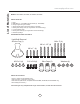
List of Materials www.zephyronline.com MODELS: AK7000BS, AK7036BS, AK7042BS, AK7048BS PARTS SUPPLIED 1 - Hood %DႉH ¿OWHUV 3 - AK7036BS and AK7042BS $.
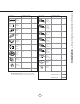
Duct pieces Total 1 Ft. x( ) = Ft. 6”, 7”, 8”, 10” 1 Ft. Round, straight x( ) = Ft. 3-1/ 4” x 10” Rect. 90 0 elbow 15 Ft. x( ) = Ft. 3-1/ 4” x 10” Rect. 45 0 elbow 9 Ft. x( ) = 3-1/ 4” x 10” Rect., straight Equivalent number length x used = Total 3-1/ 4” x 10” 5 Ft. Rect. to 6” round transition x( ) = Ft. 3-1/ 4” x 10” 20 Ft. Rect. to 6” round transition 90 0 elbow x( ) = Ft. 6” round to 1 Ft. 3-1/ 4” x 10” rect. transition x( ) = Ft. Ft. x( ) = Ft. 24 Ft. x( ) = Ft.
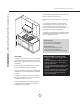
Installation – Mounting Height & Clearance www.zephyronline.com Minimum mount height between range top to hood bottom should be no less than 26”. Maximum mount height should be no higher than 36”. It is important to install the hood at the proper mounting height. Hoods mounted too low could UHVXOW LQ KHDW GDPDJH DQG ¿UH KD]DUG ZKLOH hoods mounted too high will be hard to reach and ZLOO ORVH LWV SHUIRUPDQFH DQG HႈFLHQF\ If available, also refer range manufacturer’s height clearance requirements and reco
1(9(5 H[KDXVW DLU RU WHUPLQDWH GXFW ZRUN LQWR VSDFHV EHWZHHQ ZDOOV FUDZO VSDFHV FHLOLQJ DWWLFV RU JDUDJHV All exhaust must be ducted to the outside. 8VH ULJLG PHWDO GXFWZRUN RQO\ )DVWHQ DOO FRQQHFWLRQV ZLWK VKHHW PHWDO VFUHZV DQG WDSH DOO MRLQWV ZLWK FHUWL¿HG $OXPLQXP 7DSH RU 'XFW 7DSH Some Ducting Options Side wall cap w/ gravity damper Ductless Recirculating Roof Pitch w/ Flashing & Cap Rear Ducting 7 Installation – Ducting Options WARNING FIRE HAZARD
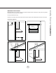
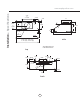
Installation – 6SHFL¿FDWLRQV www.zephyronline.com *9 1/2” or **14 3/16” *8 1/8” or **10 3/8” 4 9/16” 12” 1 5/8” 6” 2” 8 9/16” 37˚ **15 5/16” 11” 3” 1” *7 7/8” or **9 15/16” 22 1/2” R 9/16” side 29 7/8” (30”), 35 7/8” (36”) 41 7/8” (42”), 47 15/16” (48”) * Single Blower Dimension ** Dual Blower Dimension top 11/16” 7 3/8” 4 9/16” 1 1/4” 9 7/8” 4 1/16” 4 9/16” 3 1/4” 2 3/16” rect.
WARNING $OO (OHFWULFDO ZRUN PXVW E\ SHUIRUPHG E\ TXDOL¿HG HOHFWULFLDQ RU SHUVRQ ZLWK VLPLODU WHFKQLFDO NQRZ how and background. )RU SHUVRQDO VDIHW\ UHPRYH KRXVH IXVH RU RSHQ FLUFXLW EUHDNHU EHIRUH EHJLQQLQJ LQVWDOODWLRQ 'R QRW XVH extension cord or adapter plug with this appliance. Follow national electrical codes or prevailing local codes and ordinances.
Installation – Mounting the Range Hood www.zephyronline.com For dual blower installation instructions please refer to page 13. If recirculating range hood refer to the manual included with ZRC-07xxxB recirculating kit or on our website prior to installing hood. Recirculating kit compatible with 650cfm single internal blower only. 5. Duct opening cutout For Mounting Under a Kitchen Cabinet 6HOHFW SUHIHUUHG GXFW ORFDWLRQ YHUWLFDO RU KRUL]RQWDO duct/silver tape %HJLQ LQVWDOODWLRQ E\ UHPRYLQJ W
127( ,I KRUL]RQWDOO\ GXFWLQJ YLD ´ [ ´ UHFWDQJXODU GXFWLQJ WKH PD[LPXP DLUÀRZ RI &)0 ZLOO EH UHGXFHG WR &)0 2WKHU &)0 OHYHOV ZLOO QRW EH DႇHFWHG VERTICAL TO HORIZONTAL DUCTING CONVERSION 5HPRYH VFUHZV DW WRS RI KRRG ERG\ DWWDFKLQJ blower to blower plate. Remove blower from interior of hood body. 1. Disconnect blower plug. A B 5HPRYH VFUHZV IURP LQWHULRU RI KRRG ERG\ attaching blower plate to hood body. Remove blower plate. .
Installation – Horizontal Conversion www.zephyronline.com 5. Place blower inside hood as shown. $WWDFK EORZHU WR KRRG ERG\ IURP WKH EDFN RI KRRG XVLQJ SUHYLRXVO\ UHPRYHG EORZHU screws and reconnect blower plug. 7. Attach 8” round duct collar or 3 1/4”x10” UHFWDQJXODU GXFW FROODU WR EDFN RI KRRG ERG\ XVLQJ 0 [ VFUHZV 8. From inside hood body, position top cover plate to top of hood body.
1. Disconnect blower plug. 5HPRYH VFUHZV DW WRS RI KRRG ERG\ DWWDFKLQJ blower to single blower plate. Remove blower from hood body. 5HPRYH VFUHZV IURP LQVLGH KRRG ERG\ attaching single blower plate. Remove single blower plate from hood body. ,QVWDOO GXDO EORZHU SODWH IURP 3%' $ NLW LQWR KRRG ERG\ $WWDFK E\ VFUHZV SUHYLRXVO\ removed from step 3. ,QVWDOO EORZHU IURP 3%' $ NLW RQWR RWKHU VLGH RI GXDO EORZHU SODWH E\ [ screws. 5.
Installation – PBD-1200A Dual Blower www.zephyronline.com 7. Dual Blower screw mount locations. 8. Connect blower wire extrension cable from 3%' $ NLW WR QHZ EORZHU &RQQHFW ERWK blower plugs. 3ODFH ´ URXQG DGDSWHU LQFOXGHG ZLWK 3%' $ RQ WRS RI KRRG DQG VHFXUH ZLWK M3.5 x 8 screws. NOTE: To secure the 10” transition adapter to top of hood a cut out of 14 1/2” width x 10 1/2” depth will need to be made in the cabinet bottom.
Display (speed level, delay off, filter clean) Lights On/Dim/Off Adjust 6 Speed Levels 5 Min Delay Off 1. Blower On/Off By pressing the blower is switched on and off. When switched on, the blower starts up on speed level 1. ACT Verification - Airflow Control Technology (ACT) allows the installer to set the maximum blower CFM to align with local codes and regulations. - To verify the maximum blower CFM: - With hood off, hold the button for 3-4 seconds. If number 6 displays = default max.
Features & Controls – Touch Controls www.zephyronline.com Charcoal Filter Change Reminder (charcoal filter, if installed) When your hood is installed as a recirculating unit, it is fitted with a set of charcoal filters to purify exhaust and fumes from cooking, then re-circulates the air within the home. These charcoal filters are required to be replaced after every 120 hours of use. The charcoal filters should never be cleaned or placed in a dish washer.
Baffle Filter Clean Indicator When F flashes on the display, the baffle filters needo be cleaned. This will occur after every 30 hours of use. Clean Filters display < F > flashes F Reset the filter clean reminder timer after filters are cleaned and re-installed. With hood off, press and hold for approximately 5 seconds until F on display disappears . The filter clean reminder function is now reset and a new 30 hours elapse cycle is initiated. To Reset hold 5 sec.
Features & Controls – Optional Remote Control www.zephyronline.com FCC Caution: To assure continued compliance, any changes or modifications not expressly approved by the party responsible for compliance could void the user’s authority to operate this equipment. (Example - use only shielded interface cables when connecting to computer or peripheral device. This device complies with Part 15 of the FCC Rules. Operation is subject to the following two conditions.
Do not use corrosive detergents, abrasive detergents or oven cleaners. Do not use any product containing chlorine bleach or any product containing chloride. Do not use steel wool or abrasive scrubbing pads which will scratch and damage surface. Cleaning Stainless Steel &OHDQ SHULRGLFDOO\ ZLWK ZDUP VRDS\ ZDWHU DQG FOHDQ FRWWRQ FORWK RU PLFUR ¿EHU FORWK $OZD\V UXE LQ WKH GLUHFWLRQ RI WKH stainless steel grain. To remove heavier grease build up use a liquid degreaser detergent.
Maintenance – Lights www.zephyronline.com REPLACING LIGHT BULBS CAUTION: Light bulb becomes extremely hot when turned on. '2 127 WRXFK EXOE XQWLO VZLWFKHG Rႇ DQG FRROHG 7RXFKLQJ KRW EXOEV FRXOG FDXVH VHULRXV EXUQV 0DNH VXUH DOO SRZHU LV WXUQHG Rႇ DQG EXOEV DUH QRW KRW 5HPRYH E\ WXUQLQJ EXOE FRXQWHU FORFNZLVH Note: Bulb does not unscrew; it turns 60 degrees, stops and falls out. FIG. 4 ,I EXOEV DUH GLႈFXOW WR WXUQ GXH WR SURORQJHG XVH ¿UPO\ DWWDFK WKH SURYLGHG JODVV VXFWLRQ FXS RU XVH D UXEEHU ODWH[ J
Issue Cause What to do After installation, the unit doesn’t ZRUN 1. The power source is not turned ON. 0DNH VXUH WKH FLUFXLW EUHDNHU DQG WKH XQLW¶V power is ON. 7KH SRZHU OLQH DQG WKH FDEOH ORFNLQJ FRQQHFWRU is not connecting properly. &KHFN WKH SRZHU FRQQHFWLRQ ZLWK WKH XQLW LV connected properly. 3. The switch board and control board wirings are disconnected. 0DNH VXUH WKH ZLULQJV EHWZHHQ WKH VZLWFK board and control board are connected properly. 4.
Wiring Diagrams www.zephyronline.com USE ONLY TYPE MR16, GU10, 35 W. MAX.HALOGEN LIGHT BULBS. AK7000BS, AK7036BS AK7042BS, AK7048BS VOLTS HZ 120 60 CIRCUIT DIAGRAM ACT 390 CFM - Fan Max. 355W @ 2.8A ACT 290 CFM - Fan Max. 255W @ 2.
Some local codes limit the maximum amount of CFM a range hood can move. ACT allows you to control the PD[LPXP EORZHU &)0 RI VHOHFW =HSK\U 9HQWLODWLRQ UDQJH KRRGV ZLWKRXW WKH QHHG IRU H[SHQVLYH PDNH XS DLU NLWV ACT HQDEOHV WKH LQVWDOOHU WR HDVLO\ VHW WKH PD[LPXP EORZHU VSHHG WR RQH RI WZR PRVW FRPPRQO\ VSHFL¿HG &)0 levels; 390 or 290 CFM. The usage of ACT PD\ QRW EH QHFHVVDU\ IRU \RXU LQVWDOODWLRQ 3OHDVH FKHFN \RXU ORFDO codes for CFM restrictions. By default the maximum blower CFM is set to 650.
Fan Curve Diagrams www.zephyronline.
25 Fan Curve Diagrams
List of Parts and Accessories www.zephyronline.com DESCRIPTION PART # Replacement Parts /LJKW %XOE *8 : HDFK %DႉH )LOWHU HDFK RF Remote Control &KDUFRDO )LOWHU HDFK = % 14000005 = ) & Optional Accessories 'XDO ,QWHUQDO %ORZHU .LW Z EORZHU 3%' $ 5HFLUFXODWLQJ .
Three Year Limited Warranty for Parts: For three years from the date of your original purchase of the Products, we will provide, free of charge, Products or parWV LQFOXGLQJ /(' OLJKW EXOEV LI DSSOLFDEOH WR UHSODFH WKRVH WKDW IDLOHG GXH WR manufacturing defects subject to the exclusions and limitations below. We may choose, in our sole discretion, to repair or replace parts before we elect to replace the Products.
www.zephyronline.com PRODUCT REGISTRATION Congratulations on your Zephyr range hood purchase! Please take a moment to register your new range hood at www.zephyronline.com/registration IT’S IMPORTANT Prompt registration helps in more ways than one. Ensures warranty coverage should you need service. Ownership verification for insurance purposes. Notification of product changes or recalls. Zephyr Ventilation | 2277 Harbor Bay Pkwy. | 28 Alameda, CA 94502 | 1.888.880.
Guide d’utilisation, d’entretien et d’installation www.zephyronline.com Tempest I AK7000BS AK7036BS AK7042BS AK7048BS Numéro de modèle : Numéro de série : Date d’achat : Détaillant: MAR19.0401 © Zephyr Ventilation LLC.
www.zephyronline.
INSTALLATION Feuille de calcul pour le conduit...................................................................................5 Espace libre et hauteur de montage...........................................................................6 Options d’installation pour le conduit..........................................................................7 6SpFL¿FDWLRQV........................................................................................................................
www.zephyronline.com Mise en garde de sécurité LISEZ ET CONSERVEZ CES INSTRUCTIONS AVERTISSEMENT POUR RÉDUIRE LES RISQUES D’INCENDIE OU DE DÉCHARGE ÉLECTRIQUE, N’UTILISEZ PAS CET APPAREIL AVEC UN TABLEAU DE COMMANDE À SEMI-CONDUCTEURS.
POUR RÉDUIRE LES RISQUES D’INCENDIE, N’UTILISEZ QUE DES CONDUITS D’AÉRATION EN MÉTAL. ATTENTION 3RXU UpGXLUH OHV ULVTXHV G¶LQFHQGLH HW SRXU pYDFXHU O¶DLU FRQYHQDEOHPHQW DVVXUH] YRXV GH FDQDOLVHU O¶DLU j O¶H[WpULHXU GH la maison. N’installez pas l’échappement du conduit dans les espaces entre les murs, le plafond, le grenier, les vides sanitaires ou le garage. Cet appareil n’est pas conçu pour être utilisé à l’extérieur.
Liste du matériel www.zephyronline.com MODÈLES : AK7000BS, AK7036BS, AK7042BS, AK7048BS PIÈCES FOURNIES 1 - Hotte )LOWUHV GpÀHFWHXUV 3 - AK7036BS et AK7042BS $.
= Longueur x Nombre utilisé Pièces de conduit Total 1 pi x( ) = pi 6”, 7”, 8”, 10” 1 pi circ., droit x( ) = pi 3-1/ 4” x 10” rect., coude à 90º 15 pi x( ) = pi 3-1/ 4” x 10” rect., coude à 45º 9 pi x( ) = pi 6” circ. à rect. de 3-1/4" x 10" 3-1/ 4” x 10” rect., droit ) = pi x( ) = pi x( ) = pi x( ) = pi x( ) = pi 23 pi 7” circ. à rect. de 3-1/4" x 10", coude à 90º x( ) = pi 3-1/ 4” x 10” 30 pi embout mural rect.
Installation – Espace libre et hauteur de montage www.zephyronline.com adaptateurs sont nécessaires, installez-les le plus loin possible de l’ouverture et le plus éloigné possible l’un de l’autre. La hauteur de montage de la surface de la FXLVLQLqUH DX EDV GH OD KRWWH QH GHYUDLW SDV rWUH inférieure à 26”. La hauteur de montage maximale ne devrait pas outrepasser 36”.
N’évacuez ou ne terminez JAMAIS l’échappement du conduit dans les espaces entre les murs, les vides sanitaires, le plafond, le grenier, ou le garage. Tous les échappements doivent être dirigés à l’extérieur de la maison.
Installation – 6SpFL¿FDWLRQV www.zephyronline.com *9 1/2” ou **14 3/16” *8 1/8” or **10 3/8” 4 9/16” 12” 1 5/8” 6” 2” 8 9/16” 37˚ **15 5/16” 11” 3” 1” *7 7/8” or **9 15/16” 22 1/2” R 9/16” Côté 29 7/8” (30”), 35 7/8” (36”) 41 7/8” (42”), 47 15/16” (48”) * Dimensions pour le ventilateur simple ** Dimensions pour le ventilateur double Dessus 11/16” 4 9/16” 7 3/8” 1 1/4” 9 7/8” 4 1/16” 4 9/16” 3 1/4” 2 3/16” L/C rect. L/C circ.
AVERTISSEMENT 7RXV OHV WUDYDX[ pOHFWULTXHV GRLYHQW rWUH UpDOLVpV SDU XQ pOHFWULFLHQ TXDOL¿p RX XQH SHUVRQQH DYHF l’expérience technique et le savoir-faire nécessaires. Pour votre sécurité, enlevez le fusible ou éteignez le disjoncteur de circuit avant de commencer l’installation. 1¶XWLOLVH] SDV GH UDOORQJH pOHFWULTXH RX G¶DGDSWDWHXU DYHF FHW pOHFWURPpQDJHU Suivez le code électrique national ou les codes et réglementations en vigueur.
Installation – Installation de la hotte www.zephyronline.com Veuillez vous rapporter à la page 13 pour obtenir les instruction d’installation d’un ventilateur double. Si vous utilisez le mode de recirculation d’air, consultez le manuel accompagnant la trousse de récupération d’air ZRC-07xxxB ou notre site Web avant de procéder à l’installation de la hotte. La trousse de recirculation d’air n’est compatible qu’avec les ventilateurs internes simples de 650 pi3/min. 5.
NOTE : Si vous souhaitez installer un conduit horizontal rectangulaire de 3-1/4” x 10”, le débit d’évacuation d’air maximal de 650 pi3/min sera réduit à 550 pi3/min. Il n’y aura pas de conséquences sur les autres niveaux de pi3/min. CONVERSION D’UN CONDUIT VERTICAL À UN CONDUIT HORIZONTAL (QOHYH] OHV TXDWUH YLV GH OD SDUWLH VXSpULHXUH GH OD KRWWH TXL UHWLHQQHQW OH YHQWLODWHXU j OD SODTXH 5HWLUH] OH YHQWLODWHXU GH O¶LQWpULHXU GX bâti de la hotte.
Installation – Conversion horizontale www.zephyronline.com 5. Placez le ventilateur à l’intérieur de la hotte, comme illustré. 6. Fixez le ventilateur au bâti de la hotte à partir GH O¶DUULqUH GH OD KRWWH j O¶DLGH GHV TXDWUH vis de ventilateur préalablement enlevées et UHEUDQFKH] OD ¿FKH GX YHQWLODWHXU 7. Fixez le collier de conduit circulaire de 8” ou UHFWDQJXODLUH GH ´[ ´ j O¶DUULqUH GX EkWL GH OD KRWWH j O¶DLGH GH TXDWUH YLV 0 [ 8.
'pEUDQFKH] OD ¿FKH GX YHQWLODWHXU (QOHYH] OHV TXDWUH YLV GH OD SDUWLH VXSpULHXUH GH OD KRWWH TXL UHWLHQQHQW OH YHQWLODWHXU j OD SODTXH GX YHQWLODWHXU VLPSOH 5HWLUH] OH ventilateur du bâti de la hotte. (QOHYH] OHV TXDWUH YLV GH O¶LQWpULHXU GH OD KRWWH TXL UHWLHQQHQW OD SODTXH GX YHQWLODWHXU VLPSOH DX EkWL 5HWLUH] OD SODTXH GX YHQWLODWHXU simple du bâti de la hotte. ,QVWDOOH] OD SODTXH GX YHQWLODWHXU GRXEOH GH OD trousse du PBD-1200A dans le bâti de la hotte.
Installation – Ventilateur double PBD-1200A www.zephyronline.com 7. Emplacements des vis du ventilateur double. 8. Branchez le câble d’extension de la trousse PBD-1200A kit au nouveau ventilateur.
Lumières Allumer/Veilleuse/Éteindre Choix de 6 vitesses Arrêt à retardement (5 min.) 1. Ventilateur : Marche/Arrêt Appuyez sur pour allumer ou éteindre le ventilateur. Lorsque vous l’allumez, le ventilateur se met en marche à la vitesse 1. Vérification de la ACT - La technologie de contrôle du débit d’air permet à l’installeur d’ajuster la quantité maximale d’évacuation de pi3 /min du ventilateur afin de respecter les codes et règlements en vigueur.
Commandes - &RPPDQGHV j HIÀHXUHPHQW HW FDUDWpULVWLTXHV www.zephyronline.com Indicateur de changement des filtres à charbon (si installés) Lorsque la hotte est installée en mode de récupération d’air, elle est munie d’un jeu de filtres à charbon conçus pour purifier la fumée de cuisson et remettre l’air en circulation dans la maison. Ces filtres à charbon doivent être remplacés toutes les 120 heures d’utilisation. Ne nettoyez jamais des filtres à charbon et ne les mettez jamais au lave-vaisselle.
Indicateur de nettoyage des filtres déflecteurs Lorsque l’icône F se met à clignoter sur l’afficheur, les filtres déflecteurs doivent être nettoyés, car 30 heures d’utilisation se sont écoulées. Une fois que les filtres ont été nettoyés et réinstallés, réinitialisez l’indicateur de nettoyage des filtres (avec la hotte hors tension). Lorsque la hotte est éteinte, appuyez environ 5 secondes sur la touche F jusqu’à ce que l’icône disparaisse.
Commandes – Commande à distance optionnelle www.zephyronline.com Mise en garde de la FCC : Dans le but d’assurer une conformité continue, toute modification apportée sans l’approbation expresse du parti responsable de la conformité pourrait annuler l’autorisation de l’utilisateur de faire fonctionner cet appareil. (Exemple – N’utilisez que des câbles d’interface armés lors du branchement à un ordinateur ou à un périphérique.) Cet appareil respecte l’article 15 des réglementations FCC.
1HWWR\H] UpJXOLqUHPHQW OHV VXUIDFHV GH OD KRWWH DYHF GH O¶HDX VDYRQQHXVH FKDXGH HW XQ FKLIIRQ GH FRWRQ propre. N’utilisez pas de détergent abrasif ou corrosif, de laines d’acier ou de tampons à récurer; ils égratigneront et endommageront les surfaces. N’utilisez pas de produits à blanchir au chlore ou d’agents nettoyants « orange ». 3RXU OHV WDFKHV SOXV WHQDFHV XWLOLVH] GX SURGXLW GpJUDLVVDQW OLTXLGH $SUqV OH QHWWR\DJH YRXV SRXYH] SROLU OHV VXUIDFHV DYHF GHV SURGXLWV GH SROLVVDJH j DFLHU LQR[\GDEOH QRQ
Entretien – Lumières www.zephyronline.com REMPLACEMENT DES AMPOULES ATTENTION : Les ampoules deviennent extrêmement chaudes lorsqu’allumées. Veuillez NE PAS les toucher avant de les avoir éteintes et laissées refroidir. Le contact avec les ampoules chaudes pourrait causer de sérieuses brûlures. $VVXUH] YRXV TXH O¶DOLPHQWDWLRQ pOHFWULTXH HVW FRXSpH HW TXH OHV DPSRXOHV QH VRQW SDV FKDXGHV Enlevez les ampoules en les dévissant dans le sens contraire des aiguilles d’une montre.
Problème Cause Solution $SUqV l’installation, l’appareil ne fonctionne pas. 1. Le bloc d’alimentation n’est pas allumé $VVXUH] YRXV TXH O¶DOLPHQWDWLRQ GX GLVMRQFWHXU et de l’appareil est allumée /HV OXPLqUHV fonctionnent, mais le ventilateur ne tourne pas.
Schéma de câblage www.zephyronline.
&HUWDLQV FRGHV HW UqJOHPHQWV OLPLWHQW OD TXDQWLWp PD[LPDOH GH SL3 PLQ TX¶XQH KRWWH SHXW H[WUDLUH /D $&7 SHUPHW GH FRQWU{OHU OD TXDQWLWp PD[LPDOH GH SL3 PLQ TX¶pYDFXHQW XQ pYHQWDLO GH KRWWHV =HSK\U pOLPLQDQW OD QpFHVVLWp G¶DFKHWHU XQ GLVSRVLWLI G¶DLU d’appoint dispendieux.
Diagrammes des courbes caractéristiques des ventilateurs www.zephyronline.
25 Diagrammes des courbes caractéristiques des ventilateurs
Listes des pièces et des accessoires www.zephyronline.
Une preuve de la date d’achat originale est nécessaire pour obtenir du service lorsque le produit est sous garantie Garantie limitée POUR OBTENIR DU SERVICE SOUS GARANTIE OU POUR TOUTE QUESTION LIÉE À L’ENTRETIEN, veuillez communiquer avec nous au 1-888-880-8368 Zephyr Ventilation, LLC (désigné aux présentes sous le nom de « nous ») garantit au premier acheteur (désigné aux présentes sous le nom de « vous » ou « votre ») de produits Zephyr (les « Produits ») que lesdits produits sont exempts de défauts de
www.zephyronline.com ENREGISTRMENT DU PRODUIT Nous vous félicitons d’avoir acheté une hotte Zephyr. Veuillez prendre un moment pour enregistrer votre nouvelle hotte au www.zephyronline.com/registration C’EST IMPORTANT Cet enregistrement rapide est utile à bien des égards. Il assure la couverture de votre garantie si vous avez besoin de service après-vente. À des fins d’assurance, il permet de confirmer que vous êtes le propriétaire.