WWW.ZEPHYRONLINE.COM Titan Island AK7736BS, AK7742BS, AK7748BS EN Use, Care, and Installation Guide FR Guide d’utilisation, d’entretien et d’installation C TM Airflow Control Technology MAY22.
PRO T I TA N I S L A N D WA L L 2 Titan Island Use, Care, and Installation Guide
Contents ZEPHYRONLINE.COM Page Safety Information............................................................................. 4-6 Types of Safety Warnings.................................................................... 4 General Safety...................................................................................4-5 Operation............................................................................................ 6 Electrical Requirements.........................................................
PRO Safety Information T I TA N I S L A N D WA L L READ AND SAVE THESE INSTRUCTIONS Your safety and the safety of others are very important. We have provided many important safety messages in this manual for your appliance. Always read and obey all safety messages. WARNING WARNING - TO REDUCE THE RISK OF FIRE, ELECTRIC SHOCK, OR INJURY TO PERSONS, OBSERVE THE FOLLOWING: a) Use this unit only in the manner intended by the manufacturer. If you have questions, contact the manufacturer.
Safety Information ZEPHYRONLINE.COM READ AND SAVE THESE INSTRUCTIONS WARNING WARNING - TO REDUCE THE RISK OF INJURY TO PERSONS IN THE EVENT OF A RANGE TOP GREASE FIRE, OBSERVE THE FOLLOWINGa: a) SMOTHER FLAMES with a close-fitting lid, cookie sheet, or metal tray, then turn off the burner. BE CAREFUL TO PREVENT BURNS. If the flames do not go out immediately, EVACUATE AND CALL THE FIRE DEPARTMENT. b) NEVER PICK UP A FLAMING PAN – You may be burned.
PRO Safety Information T I TA N I S L A N D WA L L READ AND SAVE THESE INSTRUCTIONS Operation ► Always leave safety grilles and filters in place. Without these components, operating blowers could catch onto hair, fingers and loose clothing. ► The manufacturer declines all responsibility in the event of failure to observe the instructions given here for installation, maintenance and suitable use of the product.
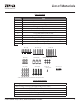
List of Materials ZEPHYRONLINE.COM List of Materials Parts Supplied www.zephyronline.
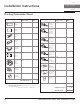
PRO Installation Instructions T I TA N I S L A N D WA L L Ducting Calculation Sheet Equivalent number length x used = Duct pieces 1 Ft. x( ) = Ft. 6”, 7”, 8”, 10” 1 Ft. Round, straight x( ) = Ft. 3-1/ 4” x 10” Rect. 900 elbow 15 Ft. x( ) = Ft. 3-1/ 4” x 10” Rect. 450 elbow 9 Ft. x( ) = 3-1/ 4” x 10” Rect., straight 3-1/ 4” x 10” Rect. 900 flat elbow 24 Ft. x( 7” to 6” or 25 Ft. 8” to 7” Round tapered reducer x( 15 Ft. x( 6”, 7“, 8” Round in-line damper 6”, 7”, 8”, 10” 15 Ft.
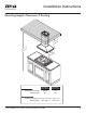
Installation Instructions ZEPHYRONLINE.COM Mounting Height, Clearance, & Ducting A n. i m x. B ma C n. mi x. D ma in..
PRO Installation Instructions T I TA N I S L A N D WA L L Mounting Height, Clearance, & Ducting A minimum of 8” round duct is recommended to maintain maximum air flow efficiency for single blower and 10” round duct for dual internal blower. Both options can be vertically or horizontally ducted. Always use rigid type metal ducts only. Flexible ducts could restrict air flow by up to 50%.
Installation Instructions ZEPHYRONLINE.COM Ducting Options WARNING Fire Hazard: NEVER exhaust air or terminate ductwork into spaces between walls, crawl spaces, ceilings, attics, or garages. All exhaust must be ducted to the outside, unless using the recirculating option. ► Use single wall rigid metal ductwork only. ► Fasten all connections with sheet metal screws and tape all joints w/ certified Silver Tape or Duct Tape.
PRO Installation Instructions T I TA N I S L A N D WA L L Hood Specifications 16-1/8” Standard Min. - 32-1/2” Max. - 50“ 14-5/16” Z1C-0077 (36”, 42“) Z1C-0177 (48”) Min. - 49” Max.
Installation Instructions ZEPHYRONLINE.COM Electrical Supply WARNING Electrical wiring must be done by qualified person(s) in accordance with all applicable codes and standards. Turn off electrical power at service entrance before wiring. For personal safety, remove house fuse or open circuit breaker before beginning installation. Do not use extension cord or adapter plug with this appliance. Follow national electrical codes or prevailing local codes and ordinances.
PRO Installation Instructions T I TA N I S L A N D WA L L Mounting the Hood CAUTION Ceiling Joists 1 Wood Blocking At least two installers are required due to the weight and size of the hood. 2 Top Support Frame 1. Determine mounting location on ceiling and temporarily tape paper template (included with the hood) to the ceiling. Cut out internal shaded area of template to allow the ducting and electrical to pass through. If necessary, add wood blocking (min.
Installation Instructions ZEPHYRONLINE.COM Mounting the Hood 1. 2. top 3. 1/2 bottom FIG. E 3. Attach square support bracket inside the support frame assembly. The placement of the square support bracket should preferably be aligned in the middle where the top and bottom frame intersect (FIG. E1). Install (8) M4 x 8 screws to secure the square support bracket onto the frame. Mount diagonal support brackets onto the support frame assembly facing away from each other in a crossed formation (FIG. E2).
PRO Installation Instructions T I TA N I S L A N D WA L L Mounting the Hood 5. Install the (4) 3/16 x 7/8 mounting screws on top of the four corners of the unit body (FIG. B4). Lift hood and align the mounting screws with the (4) key holes on the bottom of support frame (FIG. F). Slide hood towards the narrow end of key holes to lock into place. Hand tighten each of the (4) screws with a screwdriver to secure to bottom support frame.
Installation Instructions ZEPHYRONLINE.COM PBD-1300B Dual Blower Installation This range hood is equipped standard with a single blower vertical duct option. To convert from single blower vertical ducting to dual blower vertical ducting, please follow the instructions below. 1. Disconnect blower plug and white and black power cables. 2. Remove (4) screws from interior of hood body attaching single blower plate to top of hood body. Remove single blower and single blower plate. 3.
PRO Installation Instructions T I TA N I S L A N D WA L L PBD-1300B Dual Blower Installation 5. Position dual blower inside hood body as shown. Be sure to tuck dual blower plate into blower plate tabs. Secure dual blower by (4) screws previously removed from step 2. 6. Attach 10" round blower collar to top of hood body by (4) M4x8 screws. 7. Attach dual blower PCB to electronics bracket by (4) screws. Refer to wiring diagram on this step.
Features & Controls ZEPHYRONLINE.COM Electronic LCD Controls Power / Delay Off Display Adjust 6 Speed Levels Lights On/Dim/Off 1. Power / Delay Off Power Button Function On/Off button will turn power on and off for entire hood (fan and lights). The hood will remember the last speed and light level it was turned off at. Delay Off Button Function With the fan on, press and hold the On/Off button for three seconds. The fan will change to speed 1 and the 10 minute delay off timer will start.
PRO Features & Controls T I TA N I S L A N D WA L L Electronic LCD Controls Clean Air Clean Air is a feature that turns the fan on every 4 hours for 10 minutes to remove stagnant air in the kitchen. To enable Clean Air Function: With hood off, hold the Fan - button and Fan + button simultaneously for three seconds. The words “CleanAir Function Activated” will illuminate and the fan will turn on speed 1 for 10 minutes. After 10 minutes the fan will turn off and the 4 hour timer will begin.
Features & Controls ZEPHYRONLINE.COM Optional RF Remote Control To order the RF remote control, the part number is 14000005. The blue antenna wire needs to be extended for optimal signal. If using the RF remote control, remove the light panel to extend the antenna. There is no need to secure it. FCC Caution To assure continued compliance, any changes or modifications not expressly approved by the party responsible for compliance could void the user’s authority to operate this equipment.
PRO Features & Controls T I TA N I S L A N D WA L L Optional RF Remote Control RF Remote Features The RF remote control is equipped with a magnet on the back for easy storage. The remote may be placed on any magnetic surface such as a refrigerator or the Zephyr remote holder, FIG. I. The remote holder can be inserted into a standard electrical outlet for easy storage. Note: The remote holder does not charge the RF remote. Maximum remote control communication distance is 15 feet from the liner. FIG.
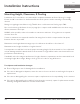
Maintenance ZEPHYRONLINE.COM Hood & Filter Cleaning Surface Maintenance ► Do not use corrosive detergents, abrasive detergents or oven cleaners. ► Do not use any product containing chlorine bleach or any product containing chloride. ► Do not use steel wool or abrasive scrubbing pads which will scratch and damage surface. Cleaning Stainless Steel Clean periodically with warm soapy water and clean cotton cloth or micro fiber cloth. Always rub in the direction of the stainless steel grain.
PRO Maintenance T I TA N I S L A N D WA L L Removing Baffle Filters, FIG. K 1. Push filter away from front of range hood using handles. 2 2. Pivot front of filter downward. 3 1 3. Remove filter by pulling away from hood. Replacing Baffle Filters Hood Model AK7736BS/AK7742BS AK7748BS Part Number 50210036 50210036 Qty. to Order 4 6 2 1 3 FIG. K Swivel LumiLight LED In the unlikely event that your swivel LumiLight LED fails, please contact Zephyr to order replacement parts.
ACT™ Conversion ZEPHYRONLINE.COM Airflow Control Technology (ACT™) Some local codes limit the maximum amount of CFM a range hood can move. ACT™ allows you to control the maximum blower CFM of select Zephyr Ventilation range hoods without the need for expensive make up air kits. ACT™ enables the installer to easily set the maximum blower speed to one of three most commonly specified CFM levels; 590, 390, or 290 CFM. The usage of ACT™ may not be necessary for your installation.
PRO ACT™ Conversion T I TA N I S L A N D WA L L Enabling ACT™ To enable ACT™: 1. Before hood installation, gain access to PC board by following the steps shown on FIG. M. 2. Change plastic jumper positioning as shown in FIG. N to set the desired maximum blower CFM. 3. Re-install PC board and continue with hood installation. 4. Remove the appropriate foil CFM sticker included with the hood literature and place inside the hood body below the wiring diagram or in another clearly visible location.
Wiring Diagram ZEPHYRONLINE.COM Green White Black Wiring Diagram Body Black Black Red Motor Single Blower Body White Black Green White LED LED ANT LED LED RED MOTOR-1 K BLACK WHITE WHITE WHITE BLACK BLACK BLACK WHITE BLACK BLACK B/W Dual Blower B/W WHITE RED MOTOR-2 WHITE 48” model only 48” model only B. LED PCB wire C. Power wire for expansion PCB D. Power wire for expansion PCB E. Blower connection wire F. Blower connection wire G. Control connection wire H.
PRO Troubleshooting T I TA N I S L A N D WA L L Possible Problem After installation, the unit doesn’t work. Light works, but blower is not turning. Possible Cause Solutions The power source is not turned ON. Make sure the circuit breaker and the unit’s power is ON. The power line and the cable locking connector is not connecting properly. The switch board or control board wirings are disconnected. The switch board or control board is defective. The wires on control board are loose.
Troubleshooting ZEPHYRONLINE.COM Possible Problem The hood is not venting out properly. The unit turns on by itself. Filter is vibrating. RF Remote control does not work. Possible Cause Solutions Using the wrong size of ducting. Change the ducting to the correct size. The hood might be hanging to high from the cook top. Adjust the distance between the cook top and the bottom of the hood within 24” and 34” range. Close all the windows and doors to eliminate the outside wind flow.
PRO List of Parts & Accessories T I TA N I S L A N D WA L L Description Replacement Parts Swivel LumiLight LED, 6W Pro Baffle Filter (each) Optional Accessories Dual Internal Blower Make-up Air Kit (Single Blower) Make-up Air Kit (Dual Blower) RF Remote Control Duct Cover Extension (36" & 42") Duct Cover Extension (48", 54", & 60") Part Number Z0B0052 50210036 PBD-1300B MUA008A MUA010A 14000005 Z1C-0077 Z1C-0177 To order parts, visit us online at http://store.zephyronline.com.
Limited Warranty ZEPHYRONLINE.COM Limited Warranty TO OBTAIN SERVICE UNDER WARRANTY OR FOR ANY SERVICE RELATED QUESTIONS United States Customers please call: 1-888-880-8368 or contact us at: zephyronline.com/contact Canada Customers please call: 1-800-361-0799 or Email: service@distinctive-online.
PRO Product Registration T I TA N I S L A N D WA L L Congratulations on the purchase of your Zephyr product! Please take a moment to register your new Zephyr product at www.zephyronline.com/registration IT’S IMPORTANT Prompt registration helps in more ways than one. Ensures warranty coverage should you need service. Ownership verification for insurance purposes. Notification of product changes or recalls. Zephyr Ventilation | 2277 Harbor Bay Pkwy. | Alameda, CA 94502 | 1.888.880.
WWW.ZEPHYRONLINE.COM Titan AK7736BS, AK7742BS, AK7748BS EN Use, Care, and Installation Guide FR Guide d’utilisation, d’entretien et d’installation C TM Airflow Control Technology MAY22.
PRO T I TA N I S L A N D ÎLE 2 Titan Island Guide d’utilisation, d’entretien et d’installation
Table des matières ZEPHYRONLINE.COM Page Consignes de sécurité........................................................................ 4-6 Types d’avertissements de sécurité...................................................... 4 Sécurité générale................................................................................4-5 Opération............................................................................................ 6 Exigences électriques.......................................................
PRO Consignes de sécurité T I TA N I S L A N D ÎLE LISEZ ET CONSERVEZ CES INSTRUCTIONS Votre sécurité et celle des gens qui vous entourent sont très importantes. Ce manuel contient de nombreux messages de sécurité relatifs à votre appareil. Lisez tous les messages et conformez-vous-y en tout temps.
Consignes de sécurité ZEPHYRONLINE.
PRO Consignes de sécurité T I TA N I S L A N D ÎLE LISEZ ET CONSERVEZ CES INSTRUCTIONS Opération ► Laissez toujours les grilles de sécurité et les filtres en place. Sans ces composants, les soufflantes en fonctionnement pourraient s’accrocher aux cheveux, aux doigts et aux vêtements amples. ► Le fabricant décline toute responsabilité en cas de non-respect des instructions données ici pour l’installation, la maintenance et l’utilisation appropriée du produit.
Liste de matériel ZEPHYRONLINE.COM List of Materials Pièces fournies Quantité Partie 1 Hotte www.zephyronline.
PRO Instructions d’installation T I TA N I S L A N D ÎLE Feuille de calcul pour le conduit d’aération Longueur x Nombre utilisé Pièces de conduit = 1 pi x( ) = pi 6”, 7”, 8”, 10” 1 pi circ., droit x( ) = pi 3-1/ 4” x 10” rect., coude à 90º 15 pi x( ) = pi 3-1/ 4” x 10” rect., coude à 45º 9 pi x( ) = pi 6” circ. à rect. de 3-1/4" x 10" pi 16 pi 6” circ. à rect. de 3-1/4" x 10", coude à 90º pi 7” circ. à rect. de 3-1/4" x 10" 3-1/ 4” x 10” rect., droit 3-1/ 4” x 10” rect.
Instructions d’installation ZEPHYRONLINE.COM Hauteur de montage, dégagement et gaine A n. i m x. B ma C n. mi x. D ma in.. m po max 4 2 po 36 o p 36 Hauteur de la hotte min. avec conduit (A) maximum (B) Recouvrement de Prolongement de conduit standard rec. de conduit 32-1/2 po 50 po 49 po 78 po Hauteur de plafond min.
PRO Instructions d’installation T I TA N I S L A N D ÎLE Hauteur de montage, dégagement et gaine Un conduit rond minimum de 8 po est recommandé pour maintenir une efficacité maximale du débit d’air pour un ventilateur simple et un conduit rond de 10 po pour un ventilateur interne double. Les deux options peuvent être canalisées verticalement ou horizontalement. Utilisez toujours uniquement des conduits métalliques de type rigide. Les conduits flexibles peuvent restreindre le débit d’air jusqu’à 50%.
Instructions d’installation ZEPHYRONLINE.COM Options de conduits ATTENTION Risque d’incendie: NE JAMAIS évacuer l’air ni terminer de conduits dans des espaces entre les murs, les vides sanitaires, les plafonds, les greniers ou les garages. Tout l’échappement doit être canalisé vers l’extérieur, à moins d’utiliser l’option de recirculation. ► Utilisez uniquement des conduits métalliques rigides à paroi simple.
PRO Instructions d’installation T I TA N I S L A N D ÎLE Spécifications de la hotte 16-1/8 po La Norme Min. - 32-1/2 po Max. - 50 po 35-15/16 po (36 po) 41-15/16 po (42 po) 47-15/16 po (48 po) Z1C-0077 (36 po, 42 po) Z1C-0177 (48 po) Min. - 49 po Max.
Instructions d’installation ZEPHYRONLINE.COM Fourniture électrique ATTENTION Le câblage électrique doit être effectué par des personnes qualifiées conformément à tous les codes et normes applicables. Cette hotte doit être correctement mise à la terre. Coupez l’alimentation électrique à l’entrée de service avant le câblage. Pour votre sécurité personnelle, retirez le fusible de la maison ou ouvrez le disjoncteur avant de commencer l’installation.
PRO Instructions d’installation T I TA N I S L A N D ÎLE Montage de la hotte AVERTISSEMENT Solives de plafond 1 Bloc de bois Au moins deux installateurs sont nécessaires en raison du poids et de la taille de la hotte. 1. Déterminez l’emplacement de montage au plafond et collez temporairement le gabarit en papier (inclus avec la hotte) au plafond. Découpez la zone ombrée interne du gabarit pour permettre le passage des conduits et de l’électricité. Si nécessaire, ajoutez des blocs de bois (min.
Instructions d’installation ZEPHYRONLINE.COM Montage de la hotte 1. 2. top 3. 1/2 bottom FIG. E 3. Fixez le support carré à l’intérieur de l’assemblage du cadre de support. Le placement du support de support carré doit de préférence être aligné au milieu où les cadres supérieur et inférieur se croisent (FIG. E1). Installez (8) vis M4 x 8 pour fixer le support carré sur le cadre. Montez les supports de support diagonaux sur l’assemblage du cadre de support face à face dans une formation croisée (FIG.
PRO Instructions d’installation T I TA N I S L A N D ÎLE Montage de la hotte 5. Fixez la boîte de jonction au support latéral du cadre de support inférieur à l’aide de (2) vis M4 x 8 mm. (FIG. G). Fixez le fil de la boîte de jonction de la hotte à la boîte de jonction pour soutenir le bras du cadre par (2) attaches à glissière. Cadre de support inférieur (se fixe au dessus du boîtier du ventilateur) retour Trous de clé 6.
Instructions d’installation ZEPHYRONLINE.COM Installation du double ventilateur PBD-1300B Cette hotte de cuisine est équipée de série d’une option de conduit vertical à un seul ventilateur. Pour passer d’un conduit vertical à un ventilateur à un conduit vertical à deux ventilateurs, veuillez suivre les instructions ci-dessous. 1. Débranchez la fiche du ventilateur et les câbles d’alimentation blanc et noir 2.
PRO Instructions d’installation T I TA N I S L A N D ÎLE Installation du double ventilateur PBD-1300B 5. Positionner le ventilateur double à l’intérieur du corps de la hotte comme illustré. Assurezvous de bien insérer la plaque du ventilateur double dans les languettes de la plaque du ventilateur. Fixez le ventilateur double à l’aide des (4) vis précédemment retirées à l’étape 2. 6. Fixez le collier de soufflage rond de 10 po au haut du corps de la hotte à l’aide de (4) vis M4x8. 7.
Fonctionnalités et commandes ZEPHYRONLINE.COM Commandes ACL électroniques Mise en marche/Arrêt à retardement Tableau d’affichage Sélection de la vitesse Lumières - Allumer/Veilleuse/Éteindre 1. Mise en marche/Arrêt à retardement Fonction de mise en marche La touche On/Off permet d’allumer et d’éteindre toutes les fonctions de la hotte (ventilateur et lumières). Lorsqu’elle est éteinte, la hotte garde en mémoire la dernière vitesse du ventilateur et le dernier réglage d’intensité des lumières.
PRO Fonctionnalités et commandes T I TA N I S L A N D ÎLE Commandes ACL électroniques Air pur La fonction d’air pur allume le ventilateur toutes les quatre heures pendant dix minutes pour chasser l’air stagnant de la cuisine. Pour activer la fonction d’air pur: Lorsque la hotte est éteinte, appuyez simultanément sur les touches Fan - et Fan + pendant trois secondes.
Fonctionnalités et commandes ZEPHYRONLINE.COM Télécommande RF en option Pour commander la télécommande RF, la référence est 14000005. Le fil d’antenne bleu doit être rallongé pour un signal optimal. Veuillez consulter la section, Montage de la hotte, pour les instructions. Attention FCC Pour assurer la conformité continue, tout changement ou modification non expressément approuvé par la partie responsable de la conformité peut annuler le droit de l’utilisateur à utiliser cet équipement.
PRO Fonctionnalités et commandes T I TA N I S L A N D ÎLE Télécommande RF en option Caractéristiques de la télécommande RF La télécommande RF est équipée d’un aimant à l’arrière pour un rangement facile. La télécommande peut être placée sur n’importe quelle surface magnétique telle qu’un réfrigérateur ou le support de télécommande Zephyr, FIG. I. Le support à distance peut être inséré dans une prise électrique standard pour un rangement facile.
Entretien ZEPHYRONLINE.COM Nettoyage de la hotte et du filtre Entretien de surface ► N’utilisez pas de détergents corrosifs, de détergents abrasifs ou de nettoyants pour four. ► N’utilisez aucun produit contenant un agent de blanchiment chloré ou un produit contenant du chlorure. ► N’utilisez pas de laine d’acier ou de tampons à récurer abrasifs qui pourraient rayer et endommager la surface.
PRO Entretien T I TA N I S L A N D ÎLE Retrait des filtres déflecteurs, FIG. K 1. Éloignez le filtre de l’avant de la hotte à l’aide des poignées. 2 2. Faites pivoter l’avant du filtre vers le bas. 3 1 3. Retirez le filtre en le tirant hors de la hotte. Remplacement des filtres déflecteurs Modèle de hotte Numéro d’article Qté. commander AK7736BS/AK7742BS 50210036 4 AK7748BS 50210036 6 2 1 3 FIG.
Conversion ACT™ ZEPHYRONLINE.COM Technologie de contrôle du débit d’air (ACT™) Certains codes locaux limitent la quantité maximale de CFM qu’une hotte de cuisinière peut déplacer. ACT™ vous permet de contrôler le CFM maximum du ventilateur de certaines hottes de cuisinière Zephyr Ventilation sans avoir besoin de kits d’air d’appoint coûteux. ACT™ permet à l’installateur de régler facilement la vitesse maximale du ventilateur à l’un des trois niveaux CFM les plus couramment spécifiés; 590, 390 ou 290 CFM.
PRO Conversion ACT™ T I TA N I S L A N D ÎLE Activer ACT™ Pour activer ACT™: 1. Avant l’installation de la hotte, accédez au tableau de circuits imprimés en suivant les étapes illustrées à la FIG. M. 2. Changez le positionnement du cavalier en plastique comme illustré à la FIG. N pour régler le CFM maximum souhaité du ventilateur. 3. Réinstallez la carte de circuit imprimé et poursuivez l’installation de la hotte. 4.
Schéma de câblage Schéma Blanc Noir Vert ZEPHYRONLINE.COM Corps Noir Rouge Noir Corps LED ANT Vert Blanc Blanc Noir Souffleur simple Moteur LED LED LED ROUGE Double ventilateur BLANC/NOIR Modèle 48 po uniquement BLANC BLANC NOIR B. Fil de circuit imprimé LED C.Câble d’alimentation pour PCB d’extension D.Câble d’alimentation pour PCB d’extension E. Fil de connexion du ventilateur F. Fil de connexion du ventilateur G. Fil de connexion de contrôle H.
PRO Dépannage T I TA N I S L A N D ÎLE Problème possible Après l'installation, l'appareil ne fonctionne pas. La lumière fonctionne, mais le ventilateur ne tourne pas. L'unité vibre. L'unité siffle. Le ventilateur fonctionne, mais les LED LumiLight ne le sont pas. 28 Cause possible Solutions La source d'alimentation n'est pas allumée. Assurez-vous que le disjoncteur et l’appareil sont sous tension.
Dépannage ZEPHYRONLINE.COM Problème possible La hotte ne s'échappe pas correctement. Cause possible Utilisation de la mauvaise taille de conduit. Changer le conduit à la bonne taille. La hotte est peut-être suspendue trop haut de la table de cuisson. Ajustez la distance entre la plaque de cuisson et le bas de la hotte dans les limites de 24 po et 34 po. Fermez toutes les fenêtres et portes pour éliminer le vent extérieur.
PRO Liste des pièces et accessoires T I TA N I S L A N D ÎLE La description Pièces de rechange Swivel LumiLight LED, 6 W Filtre Baffle Pro (chacun) Accessoires optionnels Double ventilateur interne Kit d'air d'appoint (ventilateur simple) Kit d'air d'appoint (double ventilateur) Télécommande RF Rallonge de couvercle de conduit (36 po & 42 po) Rallonge de couvercle de conduit (48 po) Numéro d’article Z0B0052 50210036 PBD-1300B MUA008A MUA010A 14000005 Z1C-0077 Z1C-0177 Pour commander des pièces, visite
Garantie limitée ZEPHYRONLINE.COM Garantie limitée POUR OBTENIR UN SERVICE SOUS GARANTIE OU POUR TOUTE QUESTIONS LIÉES AU SERVICE Les clients des États-Unis doivent appeler le: 1-888-880-8368 ou nous contacter à: zephyronline.com/contact Clients du Canada, veuillez appeler: 1-800-361-0799 ou par courriel: service@distinctive-online.
PRO Enregistrement du produit T I TA N I S L A N D ÎLE Nous vous félicitons d’avoir acheté une produit Zephyr. Veuillez prendre un moment pour enregistrer votre nouvelle produit au www.zephyronline.com/registration C’EST IMPORTANT Cet enregistrement rapide est utile à bien des égards. Il assure la couverture de votre garantie si vous avez besoin de service après-vente. À des fins d’assurance, il permet de confirmer que vous êtes le propriétaire.