
Make Up Air Manual


MODELS MUA006A • MUA008A • MUA010A
Page 6
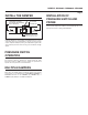
LOCATION OF PROBE AND PRESSURE SWITCH
TYPICAL INSTALLATION WITH
INTERNAL BLOWER AND ROOF VENT
RANGE
HOOD
PROBE
EXHAUST
DUCT
ROOF CAP
w/DAMPER
PRESSURE
SWITCH
HOOD
FLUE
IN-LINE
DAMPER
TYPICAL INSTALLATION WITH
INTERNAL BLOWER AND WALL VENT
RANGE
HOOD
PROBE
EXHAUST
DUCT
PRESSURE
SWITCH
HOOD
FLUE
WALL CAP
w/DAMPER
IN-LINE
DAMPER
TYPICAL INSTALLATION WITH
INTERNAL BLOWER AND HORIZONTAL
DUCTING w/ WALL VENT
RANGE
HOOD
WALL CAP
w/DAMPER
PROBE
TUBING
PRESSURE
SWITCH
KITCHEN
CABINET
TYPICAL INSTALLATION WITH INLINE BLOWER
RANGE
HOOD
PROBE
EXHAUST
DUCT
PRESSURE
SWITCH
HOOD
FLUE
ROOF CAP
w/DAMPER
INLINE
BLOWER
TYPICAL INSTALLATION
WITH EXTERIOR BLOWER
RANGE
HOOD
PROBE
EXHAUST
DUCT
PRESSURE
SWITCH
HOOD
FLUE
EXTERIOR
BLOWER
The probe must be mounted between the range hood damper
and the wall cap, roof cap, in-line blower or external blower.
Mount the probe as close to the hood outlet as possible but
make sure the hood damper operation is not affected.
The pressure switch should be mounted so it is accessible for
anyfutureservice.Theswitchcanmountedno morethen 72”
away from the probe. If longer tubing is required then what is
supplied,purchase1/4”I.D.PVCtubingfromalocalsource.See
the illustrations below for possible installation scenarios.