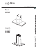
www.zephyronline.com Duo Is. Layers Is.
www.zephyronline.com HOTTE PER CUISINE - Notice d’utilisation...Pag. 25 CAMPANA EXTRACTORA - Manual de utilización...Pag. 48 CAPPA ASPIRANTE - istruzioni per l’uso...Pag.
LIST OF MATERIALS...........................................................................................................pag. 7 DUCTING CALCULATION SHEETS...............................................................................pag. 9 HOOD SPECIFICATION..................................................................................................pag. 10 INSTALLATION - INTERNAL BLOWER.....................................................................................pag.
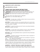
Safety instructions www.zephyronline.com IMPORTANT SAFETY INSTRUCTIONS FOR RESIDENTIAL USE ONLY READ AND SAVE THESE INSTRUCTIONS PLEASE READ ENTIRE INSTRUCTIONS BEFORE PROCEEDING. IMPORTANT: Save these Instructions for the Local Electrical Inspectors use. INSTALLER: Please leave these Instructions with this unit for the owner. OWNER: Please retain these instructions for future reference. Take care when using cleaning agents or detergents.
WARNING – TO REDUCE THE RISK OF INJURY TO PERSONS IN THE EVENT OF A RANGE TOP GREASE FIRE, OBSERVE THE FOLLOWING: A. SMOTHER FLAMES with a close-fitting lid, cookie sheet, or metal tray, then turn off the burner. BE CAREFUL TO PREVENT BURNS. If the flames do not go out mmediately, EVACUATE AND CALL THE FIRE DEPARTMENT. B. NEVER PICK UP A FLAMING PAN – You may be burned. C. DO NOT USE WATER, including wet dishcloths or towels – a violent steam explosion will result. D. Use an extinguisher ONLY if: 1.
Safety instructions www.zephyronline.com through the flue (chimney) of fuel burning equipment to prevent back drafting. Follow the heating equipment manufacturer’s guideline and safety standards such as those published by the National Fire Protection Association (NFPA), and the American Society for Heating, Refrigeration and Air Conditioning Engineers (ASHRAE), and the local code authorities. C. When cutting or drilling into wall or ceiling, do not damage electrical wiring and other hidden utilities. D.
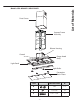
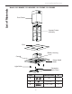
List of Materials Models: ADL-M90ASX / ADL-E42ASX Duct Covers Support Frame Assembly Blower Housing Control Range Hood Body Light Panel Light Bulbs Decorative Mesh Filters TYPE DESCRIPTION N° A M4 1+1 B 1/8" x 1/4" 28 C 1/4" x 2-3/4" 4 -7-
List of Materials www.zephyronline.
Ducting Calculation Sheet Maximum Duct Length: For satisfactory air movement, the total duct length should not exceed 100 equivalent feet.
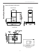
Models: ADL-M90ASX / ADL-E42ASX side of hood front of hood 13" 35-3/8" or 42" Wood Trim Dimensions 1-5/8" Thickness - 10 - 23-5/8" top of hood 11-1/4" Hood Specifications www.zephyronline.
side of hood front of hood top of hood - 11 - Hood Specifications Models: ALL-M90ABX / ALL-M90AWX / ALL-E42AWX / ALL-E42ABX
Installation - Internal Blower www.zephyronline.com The following instructions are for installing the internal blower. CAUTION: To reduce the risk of fire and electric shock, install this rangehood only with internal blower models MT-020 provided with the kit cod CBI-600A. For external and in-line blower preparation please turn to page 14. 1. Remove the (7) screws securing the remote motor support bracket to the motor housing and then remove the bracket. See Fig.1 2.
7. Install the motor and bracket, inside the motor housing, completing the installation using the other screws (6 type B )that have been supplied. (Tot. 13 type B). Fig. 7 8. Connect 9 pin male molex connector from blower wire to 9 pin female molex connector on the capacitor wire. See Fig.8 WARNING! Place electrical wiring inside the blower housing. The hood is now ready to be installed on the wall. - 13 - Installation - Internal Blower 6.
Installation - External & In-Line Blower Preparation www.zephyronline.com The following instructions are for preparing the hood for use with an external or in-line blowers models CBE-1000 or PBN-1000A. CAUTION: To reduce the risk of fire and electric shock, install this rangehood only with remote blowers rated maximum 6.2 A. For internal blower instructions please turn to page 12. 1.
6. Reinstall the cover on the motor housing by following the instructions from step 2 in reverse order. 7. Attach 6 pin male molex connectors to 6 pin female molex connectors inside blower housing. See Fig. 6 Note2: Check local codes to determine minimum wire gauge. See manual included with external and inline blower for instructions on installing the blower. - 15 - Installation - External & In-Line Blower Preparation Note1: A cable lock (not included) may be required by local codes.
Installation - Ducting Options www.zephyronline.com WARNING FIRE HAZARD NEVER exhaust air or terminate duct work into spaces between walls, crawl spaces, ceiling, attics or garages. All exhaust must be ducted to the outside, unless using the recirculating option. Use single wall rigid Metal ductwork only. Fasten all connections with sheet metal screws and tape all joints w/certified Silver Tape or Duct Tape.
B 24" X = C - (4,3-1/16" + 24" + B) MOUNTING TO THE CEILING The following instructions assume the installer has access to the attic or crawl space. Each installation may be unique to the home. 1. Remove the (2) screws to unlock the top support frame from the bottom support frame. Fig.9. Adjust the height by referring to the diagram in Fig. 8. Secure the support frames together with (2 type B) screws per extension arm (Tot. 8 type B). Fig.10 2.
Installation - Mounting the Range Hood www.zephyronline.com into the attic to connect after the hood is installed. Fig.11 3. Place assembled support frames on top of hood and secure it to the hood body using 8 type B screws. Fig.12 4. Place duct covers over assembled support frame until they rest on the hood body. Fig.13 Note! If you ordered a wood trim piece or recirculating kit please refer to the instructions included inside the kits prior to installing the hood to the ceiling.
- Make 4, holes in the ceiling and drive in (3 type C) screws without completely tightening them. Pay attention not to insert the screw into the hole marked with an X on the hole template Fig.14 6. Lift the hood assembly to the ceiling and align the top support frame with the (3) screws previously installed in the ceiling. - Rotate assembly slightly clockwise to lock in place. Fig.15A. Drive in the fourth screw (type C) and tighten the remaining 3 screws to secure the structure in place. Fig.15B 7.
Installation - Power Supply Connection www.zephyronline.com GENERAL • Carefully read the following important information regarding installation safety and maintenance. Keep this information booklet accessible for further consultations. POWER SUPPLY CONNECTION For connection to the power supply refer to the following: 1. Temporarily join the two duct covers by lifting the bottom one and then carefully securing it to the top by using adhesive tape. Fig. 17. Take care not to scratch the duct covers. 2.
- Carry out the power supplly connection in accordance with the national electric code, ANSI/NFPA 70-1999. 5. Replace the lid by following the instructions from step 3 in reverse order, ensuring that the tab on the lid is within the enclosure. 6. Remove adhesive tape and lower the bottom duct cover so it rests on top of the hood body. - 21 - Installation - Power Supply Connection - Connect the electrical conduit to the Field Wiring Compartment using listed onduit fittings.
Maintencance www.zephyronline.com MAINTENANCE • It is recommended to operate the appliance prior to cooking. It is recommended to leave the appliance in operation for 5 minutes after cooking is completed in order to completely eliminate cooking vapors and odors. The proper function of the range hood is conditioned by the regularity of maintenance. • The decorative mesh filters capture the grease particles suspended in the air and are therefore subject to clogging because of frequent use.
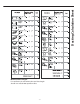
HOOD PART# REPLACEMENT PARTS Light Bulb G4, 20W (each) ADL Z0B0013 Light Bulb GU4, 20W (each) ALL Z0B0030 Recirculating Kit ADL, ALL ZRC-00LL Replacement Charcoal Filters ADL, ALL Z0F-00AC Duct Cover Extension, Short (9” ceiling) ADL, ALL Z1C-00LL Duct Cover Extension, Long (10”-12" ceiling) ADL, ALL Z1C-01LL Wood Trim, 90cm, Wenge ADL-M90ASX AUW-00BR Wood Trim, 90cm, Charcoal ADL-M90ASX AUW-00CH Wood Trim, 42in, Wenge ADL-E42ASX AUW-01BR Wood Trim, 42in, Charcoal ADL-E42ASX A
www.zephyronline.
3LIK0500