www.zephyronline.com ALU-E43 ALU-E63 RANGE HOOD - Installation and use instructions ENGLISH........................................3 FRANÇAIS...................................
-2-
Table of contents Safety Instructions................................................ Page 4 - 5 List of Materials.................................................... Page 6 Ducting Calculation Sheet.................................... Page 7 Hood Specifications.............................................. Page 8 - 9 Wiring Diagram..................................................... Page 10 - 11 Cleaning and Maintenance................................... Page 12 Remote Control............................
READ AND SAVE THESE INSTRUCTIONS ! INTENDED FOR DOMESTIC COOKING ONLY ! WARNING TO REDUCE THE RISK OF FIRE, ELECTRIC SHOCK, OR INJURY TO PERSONS, OBSERVE THE FOLLOWING: 1. Use this unit only in the manner intended by the manufacturer. If you have questions, contact the manufacturer at the address or telephone number listed in the warranty. 2. Before servicing or cleaning unit, switch power off at service panel and lock service panel to prevent power from being switched on accidentally.
WARNING TO REDUCE THE RISK OF INJURY TO PERSONS IN THE EVENT OF A RANGE TOP GREASE FIRE, OBSERVE THE FOLLOWING:* 1. SMOTHER FLAMES with a close- fitting lid, cookie sheet, or metal tray, then turn off the burner. BE CAREFUL TO PREVENT BURNS. If the flames do not go out immediately, EVACUATE AND CALL THE FIRE DEPARTMENT. 2. NEVER PICK UP A FLAMING PAN - You may be burned. 3. DO NOT USE WATER, including wet dishcloths or towels - violent steam explosion will result. 4. Use an extinguisher ONLY if: A.
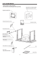
LIST OF MATERIALS - Zephyr blower sold separately - Non-ducted recirculating kit sold separately Connection Air Outlet Assembly (External motor and 2 motors) Electrical system Box Remote Blower Box Cover Hardware Packet Remote Blower Box Remote Blower Wiring Harness Remote Blower Wiring Extension Box Cover (box marked “120 VAC Input”) Box marked “120 VAC Input” Led Driver Box (only model ALU-E63) Mesh Filter -6-
DUCTING CALCULATION SHEET Maximum Duct Length: For satisfactory air movement, the total duct length should not exceed 100 equivalent feet.
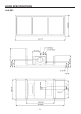
HOOD SPECIFICATIONS ALU-E43 -8-
HOOD SPECIFICATIONS ALU-E63 -9-
WIRING DIAGRAM ALU-E43 - 10 -
WIRING DIAGRAM ALU-E63 - 11 -
CLEANING AND MAINTENANCE Proper maintenance of the Range Hood will assure proper performance of the unit. Motor The motor is permanently lubricated and never needs oiling. If the motor bearings make excessive or unusual noise, replace the motor with the exact service motor. The impeller should also be replaced. Mesh Filters The mesh filters should be cleaned frequently. Using warm water with detergent. Mesh filters are dishwasher safe.
REMOTE CONTROL SYNCHRONIZATION: To synchronize the remote control with the range hood for the first time, proceed as follows: 1. With the range hood off, press and hold the “Power” and “Delay Off” buttons on theremote for 4 seconds (Fig. 1a) until the “Delay Off” indicator on the hood illuminates (Fig.1b). 2. Press the “Delay Off” button on the hood within 4 seconds to confirm the link (Fig. 2).If successful, the “Delay Off” indicator will blink 3 times.
CONTROLS E A B F H G I C D A: Power button - Power Button will turn power on and off for the entire hood (fan and lights). - Hood will remember the last speed and light level it was last turned off at.(Example: hood is turned off at when it was last on high speed and high lights; hood will turn back on at high speed and high lights when Power Button is pressed). B: Fan Speed button - From off, press once for low speed (1), twice for medium (2), and three times for high (3).
Function is enabled. Filter Clean Indicator will continuously blink after 120 hours of unit fan usage indicating it is time to replace the charcoal filter. Indicator light will blink, it will not remain illuminated. - This function must be reset by the user. With hood off, hold the Delay Off Button for five seconds, after five seconds the Filter Clean Indicator will stop blinking and turn off and the 120 hour timer will reset.
REMOTE BLOWERS (EXTERNAL AND IN-LINE) CAUTION: To reduce risk of fire and electric shock, install this range hood only with External Blower Model CBE-1000, and In-Line Blower Model PBN-1000A. Other blowers cannot be substituited. INSTALLING THE DUCTWORK: REMOTE BLOWER NOTE: To reduce the risk of fire, use only metal ductwork. 1. Choose the location where the External Blower or In-Line Blower will be mounted. See illustrations below for mounting location suggestions and restrictions.
INSTALLING THE DUCTWORK: INTERNAL BLOWER ROOF CAP 6” or 10” NOTE: To reduce the risk of fire, use only metal ductwork. round duct 1. Decide where the ductwork will run between the hood and the outside. 2. A straight, short duct run using a minimum 6” round duct (10” round duct for the dual blower) will allow the hood to perform most ef ficiently. 3. Long duct runs, elbows, and transitions will reduce the performance of the hood. Use as few of them as possible. 4. Install a roof cap.
PREPARE THE CEILING OPENING PREPARE THE HOOD SUPPORT The hood should always be centered over the cooktop. Make sure there is adequate space in the ceiling structure to install the hood and ductwork. The hood should be mounted 36” to 72” above the cook top for best removal of cooking impurities. Use joist size lumber to frame in around the range hood opening. The ceiling structure must be able to support the weight of the hood. Fig 7. Model ALU-E43 = 86 pounds. Model ALU-E63 = 102 pounds.
PREPARE THE HOOD 1. Open the perimeter panels and remove the grease filters. See Fig.10. 2. Remove the central panel/s unscrewing the 3,9x6 mm screws. See Fig.11. 3. Remove the (2) interiors panels unscrewing the 3,9x6 mm screws. See Fig.12. Model ALU-E43: remove 8+8 screws. Model ALU-E63: remove 4+4 screws. Model ALU-E43 Model ALU-E63 FIG.10 Model ALU-E43 Model ALU-E63 REMOVE (4+4) MOUNTING SCREWS (3.9 x 6 mm Flat Head) REMOVE (4) MOUNTING SCREWS (3.9 x 6 mm Flat Head) FIG.
INSTALLATION INTERNAL BLOWER NOTE: The following instructions are for installing the internal blower only. Install this range hood only with internal blower model CBI-290A, CBI-600A or PBI1100A. AIR OUTLET “A” AIR OUTLET “B” Hood with 1 internal blower If you choose “A” air outlet (Fig.13): 1.Remove the knockout (Fig.14). 2.Fix internal blower to blower plate and secure using (4) screws supplied with the motor (Fig.15). 3.Install assembly blower/plate by means (2) M4 x 15 mm screws (Fig.16). FIG.
Hood with 1 internal blower If you choose “B” air outlet (Fig.13): 1.Remove the knockout (Fig.17). 2.Install internal blower into blower plate and secure using (4) screws supplied with the motor (Fig.18). 3.Install assembly blower by means (2) M4 x 15 mm screws (Fig.19). Installation Brackets (ONLY non-ducted version): Install the (2) mounting brackets using (4) 3,9 x 6 mm screws (Fig.20). FIG.17 (4) MOUNTING SCREWS (Supplied with the motor) FIG.
Hood with 2 internal blowers The hood with 2 motors can be installed ONLY in ducting version. 1.Remove the (2) knockouts (Fig.21). 2.Install assembly blowers by means (2) M4 x 15 mm screws (Fig.22). 3.Install 10” round collar to the plate by means (2) mounting screws 3.9x6mm (Fig. 23). Fix the assembly round collar/plate to the hood by means (4) 3.9x6 mm screws (Fig.23). FIG.21 (2) MOUNTING SCREWS M4 x15 mm FIG.22 (4) MOUNTING SCREWS (3.9 x 6 mm Flat Head) (2) MOUNTING SCREWS (3.
CONNECT THE WIRES (1 INTERNAL MOTOR) Note: This range hood must be properly grounded. The unit should be installed by a qualified electrician in accordance with all applicable national and local electrical codes. 1. Make connections (A, B,C, D) (Fig.24). 2. Secure capacitor box screwing the (2) 3.9x9.5 mm screws (Fig.24D). A (2) MOUNTING SCREWS (3.9 x 9,5 mm) D GROUND C B FIG.24 CONNECT THE WIRES (2 INTERNAL MOTORS) Note: This range hood must be properly grounded.
INSTALLATION EXTERNAL AND IN-LINE BLOWER AIR OUTLET “A” NOTE: The following instructions are for preparing the hood for use with external or in-line blower models CBE-1000 or PBN1000A. For blower installation details refer to manual included with the blower. AIR OUTLET “B” If you choose “A” air outlet (Fig.26): 1.Remove the knockout (Fig.27). 2.Install 10” round collar to the hood by means (2) mounting screws 3.9x6mm (Fig. 28). FIG.26 FIG.27 10” ROUND COLLAR (2) MOUNTING SCREWS (3.
If you choose “B” air outlet (Fig.26): 1.Remove the (2) knockouts (Fig.29). 2.Install 10” round collar to the plate by means (2) mounting screws 3.9x6mm (Fig. 30). Fix the assembly round collar/plate to the hood by means (4) 3.9x6 mm screws (Fig.30). FIG.29 (4) MOUNTING SCREWS (3.9 x 6 mm Flat Head) (2) MOUNTING SCREWS (3.9 x 6 mm Flat Head) 10” ROUND COLLAR FIG.30 CONNECT THE WIRES (EXTERNAL AND IN-LINE BLOWER) 1. Remove a knockouts (A). See Fig. 31. 2.
INSTALL THE HOOD CAUTION: At least two installers are recommended because of the large size and weight of this range hood. 2x4 WOOD FRAME 1. Re-install the grease filters and control panel (Fig. 10/11). 2. Lift range hood into the ceiling opening. 3. Secure each support frame to the wooden hood support frame using (6) 6 x 60 mm lag bolts and washers provided. Fig. 32. 4. Adjust height of the telescoping support frame to ensure a tight fit between the hood and finished ceiling.
WIRING (EXTERNAL AND IN-LINE BLOWER) 1. Run 4-wire plus ground power cable from the remote blower to the remote blower wiring box marked “motor connection” (Fig.34). 2. Feed 6” of cable through the knockout opening and secure the cable to the wiring box with an appropriate connector. 3. Make electrical connections at the hood (box marked 120 Vac input). Connect white-towhite, black-to-black, green-to-ground (Fig.34). 4. Make electrical connections (remote blower box marked “motor connection”).
COMPLETE THE INSTALLATION 1. Reassemble the (2) interiors panels by means the 3,9x6mm screws. See Fig. 35. Model ALU-E43: use 8+8 screws. Model ALU-E63: use 4+4 screws. 2. Reassemble the central panel/s by means the 3,9x6mm screws. See Fig. 36. 3. Insert the plugs round. See Fig. 37. ALU-E43: insert 8 plugs. Model ALU-E63: insert 4 plugs. Model ALU-E43 Model ALU-E63 USE (8+8) MOUNTING SCREWS (3.9 x 6 mm Flat Head) USE (4+4) MOUNTING SCREWS (3.9 x 6 mm Flat Head) Model ALU-E43 FIG.
INSTALL THE AIR RETURN VENT (NON-DUCTED VERSION) (2) BOLTS Purchase the optional ZRC-00LX recirculating kit, sold separately. The kit includes the air return vent and the charcoal filters. 1. Fix the duct collar on the air return vent, by means (2) M4x8mm screws and (2) bolts. See Fig. 38. (2) MOUNTING SCREWS M4x8mm 2. Fix the air return vent to the ceiling, by means (4) 4,2x15 mm screws. See Fig.39. FIG.38 CEILING (4) MOUNTING SCREWS 4,2x15mm FIG.
MESH FILTERS NOTE: prior to use, remove protective film from the filter frame. NON-DUCTED HOODS ONLY 1. To remove the CHARCOAL filter, grip and push filter tab toward rear of hood. Pull the filter down to disengage the rear filter tabs. 2. To install the CHARCOAL filter, align filter in rectangular opening. Push filter against springs in rear of hood and press into place (Fig.40). Make sure the filter is securely engaged after assembly. 3. Install MESH filter after charcoal filter is installed. 4.
HOOD DESCRIPTION PART# REPLACEMENT PARTS Metal Mesh Filter ALU 50200058 Recirculating Kit ALU ZRC-00LX Replacement Charcoal Filter ALU Z0F-01AC OPTIONAL ACCESSORIES To order parts, visit us online at http://store.zephyronline.com or call us at 1.888.880.
- 32 -
- 33 -
- 34 -
www.zephyronline.
Sommaire Instructions de sécurité............................................... Page 37 - 38 Liste des materiaux..................................................... Page 39 Feuille pour calculer les conduits................................ Page 40 Specifications techniques........................................... Page 41 - 42 Schema electrique...................................................... Page 43 - 44 Nettoyage et entretien................................................. Page 45 Télécommande..
LIRE CES DIRECTIVES ET LES CONSERVER ! CONÇUE POUR LES CUISINES PRIVÉES UNIQUEMENT ! AVERTISSEMENTS POUR RÉDUIRE LES RISQUES D’INCENDIE, D’ÉLECTROCUTION OU DE BLESSURES PHYSIQUES, RESPECTEZ LES INSTRUCTIONS CI-DESSOU: 1. Utilisez cet appareil uniquement de la manière prévue par le fabricant. Si vous avez des ques- tions, contactez le fabricant à l’adresse ou au numéro de téléphone indiqués dans la garantie. 2.
faible ou moyenne température. 7. Ne jamais laisser la cuisinière sans surveillance pendant la cuisson. 8. Utiliser systématiquement des ustensiles de cuisine adaptés au type et à la quantité d’aliments que l’on prépare. AVERTISSEMENTS POUR RÉDUIRE LE RISQUE DE BLESSURES PHYSIQUES EN CAS DE FEU DE FRITURE SUR LA TABLE DE CUISSON, VEUILLEZ PROCÉDER COMME SUIT :* 1. ÉTOUFFEZ LES FLAMMES avec un couvercle hermétique, une plaque à biscuits ou un plateau en métal, puis éteignez le brûleur.
LISTE DES MATERIAUX - Le moteur Zephyr est vendu séparément - Le kit de recirculation non canalisé est vendu séparément Ensemble Raccord sortie air (Ventilateur externe et 2 moteurs) Ensemble tableau electrique Couvercle boîte du ventilateur exterieur Accessoire de fixation Boîte du ventilateur exterieur Harnais Câblage Ventilateur exterieur Exstension Câblage Ventilateur exterieur Couvercle boîte portant inscription “120 VAC Input” Boîte portant inscription “120 VAC Input” Del Boîte du transformateur
FEUILLE POUR CALCULER LES CONDUITS Longueur maximale du conduit : Pour assurer un flux d’air approprié, la longueur maximale d'un conduit, doit pas dépasser une longueur équivalente à 100 piedes.
SPECIFICATIONS TECHNIQUES ALU-E43 - 41 -
SPECIFICATIONS TECHNIQUES ALU-E63 - 42 -
SCHEMA ELECTRIQUE ALU-E43 - 43 -
SCHEMA ELECTRIQUE ALU-E63 - 44 -
NETTOYAGE ET ENTRETIEN Pour assurer les performances de l’appareil, entretenez-le de manière appropriée. Moteur Le moteur est lubrifié en permanence et aucun graissage n’est nécessaire. Si les roulements du moteur font un bruit excessif ou inhabituel, remplacez le moteur par une pièce de rechange identique. Remplacez aussi les hélices. Filtres à graisse Les filtres à graisse doivent être nettoyés souvent. Vous pouvez utiliser de l’eau chaude avec un détergente ou les mettre dans le lave-vaisselle.
TELECOMMANDE SYNCHRONISATION: Pour synchroniser la télécommande avec la hotte de la cuisine, pour la première fois, procéder en suivant les indications suivantes: 1. En tenant arrêtée la hotte de la cuisine, appuyer et maintenir appuyée la touche “Power” et la touche “Delay OFF» sur la télécommande pendant 4 secondes (Fig. 1a) jusqu’à ce que l’indicateur “Delay Off” sur la hotte s’allume (figure 1B). 2. Appuyez la touche “Delay Off” sur la hotte dans les 4 secondes pour confirmer le lien (Fig.2).
FONCTION DES TOUCHES E A B F H G I C D A: Touche Power - La touche d’allumage / extinction sert à mettre en marche et à arrêter la hotte en entier (tur-bine et lumières).
et signale la nécessité de procéder au nettoyage du filtre métallique. La lumière du voyant reste allumée au fixe, sans clignoter. - Cette fonction doit être rétablie par l’utilisateur. Avec la hotte à l’arrêt, maintenez la touche Vitesse turbine enfoncée pendant cinq secondes. Au bout de cinq secondes, le voyant de nettoyage du filtre s’éteint et le réglage de 30 heures repart de zéro.
F : Voyant Vitesse turbine 1 = Petite vitesse 2 = Vitesse moyenne 3 = Grande vitesse - Petite vitesse : seulement le voyant 1 est allumé. - Vitesse moyenne: les voyants 1 et 2 sont allumés. - Grande vitesse : les voyants 1, 2 et 3 sont allumés. - Quand la turbine est à l’arrêt, tous les voyants de vitesse de la turbine sont éteints.
CHOIX DE VENTILATEUR EXTERNE OU “IN-LINE” ATTENTION: Pour réduire les risques d’incendie et électrique, installer cette hotte seulement avec un ventilateur extérieur CBE-1000, et les ventilateur en ligne PBN-1000A uniquement. On ne peut pas utiliser d’autres ventilateurs. INSTALLATION DU SYSTEME D’EVACUATION: VENTILATEUR EXTERNE NOTE: Pour réduire les risques d’incendie n’utiliser que des conduits métalliques. 1. Choisir l’emplacement où le ventilateur externe ou le ventilateur “In-Line” sera monté.
INSTALLER LES CONDUITS (VENTILATEUR INTÉRIEUR) CAPUCHON DU TOIT REMARQUE: pour réduire les risques d’incendie, utilisez uniquement des conduits métalliques. 1. Décidez où le tuyau doit être installé, entre votre hotte et l’extérieur. 2. Un conduit d’évacuation étroit et court (l’aide d’un conduit rond de minimum 6” ou de 10” pour version avec 2 ventilateurs) rendra la hotte plus performante. 3. Un conduits long avec des coudes et des transitions réduira le bon fonctionnement de votre hotte.
PRÉPARATION DE L’OUVERTURE DU PLAFOND La hotte doit être centrée au-dessus de la surface de cuisson. Assurez-vous d’un espace adéquat dans la structure du plafond pour l’installation de la hotte et des conduits. Pour mieux capter les vapeurs de cuisson, la hotte doit être 122 cm (48 po) à 183 cm (72 po) au-dessus de la cuisinière. Utilisez du bois de la taille des solives pour fabriquer une charpente autour de l’ouverture de la hotte.
PRÉPARATION DE LA HOTTE 1. Ouvrir les panneaux de périmètre et enlever les filtres filtre à graisse. Voir Fig. 10. 2. Retirer le panneau/x centrales en devissant les vis 3,9x6 mm. Voir Fig.11. 3. Retirer les (2) panneaux intérieurs en devissant les vis 3,9x6 mm. Voir Fig. 12. Modèle ALU-E43: retirer 8+8 vis. Modèle ALU-E63: retirer 4+4 vis. Model ALU-E43 Model ALU-E63 FIG.10 Modèle ALU-E43 Modèle ALU-E63 RETIRER (4) VIS D’ASSEMBLAGE (3.9 x 6 mm tête plate) RETIRER (4+4) VIS D’ASSEMBLAGE (3.
INSTALLATION VENTILATEUR INTÉRIEUR REMARQUE: Les instructions suivantes permettent d’installer le ventilateur intérieur. Installez cette hotte uniquement avec le moteur intérieur modèles CBI-290A, CBI600A ou PBI-1100A. SORTIE D’AIR “A” SORTIE D’AIR “B” Hotte avec 1 ventilateur intérieur Si vous choisissez la sortie d’air “A” (Fig.13): 1.Enlever la partie pre-coupe (Fig.14). 2.Fixez le ventilateur intérieur à la plaque du ventilateur, en utilisant (4) vis de montage en dotation avec le moteur (Fig.15).
Hotte avec 1 ventilateur intérieur Si vous choisissez la sortie d’air “B” (Fig.13): 1.Enlever la partie pre-coupe (Fig.17). 2.Fixez le ventilateur intérieur à la plaque du ventilateur, en utilisant (4) vis de montage en dotation avec le moteur (Fig.18). 3.Fixez l’esemble ventilateur/plaque en utilisant (2) vis de montage M4 x 15 mm (Fig.19). Installation ètrieres (SEULEMENT pour les versions non canalisée): Installez les (2) étrieres using (4) vis de montage 3,9 x 6 mm (Fig.20). FIG.
Hotte avec 2 ventilateurs intérieur La hotte avec 2 ventilateurs peut être installé seulement en la version canalisée. 1.Enlever les (2) parties pre-coupe (Fig.21). 2.Fixez l’ensemble du ventilateur en utilisant (2) vis de montage M4 x 15 mm (Fig.22). 3.Fixez le raccord rounde de 10” (25cm) à la plaque en utilisant (2) vis de montage 3,9 x 6 mm (Fig.23). Fixez l’ensemble raccord/ plaque à la hotte en utilisant (4) vis de montage 3,9 x 6 mm (Fig.23). FIG.21 (2) VIS DE MONTAGE M4 x15 mm FIG.
CONNECTER LES FILS (1 VENTILATEUR INTÉRIEUR) Remarque: Ce modèle de hotte doit être relié à la terre correctement. Cet article devrait être installé par un électricien qualifié selon les lois nationales et locales en matière d’électricité. 1. Faire les connexions (A, B,C, D) (Fig.24). 2. Fixer la boîte du condensateur au moyens des (2) vis 3.9x9.5 mm (Fig.24D). A (2) VIS D’ASSEMBLAGE (3.9 x 9,5 mm) D TERRE TERRE C B FIG.
INSTALLATION VENTILATEUR EXTERNE OU “IN-LINE” REMARQUE: Les instructions suivantes permettent d’installer le ventilateur externe ou in-line modèles CBE-1000 ou PBN-1000A. Pour plus de détails sur l’installation du ventilateur se référer au manuel inclus dans le ventilateur.
Si vous choisissez la sortie d’air “B” (Fig.26): 1. Enlever les (2) parties pre-coupe (Fig.29). 2.Fixez le raccord rounde de 10” (25cm) à la plaque en utilisant (2) vis de montage 3,9x6 mm (Fig.30). Fixez l’ensemble raccord/ plaque à la hotte en utilisant (4) vis de montage 3,9x6 mm (Fig.30). FIG.29 (4) VIS D’ASSEMBLAGE (3.9 x 6 mm tête plate) (2) VIS D’ASSEMBLAGE (3.9 x 6 mm tête plate) RACCORD ROUND DE 10” (25cm) FIG.30 CONNECTER LES FILS (VENTILATEUR EXTERNE OU “INLINE”) 1.
INSTALLATION DE LA HOTTE ATTENTION : Il est recommandé d’avoir deux installateurs, compte tenu de la taille et du poids de cette hotte. 1. Remonter les filtres à graisse et le panneau du commandes (Fig. 10/11). CADRE DE 2X4 EN BOIS 2. Soulevez la hotte dans l’ouverture du plafond. 3. Fixez chaque cadre de soutien de la hotte à la charpente de bois à l’aide des (6) tirefonds de 6 x 60 mm et rondelles fournis. Fig. 32. 4.
RACCORDEMENT ELECTRIQUE (VENTILATEUR EXTERNE OU “IN-LINE”) 1. Tirer un câble à 4 fils avec la terre du ventilateur externe (ou ventilateur “In-Line”) vers la boîte du ventilateur extérieur de la hotte portant la mention “motor connection” (Fig.34). 2. Alimenter le knockout par un câble de 6” de diamètre et fixer le câble au tableau électrique par un raccord approprié. 3. Faire le branchement électrique à la hotte (boîte portant la mention 120 Vac input).
COMPLETER L’INSTALLATION 1. Remonter les (2) panneaux intérieurs avec vis 3,9x6 mm. Voir Fig. 35. Modèle ALU-E43: utiliser 8+8 vis. Modèle ALU-E63: utiliser 4+4 vis. 2. Remonter le panneau centrale/s avec vis 3,9x6 mm. Voir Fig. 36. 3. Mettez les bouchons rondes. See Fig.37. Modèle ALU-E43: mettez 8 bouchons. Modèle ALU-E63: mettez 4 bouchons. Modèle ALU-E43 Modèle ALU-E63 UTILISER (8+8) VIS D’ASSEMBLAGE (3.9 x 6 mm tête plate) UTILISER (4+4) VIS D’ASSEMBLAGE (3.9 x 6 mm tête plate) FIG.
INSTALLER LA PARTIE POUR LE RETOUR D’AIR (VERSION NON CANALISEE) (2) BOULONS Acheter le kit de recirculation ZRC-00LX option, vendu séparément. Le kit comprend la partie pour le retour d’air et les filtres à charbon. 1. Fixer le collier sur la partie pour le retour d’air en utilisant (2) vis de montage M4x8mm et (2) boulons. Voir Fig. 38. 2. Fixer la partie pour le retour d’air sur le plafond en utilisant (4) vis de montage 4,2x15mm. Voir Fig. 39. (2) VIS DE MONTAGE M4x8mm FIG.
FILTRES REMARQUE: Avant toute utilisation, enlever la pellicule de protection du cadre du filtre à graisse. HOTTES NON CANALISÉES 1. Pour enlever le filtre à charbon, pousser onglet filtre vers l’arrière de la hotte. Inclinez le filtre vers le bas et la retirer. 2. Pour installer le FILTRE À GRAISSE, alignez les onglets du filtre arrière avec ressort dans la hotte. Déroulez la poignée, pousser le filtre en position, puis relâchez (Fig.40). Assurez-vous que le filtre est bien enclenché après l’installation.
HOTTE DESCRIPTION PARTIE# PIÉCES DÉTACHÉES Filtre métallique à graisse ALU 50200058 Kit de Recirculation ALU ZRC-00LX Filtre à Charbon ALU Z0F-01AC ACCESSOIRES EN OPTION Pour commander les pièces détachées, merci de visiter le site http://store.zephyronline.com ou de appeler au numero suivant: 1.888.880.
- 66 -
- 67 -
04308447/5