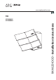
www.zephyronline.
www.zephyronline.com HOTTE PER CUISINE - Notice d’utilisation...Pag. 23 CAMPANA EXTRACTORA - Manual de utilización...Pag. 45 CAPPA ASPIRANTE - istruzioni per l’uso...Pag.
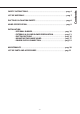
LIST OF MATERIALS...........................................................................................................pag. 7 DUCTING CALCULATION SHEETS...............................................................................pag. 8 HOOD SPECIFICATION.....................................................................................................pag. 9 INSTALLATION - INTERNAL BLOWER.....................................................................................pag.
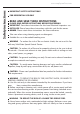
Safety instructions www.zephyronline.com IMPORTANT SAFETY INSTRUCTIONS FOR RESIDENTIAL USE ONLY READ AND SAVE THESE INSTRUCTIONS PLEASE READ ENTIRE INSTRUCTIONS BEFORE PROCEEDING. IMPORTANT: Save these Instructions for the Local Electrical Inspectors use. INSTALLER: Please leave these Instructions with this unit for the owner. OWNER: Please retain these instructions for future reference. Take care when using cleaning agents or detergents.
WARNING – TO REDUCE THE RISK OF INJURY TO PERSONS IN THE EVENT OF A RANGE TOP GREASE FIRE, OBSERVE THE FOLLOWING: A. SMOTHER FLAMES with a close-fitting lid, cookie sheet, or metal tray, then turn off the burner. BE CAREFUL TO PREVENT BURNS. If the flames do not go out mmediately, EVACUATE AND CALL THE FIRE DEPARTMENT. B. NEVER PICK UP A FLAMING PAN – You may be burned. C. DO NOT USE WATER, including wet dishcloths or towels – a violent steam explosion will result. D. Use an extinguisher ONLY if: 1.
Safety instructions www.zephyronline.com through the flue (chimney) of fuel burning equipment to prevent back drafting. Follow the heating equipment manufacturer’s guideline and safety standards such as those published by the National Fire Protection Association (NFPA), and the American Society for Heating, Refrigeration and Air Conditioning Engineers (ASHRAE), and the local code authorities. C. When cutting or drilling into wall or ceiling, do not damage electrical wiring and other hidden utilities. D.
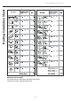
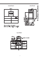
Front Panel Electrical Junction Box Control Light Bulbs Decorative Mesh Filters TYPE DESCRIPTION N° A M4 1+1 B 1/8" x 1/4" 12 C 1/8" x 2/4" 4 D 1/4" x 2-3/4" 6 -7- List of Materials Top Cover
Ducting Calculation Sheet www.zephyronline.com Maximum Duct Length: For satisfactory air movement, the total duct length should not exceed 100 equivalent feet.
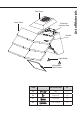
top of hood -9- Hood Specifications side of hood front of hood
Installation - Internal Blower www.zephyronline.com NOTE! The device in this version (with internal suction motor) is equipped for rear discharge of exhaust air. However, if required, it is possible to have the exhaust air discharged from the top. This can be accomplished by following the steps indicated in the following paragraphs; upon reaching step 7, the motor plate must not be rotated, therefore skip steps 8 and 9 and proceed from step 10 directly.
7. Remove the (10 ) screws securing the blower plate to the blower housing and remove blower plate. See. Fig.5 (Note! If air is discharged from the top, do not rotate the plate; proceed from step 10 instead). 8. Remove the rectangular plate and the fixing bracket from the motor plate by loosening the 6 screws. Fig.6 9. Rotate the motor plate by 90° and fix the rectangular plate and the fixing bracket in the opposite direction as shown in Fig.7 10.
Installation - Internal Blower www.zephyronline.com 13. Secure Green/Yellow ground wire connected to the cable to the provided capacitor to blower plate. (type A) Fig. 11 14. Attach the 6 pin male molex connector from blower wire to the 6 pin female molex connector located inside the blower housing. See Fig.12 15. Install the blower and plate on the inside of the blower housing: carry out the instructions at step 3 in reverse order then use the screws provided to complete installation.(Tot.
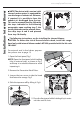
The following instructions are for preparing the hood for use with an external or in-line blowers models CBE-1000 or PBN-1000A. CAUTION: To reduce the risk of fire and electric shock, install this rangehood only with remote blowers rated maximum 6.2 A. For internal blower instructions please turn to page 10. 1. Open the front panel. Fig.1 NOTE! Open the front panel while holding it by its external sides, as shown in Fig.1 , and keep at a suitable distance to avoid impacting it. 2.
Installation - External & In-Line Blower Preparation www.zephyronline.com 5. Close the front panel while holding it by its external sides until it shuts. 6. Remove the metal motor plate by striking it with the aid of a slotted screwdriver. Fig. 4 7 . Remove the (10) screws securing the blower plate to the blower housing and remove blower plate. See Fig.5 8. (if air is discharged from the top, rotate the motor plate by 90° and fix the rectangular plate and the fixing bracket in the opposite direction.
Note1: A cable lock (not included) may be required by local codes. Please review local codes for more information. 12. Attach 6 pin male molex connectors to 6 pin female molex connectors inside blower housing. See Fig 11 Note2: Check local codes to determine minimum wire gauge.
Installation - Ducting Options www.zephyronline.com WARNING FIRE HAZARD NEVER exhaust air or terminate duct work into spaces between walls, crawl spaces, ceiling, attics or garages. All exhaust must be ducted to the outside, unless using the recirculating option. Use single wall rigid Metal ductwork only. Fasten all connections with sheet metal screws and tape all joints w/ certif ed Silver Tape or Duct Tape.
The range hood must be installed at a minimum height of 22 inches (56 cm) from the cooking surface. If a connecting duct work composed of two parts is used, the upper part must be placed outside the lower part. Do not connect the range hood duct to the same duct used to exhaust hot air or fumes from another appliance. Before proceeding with the assembly instructions remove the decorative mesh filters so that the range hood is esier to handle. Min 22" - Max 34" 36" MOUNTING TO THE WALL 1.
Installation - Mounting the Range Hood www.zephyronline.com WARNING: In order to facilitate their connection, make sure that the power supply conduits are not obstructed by the hood. 3. When the hood has been adjusted tighten the screws to secure the hood in place. 4. Once the adjustment has been completed, fix the hood definitely using another (2 type D) screws. NOTE: Screws must be fastened into wooden studs so wood blocking may be necessary.
POWER SUPPLY CONNECTION For connection to the power supply refer to the following: 1. Remove the power supply cover by undoing the (2) screws Fig. 17. 2. Break through the hole on the box. 3. Pass the wires through the hole in the box and fasten the power supply conduit. Fig.18 4. Connect the wires of the hood to those of the power supply as described. Fig.
Maintencance www.zephyronline.com MAINTENANCE • It is recommended to operate the appliance prior to cooking. It is recommended to leave the appliance in operation for 5 minutes after cooking is completed in order to completely eliminate cooking vapors and odors. The proper function of the range hood is conditioned by the regularity of maintenance. • The decorative mesh filters capture the grease particles suspended in the air and are therefore subject to clogging because of frequent use.
HOOD PART# REPLACEMENT PARTS Light Bulb GU5, 20W (each) ATI Z0B0031 Recirculating Kit ATI ZRC-00HZ Replacement Charcoal Filters ATI Z0F-00AC Short Duct Cover (8”-9” ceiling) ATI Z1C-00TI Long Duct Cover (9”-10” ceiling) ATI Z1C-01TI OPTIONAL ACCESSORIES To order parts, visit us online at http://store.zephyronline.com or call us at 1.888.880.
3LIK0505