www.zephyronline.com Incline AIN-M80AWX AIN-M80ASX Wave AWA-M90AWX AWA-M90ABX RANGE HOOD - Installation and use instructions ENGLISH........................................3 FRANÇAIS...................................
-2-
Table of contents Safety Instructions.............................................. Page 4 - 5 List of Materials.................................................. Page 6 - 7 Ducting Calculation Sheet.................................... Page 8 Hood Specifications............................................. Page 9 - 10 Wiring Diagram.................................................... Page 11 Cleaning and Maintenance.................................... Page 12 Remote Control.................................
READ AND SAVE THESE INSTRUCTIONS ! INTENDED FOR DOMESTIC COOKING ONLY ! WARNING TO REDUCE THE RISK OF FIRE, ELECTRIC SHOCK, OR INJURY TO PERSONS, OBSERVE THE FOLLOWING: 1. Use this unit only in the manner intended by the manufacturer. If you have questions, contact the manufacturer at the address or telephone number listed in the warranty. 2. Before servicing or cleaning unit, switch power off at service panel and lock service panel to prevent power from being switched on accidentally.
WARNING TO REDUCE THE RISK OF INJURY TO PERSONS IN THE EVENT OF A RANGE TOP GREASE FIRE, OBSERVE THE FOLLOWING:* 1. SMOTHER FLAMES with a close-fitting lid, cookie sheet, or metal tray, then turn off the burner. BE CAREFUL TO PREVENT BURNS. If the flames do not go out immediately, EVACUATE AND CALL THE FIRE DEPARTMENT. 2. NEVER PICK UP A FLAMING PAN - You may be burned. 3. DO NOT USE WATER, including wet dishcloths or towels - violent steam explosion will result. 4. Use an extinguisher ONLY if: A.
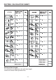
LIST OF MATERIALS Incline - Zephyr blower sold separately - Non-ducted recirculating kit sold separately - Duct cover accessory sold separately Remote Blower Collar with Damper (External motor) Remote Blower Wiring Harness Remote Blower Wiring Extension Remote Blower Box Cover Remote Blower Box Box Cover (box marked “120 VAC Input”) Electrical System Box Box marked “120 VAC Input” Led Hardware Packet Mesh Filter -6-
LIST OF MATERIALS Wave - Zephyr blower sold separately - Non-ducted recirculating kit sold separately - Duct cover accessory sold separately Remote Blower Collar with Damper (External motor) Remote Blower Wiring Harness Remote Blower Wiring Extension Remote Blower Box Cover Remote Blower Box Box Cover (box marked “120 VAC Input”) Electrical System Box Box marked “120 VAC Input” Hardware Packet Led Mesh Filter -7-
DUCTING CALCULATION SHEET Maximum Duct Length: For satisfactory air movement, the total duct length should not exceed 100 equivalent feet.
HOOD SPECIFICATIONS Incline -9-
HOOD SPECIFICATIONS Wave - 10 -
WIRING DIAGRAM - 11 -
CLEANING AND MAINTENANCE Proper maintenance of the Range Hood will assure proper performance of the unit. Motor The motor is permanently lubricated and never needs oiling. If the motor bearings make excessive or unusual noise, replace the motor with the exact service motor. The impeller should also be replaced. Mesh Filters The mesh filters should be cleaned frequently. Using warm water with detergent. Mesh filters are dishwasher safe.
REMOTE CONTROL SYNCHRONIZATION: To synchronize the remote control with the range hood for the first time, proceed as follows: 1. With the range hood off, press and hold the “Power” and “Delay Off” buttons on theremote for 4 seconds (Fig. 1a) until the “Delay Off” indicator on the hood illuminates (Fig.1b). 2. Press the “Delay Off” button on the hood within 4 seconds to confirm the link (Fig. 2).If successful, the “Delay Off” indicator will blink 3 times.
CONTROLS E A B F G H I C D A: Power button - Power Button will turn power on and off for the entire hood (fan and lights). - Hood will remember the last speed and light level it was last turned off at.(Example: hood is turned off at when it was last on high speed and high lights; hood will turn back on at high speed and high lights when Power Button is pressed). B: Fan Speed button - From off, press once for low speed (1), twice for medium (2), and three times for high (3).
fan usage indicating it is time to replace the charcoal filter. Indicator light will blink, it will not remain illuminated. - This function must be reset by the user. With hood off, hold the Delay Off Button for five seconds, after five seconds the Filter Clean Indicator will stop blinking and turn off and the 120 hour timer will reset. Order replacement charcoal filter kit number Z0F-01AC through your local dealer, www.zephyronline.com or the Zephyr customer service department.
INSTALLING THE DUCTWORK: INTERNAL BLOWER ROOF CAP 6” ROUND DUCT NOTE: To reduce the risk of fire, use only metal ductwork. 1. Decide where the ductwork will run between the hood and the outside. 2. A straight, short duct run using a minimum 6” round duct will allow the hood to perform most efficiently. 3. Long duct runs, elbows, and transitions will reduce the performance of the hood. Use as few of them as possible. 4. Install a roof or wall cap.
CHOOSE AIR OUTLET LOCATION The hood is supplied with upper air outlet; but you can let the air out the back, turning the motor plate. Rotation of the motor plate: 1.Remove the motor plate unscrewing (6) screws (Fig.11). 2.Rotate the motor plate and re-fix in the new position (Fig.12). In the installation with internal blower, use the rond knockout (B); in the installation with remote or In-line blower, use the other knockout (A). FIG.11 KNOCKOUT (B) KNOCKOUT (A) FIG.
REMOTE BLOWERS (EXTERNAL AND IN-LINE) CAUTION: To reduce risk of fire and electric shock, install this range hood only with External Blower Model CBE-1000, and In-Line Blower Model PBN-1000A. Other blowers cannot be substituited. INSTALLING THE DUCTWORK: REMOTE BLOWER NOTE: To reduce the risk of fire, use only metal ductwork. 1. Choose the location where the External Blower or In-Line Blower will be mounted. See illustrations below for mounting location suggestions and restrictions. 2.
INSTALLATION EXTERNAL AND IN-LINE BLOWER KNOCKOUT (A) NOTE: The following instructions are for preparing the hood for use with external or in-line blower models CBE-1000 or PBN1000A. For blower installation details refer to manual included with the blower. 1. Remove the knockout (A). Fig. 14. 2. Fix the wiring box marked “Motor Connection” with (2) 3,9x6mm screws and (2) washers (Fig. 15). 3. Install 8” round collar to top of the hood (or rear) screwing the (4) 3.9x9.5 mm screws (Fig.16). FIG.
INSTALL THE HOOD Model Incline Remove the plastic protective film from all exterior surfaces, decorative flues and filters, prior to final installation 1. Construct wood wall framing that is flush with interior surface of wall studs (Fig.17/18). Make sure: a) the framing is centered over installation location. b) the height of the framing will allow the hood to be secured to the framing within the dimensions shown. 2. Determine desired height over cook top and mark hood bottom line.
INTERNAL BLOWER WIRING Note: This range hood must be properly grounded. The unit should be installed by a qualified electrician in accordance with all applicable national and local electrical codes. See Fig.19 for Incline Model, see Fig.20 for Wave Model. 1. Make connections (A, B, C). 2. Secure capacitor box screwing the (2) 3.9x9.5 mm screws (D). 3. Remove the wiring box cover (E). Remove a knockout from the wiring box. 4. Secure the conduit to the wiring box through a conduit connector. 5.
MODEL WAVE CONNECT: WHITE-TO-WHITE, BLACK,-TO-BLACK, GREEN-TO-GROUND. E BOX MARKED “120 VAC INPUT” D WIRING BOX COVER GROUND C B A FIG.
REMOTE BLOWER WIRING 1. Remove one knockout from the wiring box marked “Motor Connection”. 2. Run 4-wire plus ground power cable from the remote blower to the remote blower wiring box marked “motor connection” (Fig.21B). 3. Feed 6” of cable through the knockout opening and secure the cable to the wiring box with an appropriate connector. 4. Make electrical connections at the hood (box marked 120 Vac input). Connect white-towhite, black-to-black, green-to-ground (Fig.21A). 5.
MODEL WAVE WHITE(COMMON) BLACK(HIGH) BLUE(MED) RED(LOW) GREEN(GROUND) HOOD WIRE HARNESS REMOTE BLOWER BOX MARKED VAC INPUT” A “120 B CONNECT: WHITE-TO-WHITE, BLACK,-TO-BLACK, GREEN-TO-GROUND. GROUND REMOTE BLOWER BOX CONNECT: WHITE-TO-WHITE, BLACK-TO-BLACK, BLUE-TO-BLUE RED-TO-RED GREEN-TO-GROUND. FIG.
INSTALL DUCT COVERS (DUCTED VERSION) MOUNTING SCREWS (3.9 x 6 mm Flat Head) Purchase the optional Z1C-00IN Flue duct cover, sold separately. The kit includes the duct cover and duct cover mounting bracket. 1.Assemble the duct cover mounting bracket, adjusting outside width as shown (Fig.22). 2.Carefully center the mounting bracket directly over the range hood location. 3.Secure the bracket assembly to the ceiling using (2) 4.8 x 38mm mounting screws and drywall anchors (Fig.23).
7. Install upper and lower duct covers onto the range hood (Fig.25). 8. Secure upper duct cover to flue mounting bracket with (2) 3.9 x 6 mm screws (Fig.26). UPPER DUCT COVER LOWER DUCT COVER FIG.25 3.9 x 6 mm Flat Head SCREWS FIG.
NON-DUCTED INSTALLATION Purchase Non-ducted Recirculating Kit from your local dealer, sold separately. The kit includes the charcoal filter/s and the top cover. Ref. ZRC-00IN (Mod. Incline) Ref. ZRC-00WA (Mod. Wave) Fix the top cover with (3) 3,9 x 6mm mounting screws working from inside the hood (Fig. 27). Model Incline Install the CHARCOAL filters, place it over the mesh filter and lock it with a charcoal filter holders (Fig.28). Make sure the filter is securely engaged after assembly.
COMPLETE THE INSTALLATION Model Incline Upper mesh filter Model Incline Re-install the mesh filters (see section “MESH FILTERS”). Reassemble the front panel. See instructions of Fig.8, proceeding in revers order. Model Wave Reassemble the metal panel and the lower glass. See Fig. 10 and 9. MESH FILTERS FIG.31 NOTE: prior to use, remove protective film from the filter frame. Model Incline DUCTED AND NON-DUCTED HOODS Model Incline 1. To remove the upper MESH filter, remove the front panel (Fig.31).
32). Remove the charcoal filter holders (Fig.34). Remove also the charcoal filter located in the lower mesh filter. 2. To install the CHARCOAL filters, place it over the mesh filter and lock it with a charcoal filter holders (Fig.34). Make sure the filter is securely engaged after assembly. 3. Install MESH filters after charcoal filters are installed. 4. The charcoal filters replacement model is ZOF-02AC. Model Wave 1. To remove the CHARCOAL filter, open the upper front glass (Fig.
HOOD DESCRIPTION PART# REPLACEMENT PARTS Metal Mesh Filter AIN 50200056 Metal Mesh Filter AWA 50200057 Recirculating Kit AIN ZRC-00IN Recirculating Kit AWA ZRC-00WA Replacement Charcoal Filters AIN Z0F-02AC Replacement Charcoal Filters AWA Z0F-01AC Duct Cover Kit AIN Z1C-00IN Duct Cover Kit AWA Z1C-00IN OPTIONAL ACCESSORIES To order parts, visit us online at http://store.zephyronline.com or call us at 1.888.880.
- 31 -
- 32 -
www.zephyronline.
Sommaire Instructions de sécurité........................................ Page 35 - 36 Liste des materiaux..............................................Page 37 - 38 Feuille pour calculer les conduits...........................Page 39 Specifications techniques..................................... Page 40 - 41 Schéma eléctrique...............l.............................. Page 42 Nettoyage et entretien.......................................... Page 43 Télécommande............................................
LIRE CES DIRECTIVES ET LES CONSERVER ! CONÇUE POUR LES CUISINES PRIVÉES UNIQUEMENT ! AVERTISSEMENTS POUR RÉDUIRE LES RISQUES D’INCENDIE, D’ÉLECTROCUTION OU DE BLESSURES PHYSIQUES, RESPECTEZ LES INSTRUCTIONS CI-DESSOU: 1. Utilisez cet appareil uniquement de la manière prévue par le fabricant. Si vous avez des questions, contactez le fabricant à l’adresse ou au numéro de téléphone indiqués dans la garantie. 2.
AVERTISSEMENTS POUR RÉDUIRE LE RISQUE DE BLESSURES PHYSIQUES EN CAS DE FEU DE FRITURE SUR LA TABLE DE CUISSON, VEUILLEZ PROCÉDER COMME SUIT :* 1. ÉTOUFFEZ LES FLAMMES avec un couvercle hermétique, une plaque à biscuits ou un plateau en métal, puis éteignez le brûleur. SOYEZ PRUDENT(E) AFIN D’ÉVITER LES BRÛLURES. Si les flammes ne s’éteignent pas immédiatement, ÉVACUEZ LE LIEU ET APPELEZ LE SERVICE DES POMPIERS. 2. NE SAISISSEZ JAMAIS UNE POÊLE ENFLAMMÉE, vous risquez de vous brûler. 3.
LISTE DES MATERIAUX Incline - Le moteur Zephyr est vendu séparément. - Le kit de recirculation est vendu séparément. - L’accessoire de conduit décoratif est vendu séparément.
LISTE DES MATERIAUX Wave - Le moteur Zephyr est vendu séparément. - Le kit de recirculation est vendu séparément. - L’accessoire de conduit décoratif est vendu séparément.
FEUILLE POUR CALCULER LES CONDUITS Longueur maximale du conduit : Pour assurer un flux d’air approprié, la longueur maximale d'un conduit, doit pas dépasser une longueur équivalente à 100 piedes.
SPECIFICATIONS TECHNIQUES Incline - 40 -
SPECIFICATIONS TECHNIQUES Wave - 41 -
SCHEMA ELECTRIQUE - 42 -
NETTOYAGE ET ENTRETIEN Pour assurer les performances de l'appareil, entretenez-le de manière appropriée. Moteur Le moteur est lubrifié en permanence et aucun graissage n'est nécessaire. Si les roulements du moteur font un bruit excessif ou inhabituel, remplacez le moteur par une pièce de rechange identique. Remplacez aussi les hélices. Filtres à graisse Les filtres à graisse doivent être nettoyés souvent. Vous pouvez utiliser de l’eau chaude avec un détergente ou les mettre dans le lave-vaisselle.
TELECOMMANDE SYNCHRONISATION: Pour synchroniser la télécommande avec la hotte de la cuisine, pour la première fois, procéder en suivant les indications suivantes: 1. En tenant arrêtée la hotte de la cuisine, appuyer et maintenir appuyée la touche “Power” et la touche “Delay OFF» sur la télécommande pendant 4 secondes (Fig. 1a) jusqu’à ce que l’indicateur “Delay Off” sur la hotte s’allume (figure 1B). 2. Appuyez la touche “Delay Off” sur la hotte dans les 4 secondes pour confirmer le lien (Fig.2).
FONCTION DES TOUCHES E A B F H G I C D A: Touche Power - La touche d’allumage / extinction sert à mettre en marche et à arrêter la hotte en entier (tur-bine et lumières).
et signale la nécessité de procéder au nettoyage du filtre métallique. La lumière du voyant reste allumée au fixe, sans clignoter. - Cette fonction doit être rétablie par l’utilisateur. Avec la hotte à l’arrêt, maintenez la touche Vitesse turbine enfoncée pendant cinq secondes. Au bout de cinq secondes, le voyant de nettoyage du filtre s’éteint et le réglage de 30 heures repart de zéro.
Note2: La fonction d’air propre reste activée même si les lumières sont allumées/éteintes. F : Voyant Vitesse turbine 1 = Petite vitesse 2 = Vitesse moyenne 3 = Grande vitesse - Petite vitesse : seulement le voyant 1 est allumé. - Vitesse moyenne: les voyants 1 et 2 sont allumés. - Grande vitesse : les voyants 1, 2 et 3 sont allumés. - Quand la turbine est à l’arrêt, tous les voyants de vitesse de la turbine sont éteints.
INSTALLER LES CONDUITS (VENTILATEUR INTÉRIEUR) CAPUCHON DU TOIT CONDUIT ROND DE 6” (15 cm) REMARQUE: pour réduire les risques d’incendie, utilisez uniquement des conduits métalliques. 1. Décidez où le tuyau doit être installé, entre votre hotte et l’extérieur. 2. Un conduit droit et court (l'aide d'un conduit rond de minimum 6”) permettra à votre hotte de fonctionner d’une façon plus efficace. 3. Un conduits long avec des coudes et des transitions réduira le bon fonctionnement de votre hotte.
CHOISIR LA SORTIE DE L’AIR La hotte est livrée avec sortie d'air supérieure; mais vous pouvez laisser l'air à l'arrière, en tournant la plaque du moteur. Rotation de la plaque de moteur: 1. Retirez la plaque du moteur en dévissant (6) vis (Fig.11). 2. Tourner la plaque du moteur et re-fix dans la nouvelle position (Fig.12). Dans l'installation avec ventilateur interieur, utilisez la partie pre-coupe ronde (B); dans l'installation avec ventilateur externe ou In-Line, utiliser l'autre partie pre-coupe (A).
VENTILATEUR EXTERNE (EXTERIEUR OU “IN-LINE”) ATTENTION: Pour réduire les risques d’incendie et électrique, installer cette hotte seulement avec un ventilateur extérieur CBE-1000, et les ventilateur en ligne PBN-1000A uniquement. On ne peut pas utiliser d’autres ventilateurs. INSTALLATION DU SYSTEME D’EVACUATION: VENTILATEUR EXTERNE NOTE: Pour réduire les risques d’incendie n’utiliser que des conduits métalliques. 1. Choisir l’emplacement où le ventilateur externe ou le ventilateur “In-Line” sera monté.
IINSTALLATION VENTILATEUR EXTERNE OU “IN-LINE” PARTIE PRE-COUPE (A) REMARQUE: Les instructions suivantes permettent d’installer le ventilateur externe ou in-line modèles CBE-1000 ou PBN-1000A. Pour plus de détails sur l'installation du ventilateur se référer au m 1. Enlever la partie pre-copue (A). Fig. 14. 2. Fixer la boîte de connexion électrique portant l’inscription “Motor Connection” au moyens de (2) vis 3,9 x 6mm et (2) rondelles (Fig.15). 3.
Modèle Incline Remarque : avant l'installation finale, retirez la pellicule en plastique de toutesles surfaces extérieures, de conduit décoratif et des filtres. 1. Construisez une structure murale en bois à niveau avec la surface intérieure des poteaux de cloison (Fig.17/18). Assurez-vous: a) que la structure est centrée sur l'emplacement d'installation. b) que la structure soit placée à une hauteur permettant d'y fixer le support de montage conformément aux dimensions indiquées. 2.
INSTALLATION ELECTRIQUE VENTILATEUR INTÉRIEUR Remarque: Ce modèle de hotte doit être relié à la terre correctement. Cet article devrait être installé par un électricien qualifié selon les lois nationales et locales en matière d’électricité. Voir la Figure 19 pour le modèle Incline, voir la Figure 20 pour le modèle Wave. 1. Faire les connexions (A,B, C). 2. Fixer la boîte du condensateur au moyens des (2) vis 3.9x9.5 mm (D). 3. Enlevez le couvercle (E) de la boîte de connexion électrique.
MODELE WAVE BRANCHER: LE BLANC AVEC LE BLANC, LE NOIR AVEC LE NOIR, VERT AVEC LA TERRE. E BOÎTE PORTANT INSCRIPTION “120 VAC INPUT” D COUVERCLE BOÎTE DE CONNEXION ELECTRIQUE TERRE C B A FIG.
INSTALLATION ELECTRIQUE VENTILATEUR EXTERNE 1. Ouvrez un trou de la boîte de connexion électrique portant l’inscription “Motor Connection”. 2. Tirer un câble à 4 fils avec la terre du ventilateur externe (ou ventilateur “In-Line”) vers la boîte de connexion électrique de la hotte portant la mention “motor connection” (Fig.21B). 3. Alimenter le knockout par un câble de 6” de diamètre et fixer le câble au tableau électrique par un raccord approprié. 4.
MODELE WAVE BLANC(COMMUN) NOIR(ELEVE) BLU(MOYENNE) ROUGE(FAIBLE) VERT(TERRE) CÂBLAGE HOTTE VENTILATEUR EXTERNE BOÎTE PORTANT INSCRIPTION “120 VAC INPUT” A BRANCHER: LE BLANC AVEC LE BLANC, LE NOIR AVEC LE NOIR, VERT AVEC LA TERRE. BOÎTE DU VENTILATEUR EXTERIEUR TERRE B BRANCHER: LE BLANC AVEC LE BLANC, LE NOIR AVEC LE NOIR, LE BLU AVEC LE BLU LE RED AVEC LE RED LE VERT AVEC LA TERRE. FIG.
INSTALLATION DECORATIF CANALISE) CONDUIT (VERSION VIS DE MONTAGE (3.9 x 6 mm Tête plate) Achetez le kit conduit decoratif Z1C00IN en option, vendu séparément. Le kit comprend le conduit decoratif et le support de montage du conduit. 1.Montez le support de montage du conduit décoratif en réglant la largeur extérieur comme indiqué. (Fig.22) 2.Centrez avec soin le support de montage directement au-dessus de l'emplacement de la hotte de cuisine. 3.
approprié avec clapêt à évacuer l’air vers l’extérieur. 6. Scellez tous les joints des conduits avec du ruban adhésif en aluminium. 7. Installer les conduit décoratif inférieur et supérieur sur la hotte (Fig.25). 8. Fix le conduit décoratif supérieur à le support de montage avec (2) vis 3.9 x 6 mm (Fig.26). CONDUIT DECORATIF SUPERIEUR CONDUIT DECORATIF INFERIEUR FIG.25 VIS DE MONTAGE (3.9 x 6 mm Tête plate) FIG.
INSTALLATION CANALISEE NON Achetez le kit de recirculation pour hotte non canalisée chez votre revendeur, vendu séparément. Le kit comprend le filtre/s à charbon et la grille. Ref. ZRC-00IN (Mod. Incline) Ref. ZRC-00WA (Mod. Wave) Fixer la grille avec (3) vis 3,9 x 6mm, en operant par l’intérieur de la hotte (Fig. 27). Modèle Incline Installer les filtres à charbon, placer sur le filtre à graisse et arrêter-le avec les arrêtfiltres (Fig.28).
COMPLETER L’INSTALLATION Modèle Incline Modèle Incline Réinstaller les filtres à graisse (voir section “Installation des filtres”). Réinstaller le panneau avant. Voir les instructions à la Fig.8, dans le sense inverse. Filtre à graisse superieur Modèle Wave Réinstaller le panneau en métal et le verre inférieur. Voir Fig. 10 et 9. FILTRES FIG.31 REMARQUE: Avant toute utilisation, enlever la pellicule de protection du cadre du filtre.
HOTTES NON CANALISÉES ARRÊT-FILTRES Modèle Incline 1. Pour enlever le filtre à charbon, enlever le panneau avant et le filtre à graisse (Fig.31/32). Enlever les arrêt-filtres (Fig.34). enlever aussi le filtre à charbon positioné sur le filtre à graisse inférieure. 2. Pour Installer les filtres à charbon, placer sur le filtre à graisse et arrêter-le avec les arrêt-filtres (Fig.34). Assurez-vous que le filtre est bien enclenché après l’installation. 3.
HOTTE DESCRIPTION PARTIE# PIÉCES DÉTACHÉES Filtre métallique à graisse AIN 50200056 Filtre métallique à graisse AWA 50200057 Kit de Recirculation AIN ZRC-00IN Kit de Recirculation AWA ZRC-00WA Filtre à Charbon AIN Z0F-02AC Filtre à Charbon AWA Z0F-01AC Kit Conduit Décoratif AIN Z1C-00IN Kit Conduit Décoratif AWA Z1C-00IN ACCESSOIRES EN OPTION Pour commander les pièces détachées, merci de visiter le site http://store.zephyronline.com ou de appeler au numero suivant: 1.888.880.
04308448/5