
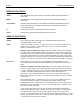
Troubleshooting guide
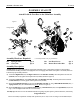

ASSEMBLY STAGE #4
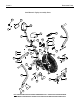
Attach Pivot Arms to the Main Base
Assembly Hardware Required:
#23 Spring Washer Qty. 2 #30 Pivot Bolt M8 Qty. 2
#24 Acorn Nut M8 Qty. 2 #31 Flat Washer Qty. 2
Assembly Description:
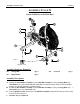
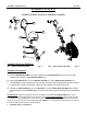
A) Install the Pivot Arms (#16 & #17) by threading the (preinstalled) pivot shaft into the corresponding pivot-boss of
the Base Frame Assembly (#1). Using a standard crescent wrench (not included), thread each shaft into the pivot
-boss using a clockwise rotation. Fully tighten each shaft until it is flush against the pivot-boss of the Base Frame
Assembly. (Reference Figure #3)
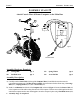
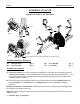
B) Once the Pivot Arms are mounted to the Base Frame Assembly, attach the ends of the Connecting Arms (#15)
using 1-Pivot Bolt (#30), 1-Flat Washer (#31), 1-Spring Washer (#23), and 1-Acorn Nut (#24) per side.
(Figure #4).
Hardware Orientation:The #31-Flat Washer must be placed in-between the connecting arm and inner flange mount-
ing of the Pivot Arm. (Reference Figure #4).
Safety Note: The arm / pedal movement can be locked in place by turning the Fan Safety Knob until it makes contact
with
the fan wheel..
Assembly Stage #4 completed.
A
SSEMBLY INSTRUCTION PAGE 7
Figure 3
Figure 4
Place #31 Flat Washer in-between the Connecting Arm and the Pivot Arm
30
24
23
17
16
Pivot Shaft
Pivot-Boss
30
31
23
24
Fan Safety Knob