Use, Care, and Installation Guide www.zephyronline.com Okeanito COK-E36BSX COK-E42BSX COK-E48BSX Model number: Serial Number: Date of Purchase: Sales Dealer: JAN13.
www.zephyronline.
INSTALLATION Ducting Calculation Sheet ....................................... Mounting Height & Clearance................................ Ducting Options ........................................................... Hood Specifications ................................................... Preparing the Electrical Wires ............................... Internal Blower ............................................................. Remote Blower Preparation ...................................
www.zephyronline.com Important Safety Notice READ AND SAVE THESE INSTRUCTIONS WARNING TO REDUCE THE RISK OF FIRE OR ELECTRIC SHOCK, DO NOT USE THIS FAN WITH ANY SOLID-STATE CONTROL DEVICE. WARNING TO REDUCE THE RISK OF FIRE, ELECTRIC SHOCK, OR INJURY TO PERSONS, OBSERVE THE FOLLOWING: a. Use this unit only in the manner intended by the manufacturer, if you have questions, contact the manufacturer. b.
TO REDUCE THE RISK OF FIRE, USE ONLY METAL DUCTWORK. NOT FOR USE IN OUTDOOR COOKING ENVIRONMENTS. CAUTION To reduce risk of fire and to properly exhaust air outside - Do not vent exhaust air into spaces within walls, ceilings, attics, crawl spaces or garages. OPERATION Always leave safety grilles and filters in place. Without these components, operating blowers could catch onto hair, fingers and loose clothing.
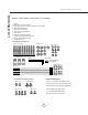
List of Materials www.zephyronline.
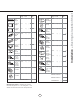
Equivalent number length x used = Duct pieces Total Total 3-1/ 4” x 10” 1 Ft. Rect., straight x( ) = Ft. 6”- 8” Round 30 Ft. wall cap with damper x( ) = Ft. 7” Round, straight 1 Ft. x( ) = Ft. 6”- 8” Round, 30 Ft. roof cap x( ) = Ft. 8” Round, straight 1 Ft. x( ) = Ft. 6” round to 1 Ft. 3-1/ 4” x 10” rect. transition x( ) = Ft. 3-1/ 4” x 10” 15 Ft. Rect. 90 0 elbow x( ) = Ft. x( ) = Ft. 3-1/ 4” x 10” 9 Ft. Rect. 45 0 elbow x( ) = Ft. 6” round to 16 Ft.
Installation – Mounting Height & Clearance www.zephyronline.com If turns or transitions are required; install as far away from opening and as far apart, between 2, as possible. Minimum mount height between range top and hood bottom should be no less than 28”. A n. mi . B x ma C n. mi . D x ma Maximum mount height should be no higher than 36”. It is important to install the hood at the proper mounting height.
NEVER exhaust air or terminate duct work into spaces between walls, crawl spaces, ceiling, attics or garages. All exhaust must be ducted to the outside. Use metal ductwork only. Fasten all connections with sheet metal screws and tape all joints with certified Silver Tape or Duct Tape.
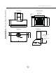
” Bottom View (36”) 5” (42“) 8” (48“) 3-1/2” 19-3/4” 19-3/4” Front View (36”) 26-1/16” (42“) 26-1/16” (48“) 41” 14-1/2” 21” 36”, 42”, 48” Side View 10” Standard Duct Cover min. : 30-1/2” max. : 49-1/2” 13-1/2” duct cover 6” C/L 5-1/8” 8” collar C/L Top View 4-1/4” 6” collar C/L Installation – Hood Specifications www.zephyronline.com 95 22-3/4” 8 ° Z1C-00OK Extension min. : 44” max.
WARNING All Electrical work must by performed by qualified electrician or person with similar technical know how and background. For personal safety, remove house fuse or open circuit breaker before beginning installation. Do not use extension cord or adapter plug with this appliance. Follow national electrical codes or prevailing local codes and ordinances.
Installation – Internal Blower www.zephyronline.com INTERNAL BLOWER PREPARATION 1. Position internal blower inside hood body so internal blower collar proturdes though 6” round flange opening. 2. Secure internal blower to internal blower flange by (4) M4*16 screws from internal blower hardware. 3. Position capacitor box inside hood body and secure by (2) M4*8 screws from internal blower hardware. 4. Secure ground wire from capacitor box to ground wire rivet nut next to capacitor box. 5.
1. Remove internal blower flange plate. 2. Install remote blower 8” round collar. Attach by (4) M4*8 screws. 3. Install threaded cable lock and remote blower wiring harness through the remote blower wiring knockout. Attach by (4) M4*8 screws. 4. Secure ground wire from remote blower wiring to ground wire rivet nut. NOTE: For instructions on mounting the remote blower please refer to the CBE-1000 or PBN1000A remote blower manual included in the remote blower packaging or on our website at www.
Installation – Mounting the Range Hood www.zephyronline.com ! CAUTION: At least two installers are required due to the weight and size of the hood. C 8-1 1/1 6” C/L C/L B 6” 14-1/2” 9-11/16” A FIG. 2 Top gap between bracket and wall min. 28” max. 36” C/L Bottom FIG. 1 FIG. 3 1. Measure from cooking surface to desired hood bottom, level and mark line A. (28” minumum from cooking surface) 2. Plum and mark center line. 3. Mark line B, 9-11/16” up from line A.
11. Lift hood onto wall bracket. The lip at the back of the hood body will rest between the wall and the top lip of the wall bracket. Secure hood body in place by (2) M4*1-1/2” screws though bottom section of interior of hood body. FIG. 4 12. Place telescopic duct covers on top of hood. 13. Run duct work from ceiling to motor collar and seal all joints with certified aluminum duct tape. 14. Install electrical wiring. FIG. 5 15. Attach upper (inner) duct cover to ceiling bracket by (2) M4*8 screws. FIG. 4 16.
Features & Controls – Touch Controls www.zephyronline.com 5 Display 1 Blower On/Off (Speed level, Delay Off Indicator) 3 15 Min Delay Off 6 Mood Light On/Off 2 Adjust 3 Speed Levels 4 Lights On/Dim/Off 1 Blower On/Off By pressing , the blower is switched On and Off. When switched on, the blower and lights turn on at the same setting they were switched off at. When switched off the entire hood powers off, including the LED and Mood lights.
Baffle Filter Clean Indicator When F flashes on display, the baffle filters installed are required to be cleaned. This will occur after every 30 hours of use. Clean Filters display < F > flashes F Re-setting Function Reset the filter clean reminder timer when filters are cleaned and re-installed (with hood off). Press and hold for approximately 5 seconds, the display will appear; hold for approximately 5 seconds until F on display disappears .
Maintenance – Cleaning and Installing Filters www.zephyronline.com SURFACE MAINTENANCE: Clean periodically with hot soapy water and clean cotton cloth. Do not use corrosive or abrasive detergent, or steel wool/scoring pads which will scratch and damage surface. For heavier soil use liquid degreaser. After cleaning, you may use non-abrasive stainless steel polish/ cleaners, to polish and buff out the stainless luster and grain.
Issue Cause What to do After installation, the unit doesn’t work. 1. The power source is not turned ON. 1. Make sure the circuit breaker and the unit’s power is ON. 2. The power line and the cable locking connector is not connecting properly. 2. Check the power connection with the unit is connected properly. 3. The switch board and control board wirings are disconnected. 3. Make sure the wirings between the switch board and control board are connected properly. 4.
Wiring Diagrams www.zephyronline.
19 Wiring Diagrams
List of Parts and Accessories www.zephyronline.com DESCRIPTION PART # Replacement Parts Light Bulb 6W LED (each) Z0B-0035 Baffle Filter (each) 50210019 Optional Accessories Duct Cover Extension Z1C-00OK Single Internal Blower CBI-290A / CBI-600A External Blower CBE-1000 In-Line Blower PBN-1000A To order parts, please visit us online at http://store.zephyronline.com or call us at 1.888.880.
STAPLE YOUR RECEIPT HERE Proof of the original purchase date is needed to obtain service under warranty Limited Warranty TO OBTAIN SERVICE UNDER WARRANTY OR FOR ANY SERVICE RELATED QUESTIONS, please call: 1-888-880-8368 Zephyr Corporation (referred to herein as “we” or “us”) warrants to the original consumer purchaser (referred to herein as “you” or “your”) of Zephyr products (the “Products”) that such Products will be free from defects in materials or workmanship as follows: Three Year Limited Warranty