Padova CPA - E42ASX CPA - E48ASX CPA - E54ASX Guide d’utilisation, d’entretien et d’installation Guía de instalación, uso y mantenimiento Use, Care, and Installation Guide www.zephyronline.
English French page page 2 28 Spanish page 56 APPROVED FOR RESIDENTIAL APPLIANCES FOR RESIDENTIAL USE ONLY READ AND SAVE THESE INSTRUCTIONS PLEASE READ ENTIRE INSTRUCTIONS BEFORE PROCEEDING. INSTALLATION MUST COMPLY WITH ALL LOCAL CODES. IMPORTANT: Save these Instructions for the Local Electrical Inspector’s use. INSTALLER: Please leave these Instructions with this unit for the owner. OWNER: Please retain these instructions for future reference.
Important Safety Notice .................................................................... 5 Electrical & Installation Requirements ............................................ 6 Electrical requirements .............................................................. 6 Before installing the hood ........................................................... 6 List of Materials ................................................................................. 7 Parts supplied ....................................
Table of Contents Installation - Installing the Duct Covers ......................................... 18 Installation - Hanging the Hood onto the Wall .............................. 19 Installation - Electrical Connection & Final Installation Steps ..... 20 Electrical connection ................................................................ 20 Description of the Hood .................................................................. 21 Features & Controls - Touch Controls & Features .....................
READ AND SAVE THESE INSTRUCTIONS CAUTION FOR GENERAL VENTILATING USE ONLY. DO NOT USE TO EXHAUST HAZARDOUS OR EXPLOSIVE MATERIALS OR VAPORS. WARNING TO REDUCE THE RISK OF FIRE, ELECTRIC SHOCK, OR INJURY TO PERSONS, OBSERVE THE FOLLOWING: A. Use this unit only in the manner intended by the manufacturer. If you have questions, contact the manufacturer. B.
Electrical & Installation Requirements ELECTRICAL REQUIREMENTS IMPORTANT Observe all governing codes and ordinances. It is the customer’s responsibility: To contact a qualified electrical installer. To assure that the electrical installation is adequate and in conformance with National Electrical Code, ANSI/NFPA 70 — latest edition*, or CSA Standards C22.1-94, Canadian Electrical Code, Part 1 and C22.2 No.0-M91 - latest edition** and all local codes and ordinances.
PARTS SUPPLIED • • • • • • • • • • • • Hood body, with stainless steel baffle filter and halogen light bulbs and incandescent lamp already installed Two telescopic duct covers and support bracket Hardware Packet: - 24x53 T1T2 "L" Male monkey spanner (1 piece) - 3.5X9.5 screws to fix the internal blower (4 pieces) - 3.5X9.5 screws to fix the duct cover (4 pieces) - 3.5X9.
3-15/32" - (42") 3-55/64" - (48") 4-17/32" - (54") 8-35/64" - (42") 9-53/64" - (48") 11-1/32" - (54") min 28-1/2" 18" max 35" 1" 11/16 3-1/2" 41-15/16", 48", 54" 23" 5/8 24" 1/2 Ø 9" 7/16 6" 7/16 ceiling 11" Ducting and conduit area passage(Duct bends are not considered) 38", 44", 50" /8 ø7 1" 15/16 Dimensions and Clearances 15" 29" * Side Cabinet 1" ø1 5/1 1/2" 6 6" 11/16 23" ** KNOCK-OUT EXTERNAL BLOWER CONNECTION Side Cabinet 41-15/16", 48", 54" 1/2" min.
Closely follow the instructions set out in this manual. All responsibility, for any eventual inconveniences, damages or fires caused by not complying with the instructions in this manual, is declined. VENTING METHODS This range hood is designed to exhaust fumes and vapours towards the outside and is ready to be fitted with an internal blower and for discharge towards the top side (Vertical discharge).
Installation - Ductwork Calculation Sheet Duct pieces Equivalent number lenght x used = Duct pieces Equivalent number lenght x used = Total Total 3 1/4 ” x 10” Rect., straight 1 Ft. x( )= Ft. 6" Round 30 Ft. wall cap with damper x( )= Ft. 6 ” Round,, straight 1 Ft. x( )= Ft. 6” Round, roof cap 30 Ft. x( )= Ft. 7", 8” Round,, straight 1 Ft. x( )= Ft. 6” Round to 3 1/4 ” x 10” rect. transition 1 Ft. x( )= Ft. 3 1/4 ” x 10” Rect.90° elbow 15 Ft. x( )= Ft. 16 Ft.
Installation - Preliminary Operations www.zephyronline.com Attention! The installation requires several steps where is asked to temporarily remove some particulars and screws, We recommend to record and keep all of these components in a safe place ready to be used as required. • Remove stainless mesh filters (See relative paragraph on Maintenance section of this manual). • Release the 4 per side threaded knobs and remove the internal left-right side covers.
Installation - Internal Blower Note: for External blower installation disregard the instruction in this page and step ahead on page 14. • Install the motor support to the body of the hood (Rear side) with 4 screws in place of the rear cover previously removed. Note! Lip of motor support must be towards the inside of the hood in order for screw holes to line up.
INTERNAL BLOWER INSTALLATION • Fit the blower inside the hood. • Install the blower to the support with 4 screws (Provided), check that the rectangular outlet of the blower matches with the rectangular slot of the support. Note: The 4 fixing screws must be screwed in from the outside of the hood (See photo below). • 13 Connect the blower to the range hood. Installation - Internal Blower www.zephyronline.
Installation - External Blower Preparation Note: for internal blower installation, disregard the instruction on this next page and consult the instruction on the previous pages (See pages 12-13). Note 2: Refer to the CBE-1000 manual for instructions on mounting the external blower to a roof or exterior wall. The manual is available on our website and is included in the external blower packaging.
• Install the supplied round transition collar to the previously installed cover/round transition support plate. Align and attach with 2 screws securely. • Install the external blower junction box with 4 screws. • Connect the supplied 9 pin male molex plug from the external blower wiring to the 9 pin female molex plug on the control board housing. Route wire end through hood and terminate in external blower junction box. See diagram below.
Installation - Front Panel • To attach front panel to hood body, align the 8 threaded studs through the front bodies corresponding holes. Use 8 wing nuts to attach and secure. See diagrams below 4 3 2 1 1 3 4 4 3 2 6 5 5 8 6 7 7 8 x8 NOTE: The front panel is not supplied with the range hood and must be purchased separately.
INSTALLING THE HOOD ONTO THE WALL 1. Disconnect and move freestanding or slide-in range from cabinet opening to provide easier access to rear wall. Use a thick, protective covering over countertop, cooktop or range to protect from damage and debris. Select a flat surface for assembling the unit. Cover that surface with a protective covering and place all canopy hood parts and hardware in it. Framing behind drywall 2. Mark the centerline on the wall/ceiling where the canopy hood will be installed.
Installation - Installing the Duct Covers 13. Optional duct cover installation: Unscrew the 4 screws that fix the section of the Duct Cover (Starting collar) and release all parts. Install the upper section to the support bracket with 2 screws. Note: Check that joined seam is positioned towards the back. Note2: The lower section (Collar) of the duct cover assembly must be installed at the end of the installation with 2 screws. Support Bracket Upper section Lower section (Collar) a.
14. For internal blower installation ONLY: a. Horizontal (Rear) discharge: Install from the outside the 3 1/4 ” x 10” Rect. transition on the outlet hole of the blower with 3 screws. b. Vertical (Upper) discharge: Install from the outside the 8" plastic round transition, with 4 screws. Install transition so that little position adjustment are allowed. Note: Seal with duct tape only when transition is firmly attached to the range hood.
Installation - Electrical Connection & Final Installation Steps 18. Electrical connection 19. Note: disregard this step if the hood has been fitted with an internal blower. Purchase and install an External blower (See paragraph „Before installing the hood - Parts not supplied“ for model reference). WARNING Electrical Shock Hazard Warning: Turn off power circuit at the service panel before wiring this unit. 120 VAC, 15 or 20 Amp circuit required. 20.
1 2 3 4 5 6 Controls Baffle filter Halogen lamp Incandescent ambient lamp Hood body Duct cover 6 4 5 3 2 2 3 1 21 Description of the Hood www.zephyronline.
Features & Controls - Touch Controls & Features Use the high suction speed in cases of concentrated kitchen vapors. It is recommended that the cooker hood suction is switched on for 5 minutes prior to cooking and to leave in operation during cooking and for another 15 minutes after terminating cooking. Note: Hood retains last speed setting when aspiration switch is turned off.
Filter Clean Reminder (Standard Baffle Filters fitted): A set of baffle filters are fitted by the factory. These Baffle Filters are intended to filter out residue from cooking. They need not be replaced on a regular basis but are required to be kept clean. The Filter Clean Reminder function in the microprocessor will automatically indicate by a flashing when the metal filters need to be cleaned after every 30 hrs. of use. Filters can be cleaned by hand with non-abrasive soap or in a dishwasher.
Maintenance ATTENTION! Prior to any maintenance operation ensure that the cooker hood is disconnected from the power supply. CLEANING The cooker hood should be cleaned regularly internally and externally. Use a cloth moistened with a neutral liquid detergents. Avoid abrasive detergents. Warning: Failure to carry out the basic cleaning recommendations of the cooker hood and replacement of the filters may cause fire risks. Therefore, we recommend oserving these instructions.
Maintenance www.zephyronline.com REPLACING THE MOOD LIGHTING BULB: To replace mood lighting bulb, remove baffle filter from hood. To access lamp area, remove the two threaded knobs that fix the cover. Unscrew mood lighting bulb counter-clockwise and replace with a standard max. 40W, type T10, 125V-130V medium base bulb.
Trouble Shooting Issue After installation, the unit doesn’t work? Light works, but motor is not turning. The unit is vibrating. The motor is working, but the lights are not. The hood is not venting out properly. Metal filter is vibrating. Cause What to do 1. The power source is not turned ON. 1. Make sure the circuit breaker and the unit’s power is ON. 2. The power line and the cable locking connector is not connecting properly. 2. Check the power connection with the unit is connected properly.
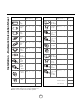
Part Description Part# Halogen Bulb, 120V 50 W Z0B0020S Filter Baffle 50210002 Part Description Part# Internal Blower 600 CFM EBI-600B External Blower 1000 CFM CBE-1000 Front Panel 42" SS CPC-0012 Front Panel 42" Brass CPC-0112 Front Panel 48" SS CPC-0018 Front Panel 48" Brass CPC-0118 Front Panel 54" SS CPC-0015 Front Panel 54" Brass CPC-0115 Doluflex 6pc. Blank, 42" CDO-0042 Doluflex 6pc. Blank, 48" CDO-0048 Doluflex 6pc. Blank, 54" CDO-0054 Veneer, 6pc.