Use, Care, and Installation Guide www.zephyronline.com Trapeze CTP-E 48SX CTP-E54SX CTP-E 60SX Model number: Serial number: Date of Purchase: Sales Dealer: MAY07.0101 © Zephyr Corporation.
www.zephyronline.
2 3 INSTALLATION Ducting Calculation Sheet ............................... Mounting Height and Clearance ..................... Ducting .................................................................. Specifications ....................................................... Internal Blower .................................................... Preparing Hood for External Blower .............. Mounting the Hood ............................................
www.zephyronline.com Important safety Notice READ AND SAVE THESE INSTRUCTIONS WARNING TO REDUCE TH E R IS K O F FIR E O R E LE C TR IC SHOC K, DO NOT USE TH IS FAN W ITH ANY S O LID-S TATE SPE E D CONTROL DEV IC E. WARNING TO RE DUCE TH E R IS K O F FIR E, E LE C TR IC SH O C K, O R INJU RY TO P E R SON S, O B S E RVE TH E FO LLO W ING: a. Use this unit only in the manner intended by the manufacturer, If you have questions, contact the manufacturer. b.
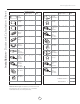
1 2 4 2 2 4 4 4 1 1 1 - Lis t of M a teria ls MODEL: CTP-ExxS Hood Baffle Filters G U-10, 120V 50 W, halogen bulbs Utensil Rails Telescopic Duct Covers Telescopic Rods Sets Angle Bra ckets (27 3/8”) Angle Bra ckets (35 3/8”) Ceiling MountingBra cket Internal Flange Motor Housing 1 - HARDWARE PACKET 4 - Couplers 4 - Anchors 4 - 2” Wood Screws 4 - 2 1/2” Wood Screws 4 - 1/2” Washers 26 - 1/2” Self Tapping Screws 4 - 1/2” Screws 5x15mm 4 - 5mm Internal Diameter Washers 4 - Adhesive Fasteners 4 - Cable Ties
Ins ta lla tion - Ductwork C a lcula tion S heet www.zephyronline.com Equivalent number length x used = Duct pieces Equivalent number length x used = Duct pieces Total Total 3 1/4” x 10” Rect., straight 1 Ft. x( ) = Ft. 6” Round 30 Ft. wall cap with damper x( ) = Ft. 7” Round, straight 1 Ft. x( ) = Ft. 6” Round, roof cap 30 Ft. x( ) = Ft. 7” Round, straight 1 Ft. x( ) = Ft. 6” round to 3 1/4” x 10” rect. transition 1 Ft. x( ) = Ft. 3 1/4” x 10” Rect. 90 0 elbow 15 Ft.
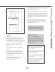
Maximum mount height should be no higher than 36". Min 34"-Max 52" 9" Min 28"-Max 36" Min 98"-Max 124” It is importantto install the hood at the proper mounting height. Hoods mountedtoo low could result in heat damage and fire hazard; while hoods mountedtoo high will be hard to reach and will loose its performance and efficiency. If available, also refer to range manufacturer's height clearance requirements and recommended hood mountingheight above range.
Ins ta lla tion - Ducting www.zephyronline.com WARNING FIRE HAZARD NEV E R exhaust air or terminate duct work into spaces between walls, crawl spaces, ceiling,attics or garages. All exhaust must be ducted to the outside. Use single wall rigid Metal ductwork only. Fasten all connections with sheet metal screws and tape all joints w/ certified Silver Tape or DuctTape.
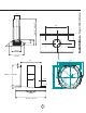
“ 15 3/4” 26 5/8” 11 3/4“ 10“ 9“ 32” 10 7/16” 9 1/2” R Min 21” - Max 40” 7/64” 12 1/8” 13/32” 2” 48” , 54” , 59 1/8” 7 41 /8 6 21/ 10 O 13 /8 ” ” 4” 15/32” 2” Installation - Specifications 32“ 9“ 6“ Min 34“ - Max 52” 9“
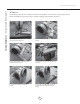
Ins ta lla tion - Interna l B lower www.zephyronline.com ATTENTION The following are intructions for installing internal blower model CBI-600. For instructions on preparing for external blower model CBE-1000 please turn to page “10”. Before installing, verify that motor spins freely. The internal blower kit consists of the blower and capacitor box with wiring. 1. Remove existing screws from blower housing. 2. Att ach capacitor box to blower housing using the removed screws. 3.
7. Attach grounding wires from junction box and motor to grounding screw as shown. 8. Place blower with attached flange into motor housing as shown on Fig-A. 9. Attach using 1/2” self tapping screws to secure in place. 10. Att ach other end of capacitor box connector and junction box connector to control board box and wiring box connector inside hood. Continue to page “11” for hood installation instructions. For external blower installation please refer to the manual included with the external blower.
Ins ta lla tion - P repa ring Hood for E xterna l B lower www.zephyronline.com ATTENTION The following are instructions on preparing your hood for installation with external blower model CBE-1000. For instructions on installing internal blower model CBI-600 please turn to page “8”. The external blower kit consists of an 8” collar, external flange and external blower wiring box. The external blower is purchased separately. 1.
CL Mounting Holes Marking for Coupler CL Narrow End Tabs Add Blockings Tabs Ceiling Bracket 1. Using the cardboard template from top of box, mark the center point in between the (4) mounting holes. Determine the location for mounting your hood, place template on ceiling and mark/drill the center point for the ceiling mounting bracket and the foud corner holes where the telescopic rod couplers will attach to the ceiling. 2. Cut out hole for the duct work. 3.
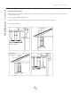
Ins ta lla tion - M ounting the Hood www.zephyronline.com 1. Mount motor housing to the range hood body using (10) 1/2” self tapping screws. 2. Determine height of hood, measure and select either 27 3/8” or 35 3/8” angle brac kets and attach (4) of them to the motor housing using (8) 1/2” self tapping screws (2) for each angle bracket. 3. Slide duct covers over motor housing. Make sure bottom duct cover with cut-out is facing the front and back of the hood.
[a] Ductwork Electrical wiring [b] 5. Lift assembled unit and attach all (4) angle brackets to ceiling bracket. Make sure the tabs on each angle brackets are facing the outside. The angle brackets will fit between the slots on the ceiling bracket. One half of the angle bracket will be on the outside of the ceiling bracket and the other half will be on the inside of the ceiling bracket. Attach using provided1/2” self tapping screws. Re fer to diagram [a]. 6.
Ins ta lla tion - M ounting the Hood www.zephyronline.com Telescopic Rod Installation Set screws 1. Install telescopic rod (thicker end down) into coupler on top of hood and secure with medium set screw. Attach screw using provided tool. 2. Extend telescopic rod towards the ceiling and insert thin end of rod into ceiling coupler. Attach a medium set screw in the middle where the two rods attach to each other. 3. Attach medium set screw into the ceiling coupler to secure it in place.
Fea tures & C ontrols - Touch C ontrols & F ea tures www.zephyronline.com 1. Blower On/Off By pressing , the blower is switched On and Off. 2. Speed Selection The 3 speed levels are selected by presing level selected. to decrease and to increase speed level. T he display indicates 3. Delay Off This is used for programmed shut down of blower and lights 15 minutes after the function is activated. Press once, a dot flashes in the lower right hand side of display indicating the function is on.
Filter Clean Reminder: When flashes on display, the baffle filters installed are required to be cleaned. This will occur after every 30 hours of use. Clean Filters display flashes Re-setting Function: Reset the Filter Clean Reminder timer when filters are cleaned and re-installed (with hood off). Press and hold for approx. 5 seconds, the display will appear; hold for approximately 5 seconds until on display disappears .
M a int ena nce - C le aning www.zephyronline.com Surface Maintenance: Clean periodically with hot soapy water and clean cotton cloth. Do not use corrosive or abrasive detergent , or steel wool/scouring pads which will scratch and damage surface. For heavier soil use liquid degreaser. After cleaning, you may use non-abrasive stainless steel polish/ cleaners, to polish and buff out the stainless luster and grain. Always scrub lightly, with clean cotton cloth, and with the grain.
CAUTION: Light bulbs become extremely hot when turned on. DO NOT touch bulbs until switched off and cooled. Touching hot bulbs may cause serious burns. Make sure all power is turned off and bulbs are not hot. Remove bulb by pressing both ends of the metal retaining clip together, the light socket will now extend from the hood allowing you to remove the bulb.
Trouble S hooting www.zephyronline.com Issue Cause What to do After installation, the unit doesn’t work? 1. The power source is not turned ON. 1. Make sure the circuit breaker and the unit’s power is ON. 2. The power line and the cable locking connector is not connecting properly. 2. Check the power connection with the unit is connected properly. 3. The switch board and control board wirings are disconnected. 3.
www.zephyronline.
Warranty www.zephyronline.com TO OBTAIN SERVICE UNDER WARRANTY or any Service Related Questions, please call: 1-888-880-8368 Staple your receipt here. Proof of the original purchase date is needed to obtain service under the warranty. TO OBTAIN SERVICE UNDER WARRANTY: You must present proof of original purchase date. Please keep a copy of your dated proof of purchase (sales slip) in order to obtain service under warranty.