Use, Care, and Installation Guide www.zephyronline.com Trapeze CTP-E48BSX CTP-E54BSX CTP-E60BSX Model number: Serial Number: Date of Purchase: Sales Dealer: JAN14.
www.zephyronline.
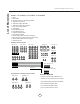
INSTALLATION Ducting Calculation Sheet ....................................... Mounting Height & Clearance................................ Ducting Options ........................................................... Hood Specifications ................................................... Blower Preparation ..................................................... Mounting the Range Hood ...................................... 5 6 7 8 9-11 12-14 FEATURES & CONTROLS Touch Controls .................................
www.zephyronline.com Important Safety Notice READ AND SAVE THESE INSTRUCTIONS WARNING TO REDUCE THE RISK OF FIRE OR ELECTRIC SHOCK, DO NOT USE THIS FAN WITH ANY SOLID-STATE CONTROL DEVICE. WARNING TO REDUCE THE RISK OF FIRE, ELECTRIC SHOCK, OR INJURY TO PERSONS, OBSERVE THE FOLLOWING: a. Use this unit only in the manner intended by the manufacturer, if you have questions, contact the manufacturer. b.
TO REDUCE THE RISK OF FIRE, USE ONLY METAL DUCTWORK. NOT FOR USE IN OUTDOOR COOKING ENVIRONMENTS. CAUTION To reduce risk of fire and to properly exhaust air outside - Do not vent exhaust air into spaces within walls, ceilings, attics, crawl spaces or garages. OPERATION Always leave safety grilles and filters in place. Without these components, operating blowers could catch onto hair, fingers and loose clothing.
List of Materials www.zephyronline.
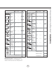
Equivalent number length x used = Duct pieces Total Total 3-1/ 4” x 10” 1 Ft. Rect., straight x( ) = Ft. 6”- 8” Round 30 Ft. wall cap with damper x( ) = Ft. 7” Round, straight 1 Ft. x( ) = Ft. 6”- 8” Round, 30 Ft. roof cap x( ) = Ft. 8” Round, straight 1 Ft. x( ) = Ft. 6” round to 1 Ft. 3-1/ 4” x 10” rect. transition x( ) = Ft. 3-1/ 4” x 10” 15 Ft. Rect. 90 0 elbow x( ) = Ft. x( ) = Ft. 3-1/ 4” x 10” 9 Ft. Rect. 45 0 elbow x( ) = Ft. 6” round to 16 Ft.
Installation – Mounting Height & Clearance www.zephyronline.com long reducer instead of a pancake reducer. Reduce duct size as far away from opening as possible. n. mi If turns or transitions are required; install as far away from opening and as far apart, between 2, as possible. A Minimum mount height between range top and hood bottom should be no less than 26”. x. B ma n. mi C Maximum mount height should be no higher than 36”. x. D in. ” m x.
NEVER exhaust air or terminate duct work into spaces between walls, crawl spaces, ceiling, attics or garages. All exhaust must be ducted to the outside. Use metal ductwork only. Fasten all connections with sheet metal screws and tape all joints with certified Silver Tape or Duct Tape.
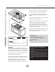
Top View Side View 32” 6-13/16” Z1C-00TP Extension Min 47” - Max 72” 15-3/4” Ceiling Bracket 11-3/4” 10” 9” 13/16” 3-1/8” 5/8” 9-1/2” 12-1/8” 10-7/16” 1/2” 8-15/16” Min 21-5/8” Max 41” 2-3/8” Front View 1- 3/ 8” FRONT 47-15/16”, 53-15/16”, 59-1/8” 8 26-7/8” 8-7/8” 25-3/16” Standard Duct Cover Min 34” - Max 51 1/2” 2-1/8” 6-9/16” Installation – Hood Specifications www.zephyronline.
1. Remove internal blower flange from motor housing by (6) screws. 2. Secure internal blower to internal blower flange by (4) M4*16 screws from internal blower hardware. 3. Secure AC power wiring box to internal blower flange by (2) M4*8 screws. 4. Secure ground wire to underside of internal blower flange by (1) 3/16*3/8 screw and (1) washer. 5. Connect 9 pin molex connector from capacitor cable to 9 pin molex connector from internal blower. 6.
Installation – Blower Preparation www.zephyronline.com INTERNAL BLOWER PREPARATION CONT. 8. Connect 6 pin molex connector from capacitor cable to 6 pin molex connector from control box. Connect 2 pin plug from AC power cable to 2 pin plug from control box. Secure cables to hood interior with zip ties and zip tie holders. 7. Secure motor housing to hood body by (12) M4*6 screws. 9. Secure capacitor box to internal hood body by (2) M4*8 screws and secure ground wire by (1) 3/16*3/8 screws.
3. Secure AC power ground wire and remote blower ground wire to underside of remote blower flange by (1) 3/16*3/8 screw and (1) washer each. 4. Secure remote blower 8” round collar to remote blower flange by (8) M4*8 screws. 5. Secure remote blower flange to motor housing using (6) screws previously removed from step 1. 6. Secure motor housing to hood body by (12) M4*6 screws.
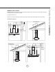
Installation – Mounting the Range Hood www.zephyronline.com Tabs Add Blockings Tabs FIG. 1 Ceiling Bracket Ceiling CL Mounting Holes Marking for Coupler CL Set screw mounting hole FRONT FIG. 2 Electrical wiring passage 1. Determine the location for mounting the hood. Mark centerlines front to back and left to right of hood placement. Place supplied paper template on ceiling and center marked center lines with template center lines.
A B A B A A B A FIG. 4 B FIG. 3 7. Determine desired height of hood, measure and select either 27 3/8” or 35 3/8” angle brackets. Position and attach angle brackets type A and B to the motor housing as shown using (8) M4*6 screws, (4) for each angle bracket. FIG. 3. 8. Slide duct covers over motor housing. Make sure bottom duct cover with cut-out is facing the front and back of hood. FIG. 3. 9. Lift assembled unit and attach all (4) angle brackets to ceiling bracket.
Installation – Mounting the Range Hood www.zephyronline.com Telescopic Rod Installation Set screws 1. Install telescopic rod (thicker end down) into coupler on top of hood and secure by (1) M4*4 set screw for each rod. 2. Extend inner telescopic rod to ceiling coupler and attach by (1) M4*4 set screw for each rod. 3. Secure telescopic rods together at top of outer rod by (1) M4*4 set screw for each rod set. Tool Set screw FRONT BACK Utensil Rail Installation 1.
1 Blower On/Off (Speed level, Delay Off Indicator) 3 15 Min Delay Off 2 Adjust 3 Speed Levels 4 Lights On/Dim/Off 1 Blower On/Off By pressing , the blower is switched On and Off. When switched on, the blower and lights turn on at the same setting they were switched off at. When switched off the entire hood powers off, including the LED and Mood lights. 2 Speed Selection The 3 speed levels are selected by pressing to decrease and to increase speed level. The display indicates speed level selected.
Features & Controls – Features www.zephyronline.com Baffle Filter Clean Reminder Whether your hood is installed as an exhaust or purifying unit, a set if baffle filters are fitted by the factory, These baffle filters are intended to filter out residue from cooking. They need not be replaced on a regular basis but are required to be kept clean.
SYNCHRONIZATION: To create a unique link between your hood and remote control please follow these steps: 1. With hood off, press and hold the “lights” button on the hood until the letter “F” shows on the display screen. 2. Press the “lights” button on the remote, the lights on the hood will turn on and synchronization is complete. RF REMOTE FUNCTIONS: Blower On/ Speed Selection 1 Blower On/ 2 Power Off 1 Blower On / Speed Selection Press to power on blower and cycle through all six blower speeds.
Maintenance – Cleaning and Installing Filters www.zephyronline.com SURFACE MAINTENANCE: Clean periodically with hot soapy water and clean cotton cloth. Do not use corrosive or abrasive detergent, or steel wool/scoring pads which will scratch and damage surface. For heavier soil use liquid degreaser. After cleaning, you may use non-abrasive stainless steel polish/ cleaners, to polish and buff out the stainless luster and grain.
Issue Cause What to do After installation, the unit doesn’t work. 1. The power source is not turned ON. 1. Make sure the circuit breaker and the unit’s power is ON. 2. The power line and the cable locking connector is not connecting properly. 2. Check the power connection with the unit is connected properly. 3. The switch board and control board wirings are disconnected. 3. Make sure the wirings between the switch board and control board are connected properly. 4.
Wiring Diagrams www.zephyronline.com CTP-E48/54/60BSX VOLTS HZ MAX AMPS 120 60 CBI290A 0.8 CBI600A 2.
HZ MAX AMPS 120 60 CBE1000 6.0 PBN1000A 4.
List of Parts and Accessories www.zephyronline.com DESCRIPTION PART # Replacement Parts 6W Bloom™ HD LED Light Bulbs (each) Z0B-0034 Baffle Filter (each) 50210022 Optional Accessories Duct Cover Extension Z1C-00TP Single Internal Blower CBI-290A / CBI-600A External Blower CBE-1000 In-Line Blower PBN-1000A To order parts, please visit us online at http://store.zephyronline.com or call us at 1.888.880.
STAPLE YOUR RECEIPT HERE Proof of the original purchase date is needed to obtain service under warranty Limited Warranty TO OBTAIN SERVICE UNDER WARRANTY OR FOR ANY SERVICE RELATED QUESTIONS, please call: 1-888-880-8368 Zephyr Corporation (referred to herein as “we” or “us”) warrants to the original consumer purchaser (referred to herein as “you” or “your”) of Zephyr products (the “Products”) that such Products will be free from defects in materials or workmanship as follows: Three Year Limited Warranty