8VH &DUH DQG ,QVWDOODWLRQ *XLGH WWW ZEPHYRONLINE COM 7UDSH]H #40 % 38 #40 % 38 #40 % 38 -ODEL NUMBER 3ERIAL NUMBER $ATE OF 0URCHASE 3ALES $EALER #40 2EV ¹ :EPHYR #ORPORATION
www.zephyronline.
INSTALLATION Ducting Calculation Sheet ...................................................................................... Mounting Height and Clearance ....................................................................... Ducting ..................................................................................................................................... Specifications .....................................................................................................................
WWW ZEPHYRONLINE COM ,PSRUWDQW VDIHW\ 1RWLFH 5($' $1' 6$9( 7+(6( ,16758&7,216 :$51,1* 4/ 2%$5#% 4( % 2 )3 + / & &)2 % / 2 % ,% # 42 )# 3(/# + 30% % $ #/.42/, $%6 )# % $/ ./4 53% 4( )3 &!. 7 )4( !.9 3 / ,)$ 3 4!4% :$51,1* 4/ 2% $5#% 4( % 2 )3 + / & &)2 % % ,% # 42 )# 3( / # + / 2 ).*5 29 4/ 0 % 2 3/. 3 / " 3 % 26% 4( % &/ ,,/ 7 ).
\Ê /* ÝÝ- ,IST OF -ATERIALS " (OOD "AFFLE &ILTERS '5 6 7 HALOGEN BULBS 5TENSIL 2AILS 4ELESCOPIC $UCT #OVERS 4ELESCOPIC 2ODS 3ETS !NGLE "RACKETS v !NGLE "RACKETS v #EILING -OUNTING "RACKET )NTERNAL &LANGE -OTOR (OUSING (!2$7!2% 0!#+%4 #OUPLERS !NCHORS v 7OOD 3CREWS v 7OOD 3CREWS v 7ASHERS v 3ELF 4APPING 3CREWS v 3CREWS X MM MM )NTERNAL $IAMETER 7ASHERS !DHESIVE &ASTENERS #ABLE 4IES 3-!,, (!2$7!2% 0!#+%4 3HORT 3
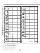
Installation - Ductwork Calculation Sheet www.zephyronline.com Equivalent number length x used = Duct pieces Equivalent number length x used = Duct pieces Total Total 3 1/4” x 10” 1 Ft. Rect., straight x( ) = Ft. 6” Round wall cap with damper 30 Ft. x( ) = Ft. 7” Round, straight 1 Ft. x( ) = Ft. 6” Round, roof cap 30 Ft. x( ) = Ft. 7” Round, straight 1 Ft. x( ) = Ft. 6” round to 1 Ft. 3 1/4” x 10” rect. transition x( ) = Ft. 3 1/4” x 10” 15 Ft. Rect.
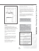
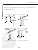
-AXIMUM MOUNT HEIGHT SHOULD BE NO HIGHER THAN -IN -AX -IN -AX -IN -AX v )T IS IMPORTANTTO INSTALL THE HOOD AT THE PROPER MOUNTING HEIGHT (OODS MOUNTEDTOO LOW COULD RESULT IN HEAT DAMAGE AND FIRE HAZARD WHILE HOODS MOUNTEDTOO HIGH WILL BE HARD TO REACH AND WILL LOOSE ITS PERFORMANCE AND EFFICIENCY )F AVAILABLE ALSO REFER TO RANGE MANUFACTURERgS HEIGHT CLEARANCE REQUIREMENTS AND RECOMMENDED HOOD MOUNTINGHEIGHT ABOVE RANGE !LWAYS CHECK YOUR LOCAL CODES FOR ANY DIFFERENCES
)NSTALLATION $UCTING WWW ZEPHYRONLINE COM 7!2.).' &)2% (!:!2$ .
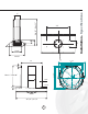
h v v ³ ³ ³ v v v 2 -IN v -AX v v v v v v v v v v / v v v ,QVWDOODWLRQ 6SHFLILFDWLRQV h h h -IN h -AX v h
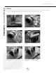
Installation - Internal Blower www.zephyronline.com ATTENTION The following are intructions for installing internal blower model CBI-600. For instructions on preparing for external blower model CBE-1000 please turn to page “10”. Before installing, verify that motor spins freely. The internal blower kit consists of the blower and capacitor box with wiring. 1. Remove existing screws from blower housing. 2. Attach capacitor box to blower housing using the removed screws. 3.
7. Attach grounding wires from junction box and motor to grounding screw as shown. 8. Place blower with attached flange into motor housing as shown on Fig-A. 9. Attach using 1/2” self tapping screws to secure in place. 10. Attach other end of capacitor box connector and junction box connector to control board box and wiring box connector inside hood. Continue to page “11” for hood installation instructions and page “15” for external blower installation instructions.
Installation - Preparing Hood for External Blower www.zephyronline.com ATTENTION The following are instructions on preparing your hood for installation with external blower model CBE-1000. For instructions on installing internal blower model CBI-600 please turn to page “8”. The external blower kit consists of an 8” collar, external flange and external blower wiring box. The external blower is purchased separately. 1.
&/ 0RXQWLQJ +ROHV 0DUNLQJ IRU &RXSOHU &/ 1DUURZ (Q 7DEV $GG %ORFNLQJV 7DEV &HLOLQJ %UDFNHW ,QVWDOODWLRQ 0RXQWLQJ WKH +RRG &HLOLQJ 8VLQJ WKH SURYLGHG WHPSODWH PDUN WKH FHQWHU SRLQW LQ EHWZHHQ WKH PRXQWLQJ KROHV 'HWHUPLQH WKH ORFDWLRQ IRU PRXQWLQJ \RXU KRRG SODFH WHPSODWH RQ FHLOLQJ DQG PDUN GULOO WKH FHQWHU SRLQW IRU WKH FHLOLQJ PRXQWLQJ EUDFNHW DQG WKH IRXU FRUQHU KROHV ZKHUH WKH WHOHVFRSLF URG FRXSOHUV ZLOO DWWDFK WR WKH FHLOLQJ 1RWH 7HPSODWH LV ORFDWHG RQ WRS RI FDUWRQ &XW RXW
Installation - Mounting the Hood www.zephyronline.com 1. Mount motor housing to the range hood body using (10) 1/2” self tapping screws. 2. Determine height of hood, measure and select either 27 3/8” or 35 3/8” angle brackets and attach (4) of them to the motor housing using (8) 1/2” self tapping screws (2) for each angle bracket. 3. Slide duct covers over motor housing. Make sure bottom duct cover with cut-out is facing the front and back of the hood.
;A= $UCT WORK %LECTRICAL WIRING ;B= ,IFT ASSEMBLED UNIT AND ATTACH ALL ANGLE BRACKETS TO CEILING BRACKET -AKE SURE THE TABS ON EACH ANGLE BRACKETS ARE FACING THE OUTSIDE 4HE ANGLE BRACKETS WILL FIT BETWEEN THE SLOTS ON THE CEILING BRACKET /NE HALF OF THE ANGLE BRACKET WILL BE ON THE OUTSIDE OF THE CEILING BRACKET AND THE OTHER HALF WILL BE ON THE INSIDE OF THE CEILING BRACKET !TTACH USING PROVIDED v SELF TAPPING SCREWS 2EFER TO DIAGRAM ;A= 3LIDE DUCT COVERS UP AND ATTACH DUCT WORK AND
Installation - Mounting the Hood www.zephyronline.com Telescopic Rod Installation Set screws 1. Install telescopic rod (thicker end down) into coupler on top of hood and secure with medium set screw. Attach screw using provided tool. 2. Extend telescopic rod towards the ceiling and insert thin end of rod into ceiling coupler. Attach a medium set screw in the middle where the two rods attach to each other. 3. Attach medium set screw into the ceiling coupler to secure it in place.
4HE FOLLOWING INSTRUCTIONS DESCRIBE THE INSTALLATION OF THE #"% EXTERNAL BLOWER FOR USE WITH :EPHYR MODELS #40 #/+ OR #3( RANGE HOODS ONLY &IG &IG 490)#!, ).34!,,!4)/. 2//& -/5.4 %LBOW $UCT /543)$% 7!,, -/5.4 %LBOW 2OOF (OOD (OOD 2ECOMMENDED FOR USE ONLY OVER CONVENTIONAL DOMESTIC GAS AND ELECTRIC RANGES /UTSIDE 7ALL )NSTALLATION %XTERNAL "LOWER 3PECIFICATIONS .
Installation - External Blower www.zephyronline.com 1. Remove and discard shipping brackets and wood support (attached to sides of motor and inlet collar). Fig. - 7 BEFORE INSTALLING, check to see if blower wheel turns freely and does not rub on motor brackets. Check damper door to be sure it moves freely and spring returns door to closed position. 2. Provide 14” x 18” hole through the roof or wall as shown in Fig. - 2. For reference, location of 10” duct connection and wiring connection is shown. 3.
([WHUQDO %ORZHU 7DSH DQG VFUHZ DOO MRLQWV WR SUHYHQW DLU OHDNV 6HH )LJ 5RRI 6KLQJOH 2YHU )ODVKLQJ µ $GMXVWDEOH (OERZ 6KLQJOH 8QGHU )ODVKLQJ µ 'LDPHWHU 'XFW :RUN µ WR µ 7UDQVLWLRQ $GDSWHU &HLOLQJ 6FUHZ DQG 7DSH -RLQW &HLOLQJ %UDFNHW &RQGXLW )LJ ´ 'XFW :RUN +RRG )LJ D 5HPRYH WRS FRYHU RI EORZHU WR DFFHVV ZLULQJ FRQQHFWLRQV 5HWDLQ PRXQWLQJ VFUHZV 5XQ HOHFWULFDO FRQGXLW SHU ORFDO FRGH WR FRQGXLW RXWOHW LQ ERWWRP SODWH RI EORZHU XVH OLTXLG WLJKW FRQQHFWLRQ
Features & Controls - Touch Controls & Features www.zephyronline.com 1. Blower On/Off By pressing , the blower is switched On and Off. 2. Speed Selection The 3 speed levels are selected by presing level selected. to decrease and to increase speed level. The display indicates 3. Delay Off This is used for programmed shut down of blower and lights 15 minutes after the function is activated. Press once, a dot flashes in the lower right hand side of display indicating the function is on.
Filter Clean Reminder: When flashes on display, the baffle filters installed are required to be cleaned. This will occur after every 30 hours of use. Clean Filters display flashes Re-setting Function: Reset the Filter Clean Reminder timer when filters are cleaned and re-installed (with hood off). Press and hold for approx. 5 seconds, the display will appear; hold for approximately 5 seconds until on display disappears .
-AINTENANCE #LEANING WWW ZEPHYRONLINE COM 3URFACE -AINTENANCE #LEAN PERIODICALLY WITH HOT SOAPY WATER AND CLEAN COTTON CLOTH $O NOT USE CORROSIVE OR ABRASIVE DETERGENT OR STEEL WOOL SCOURING PADS WHICH WILL SCRATCH AND DAMAGE SURFACE &OR HEAVIER SOIL USE LIQUID DEGREASER !FTER CLEANING YOU MAY USE NON ABRASIVE STAINLESS STEEL POLISH CLEANERS TO POLISH AND BUFF OUT THE STAINLESS LUSTER AND GRAIN !LWAYS SCRUB LIGHTLY WITH CLEAN COTTON CLOTH AND WITH THE GRAIN $O NOT USE ANY PRODUCT CONTAINING CHLORIN
CAUTION: Light bulbs become extremely hot when turned on. DO NOT touch bulbs until switched off and cooled. Touching hot bulbs may cause serious burns. Make sure all power is turned off and bulbs are not hot. Remove bulb by pressing both ends of the metal retaining clip together, the light socket will now extend from the hood allowing you to remove the bulb.
Trouble Shooting www.zephyronline.com Issue Cause What to do After installation, the unit doesn’t work? 1. The power source is not turned ON. 1. Make sure the circuit breaker and the unit’s power is ON. 2. The power line and the cable locking connector is not connecting properly. 2. Check the power connection with the unit is connected properly. 3. The switch board and control board wirings are disconnected. 3.
Staple your receipt here. Proof of the original purchase date is needed to obtain service under the warranty. 1-888-880-8368 TO OBTAIN SERVICE UNDER WARRANTY: You must present proof of original purchase date. Please keep a copy of your dated proof of purchase (sales slip) in order to obtain service under warranty.
,IST OF 0ARTS AND !CCESSORIES WWW ZEPHYRONLINE COM 0ART $ESCRIPTION 0ART (ALOGEN "ULB '5 6 7 : " !CCESSORY $ESCRIPTION 0ART )NTERNAL "LOWER CFM #") %XTERNAL "LOWER CFM #"% $UCT #OVER %XTENSION +IT : # 40
%XPLODED 6IEW $IAGRAM &73 ( 6; &73 ( 6; &73 ( 6;
#40 % 38 #40 % 38 #40 % 38 0ART .UMBERS WWW ZEPHYRONLINE COM 2EF 0ART $ESCRIPTION 0HPEUDQH +RUL]RQWDO &RQWURO %RDUG /(' 6ZLWFK %RDUG +RXVLQJ DQG &RYHU &RQWURO %RDUG )LOWHU %DIIOH +DORJHQ %XOE *8 9 : + /LJKW 6RFNHW *8 ([WHUQDO %ORZHU .