Optica Island EOT-E42ASX EOT-E48ASX Guide dutilisation, dentretien et dinstallation Guía de instalación, uso y mantenimiento Use, Care, and Installation Guide www.zephyronline.
E page 2 F page 23 S page 45 APPROVED FOR RESIDENTIAL APPLIANCES FOR RESIDENTIAL USE ONLY READ AND SAVE THESE INSTRUCTIONS PLEASE READ ENTIRE INSTRUCTIONS BEFORE PROCEEDING. INSTALLATION MUST COMPLY WITH ALL LOCAL CODES. IMPORTANT: Save these Instructions for the Local Electrical Inspectors use. INSTALLER: Please leave these Instructions with this unit for the owner. OWNER: Please retain these instructions for future reference.
Important safety Notice ..................................................................... 4 Electrical & Installation requirements .............................................. 5 Electrical requirements .............................................................. 5 Before installing the hood .......................................................... 5 List of Materials ................................................................................. 6 Parts supplied: .................................
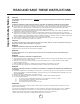
Important safety Notice READ AND SAVE THESE INSTRUCTIONS CAUTION: FOR GENERAL VENTILATING USE ONLY. DO NOT USE TO EXHAUST HAZARDOUS OR EXPLOSIVE MATERIALS OR VAPORS. WARNING TO REDUCE THE RISK OF FIRE, ELECTRIC SHOCK, OR INJURY TO PERSONS, OBSERVE THE FOLLOWING: A. Use this unit only in the manner intended by the manufacturer. If you have questions, contact the manufacturer. B.
ELECTRICAL REQUIREMENTS Important: Observe all governing codes and ordinances. It is the customers responsibility: To contact a qualified electrical installer. To assure that the electrical installation is adequate and in conformance with National Electrical Code, ANSI/NFPA 70 latest edition*, or CSA Standards C22.1-94, Canadian Electrical Code, Part 1 and C22.2 No.0-M91 - latest edition** and all local codes and ordinances.
List of Materials PARTS SUPPLIED: Blower unit housing Hood canopy Metal filter x 1 Halogen light bulb x 4 Upper and lower Duct covers x 4 Chimney structure Hardware Packet: Allen spanner x 1 Template Use, Care and Installation guide Nuts x 12 7x45 screws x 6 4 x 6 screws x 12 (to assemble duct covers) 3,5x6,5 screws x 13 (11 to assemble Hood canopy to Chimney structure + 2 to fix duct covers to chimney structure).
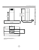
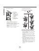
*min. 31" 10/16 *max. 49" min. 30" 8/16 max. 43" 14/16 26" 4/16 1" 27" 8/16 42" - 48" 12" 3/16 14" * Ductless (recirculating) version ONLY Note: if necessary order the proper duct cover extension kit. 7 Dimensions and clearances www.zephyronline.
Installation Instructions Closely follow the instructions set out in this manual. All responsibility, for any eventual inconveniences, damages or fires caused by not complying with the instructions in this manual, is declined. VENTING METHODS The hood is equipped with a transition B for discharge of fumes to the outside (Ducting version). Should it not be possible to discharge cooking fumes and vapour to the outside, the hood can be used in the Ductless (recirculating) version.
Duct pieces Equivalent number lenght x used = Duct pieces Total Equivalent number lenght x used = Total 3 1/4 x 10 Rect., straight 1 Ft. x( )= Ft. 6" Round wall cap with damper 30 Ft. x ( )= Ft. 6 Round,, straight 1 Ft. x( )= Ft. 6 Round, roof cap 30 Ft. x ( )= Ft. 7", 8 Round,, straight 1 Ft. x( )= Ft. 6 Round to 3 1/4 x 10 rect. transition 1 Ft. x( )= Ft. 3 1/4 x 10 Rect.90° elbow 15 Ft. x ( )= Ft. 16 Ft. x ( )= Ft. 3 1/4 x 10 Rect.45° elbow 9 Ft.
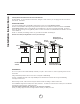
Installation 2. Preparation of mounting surface 1. Pre-installation calculations Installing supports above ceiling drywall. Ceiling S H K P 1" 3/8 C (36" std) Template K = Kitchen Height C = Counter Height (36" standard) P = Prefered Height of Hood Bottom above counter (recommended 24-32) H = Hood height your installation H= KCP S = Chimney Structure Height, your installation. S = H 1 3/8 a) Select a hood preference height P that is comfortable for the user. (from 24 to 32).
c. Install a 8 exhaust duct and extend length = S - 16 5/8 from ceiling. Duct shall be securely fastened to joists. Do not use duct smaller than specified. Attention: Duct installation is not required for nonvented (recirculating) installations d. Install 1/2" electrical conduit in location marked on template and extend length = S - 11 1/8 from ceiling. Note: If a Remote ventilator installation is required/ needed, then provide an additional hole/conduit. e.
Installation 8. Electrical connection Conduit WARNING Electrical Shock Hazard Warning: Turn off power circuit at the service panel before wiring this unit. 120 VAC, 15 or 20 Amp circuit required. J-Box cover ELECTRICAL GROUNDING INSTRUCTIONS THIS APPLIANCE IS FITTED WITH AN ELECTRICAL JUNCTION BOX WITH 3 WIRES, ONE OF WHICH (GREEN/YELLOW) SERVES TO GROUND THE APPLIANCE.
d. Fasten the canopy with 11 screws from the bottom. 12. Fix 6 nuts on the internal side of top duct covers sections (squere slots) and fix each other with 6 screws (3 per side). Rectangular slots Nut FRONT Plan diagram FRONT top sections top sections Chimney Structure 13. Install top duct covers assembly to the chimney structure. Fix with 2 screws. Note: Upper Duct Cover may be placed upside down to hide (or unhide) ventless slots. FRONT Bottom View 13 Installation www.zephyronline.
Installation 14. Fix 6 nuts on the internal side of rear bottom duct covers section (square slots - see drawings after step 11) and place it on the rear side of the hood on top the canopy, cheack that it snaps with top duct covers assembly. 15. Fit the front bottom duct covers section and fix both sections with 8 screws each other (the lower screws fix duct cover to canopy).
www.zephyronline.com Installation 17. Assemble the lower (narrow) trim strips to the lower vent cover assembly. Cut the upper (wide) trim strips to length to fit the upper duct cover assembly. Assemble the upper trim strips to the upper duct cover assembly. Upper tab Upper tab X X Lower tab Lower tab 18. Check all light bulbs to make sure they are secure in their sockets. Turn power on in service panel. Check lights and blower operation per Care & Use section of this manual.
Description of the hood & Controls 1 2 3 4 5 6 7 Control panel Grease filter Grease filter release handle Halogen lamp (position and nr. of lamps may vary) Hood canopy Duct cover Air outlet (used for Ductless version only) 7 6 1 3 2 4 5 CONTROLS Use the high suction speed in cases of concentrated kitchen vapours.
Prior to any maintenance operation ensure that the cooker hood is disconnected from the power supply. CLEANING The cooker hood should be cleaned regularly internally and externally. For cleaning use a cloth moistened with a neutral liquid detergents. Avoid abrasive detergents. Warning: Failure to carry out the basic standards of the cleaning of the cooker hood and replacement of the filters may cause fire risks. Therefore we recommend oserving these instructions.
Trouble Shooting Issue After installation, the unit doesnt work? Cause What to do 1. The power source is not turned ON. 1. Make sure the circuit breaker and the units power is ON. 2. The power line and the cable locking connector is not connecting properly. 2. Check the power connection with the unit is connected properly. 3. The switch board and control board wirings are disconnected. 3. Make sure the wirings between the switch board and control board are connected properly. 4.
TO OBTAIN SERVICE UNDER WARRANTY: Staple your receipt here. Proof of the original purchase date is needed to obtain service under the warranty. or any Service Related Questions, please call: 1-888-880-8368 TO OBTAIN SERVICE UNDER WARRANTY: You must present proof of original purchase date. Please keep a copy of your dated proof of purchase (sales slip) in order to obtain service under warranty.
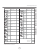
List of Parts and Accessories Part Description halogen bulb, 12V 20 W Part# Z0B-0013 metal filter Part Description Part# Ductless recirculating kit ZRC-00AL charcoal replacement filter Z0F-C060 duct cover extension kit Z1C-00AL internal blower - 600 cfm EBI-600A in-line blower - 1100 cfm EBN-1100A 20
www.zephyronline.