www.zephyronline.
E page 2 F page 25 S page 50 APPROVED FOR RESIDENTIAL APPLIANCES FOR RESIDENTIAL USE ONLY READ AND SAVE THESE INSTRUCTIONS PLEASE READ ENTIRE INSTRUCTIONS BEFORE PROCEEDING. INSTALLATION MUST COMPLY WITH ALL LOCAL CODES. IMPORTANT: Save these Instructions for the Local Electrical Inspector’s use. INSTALLER: Please leave these Instructions with this unit for the owner. OWNER: Please retain these instructions for future reference.
Important safety Notice ..................................................................... 4 Electrical & Installation requirements ............................................. 5 Electrical requirements .............................................................. 5 Before installing the hood ........................................................... 5 List of Materials ................................................................................. 6 Parts supplied: .................................
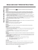
Important safety Notice READ AND SAVE THESE INSTRUCTIONS CAUTION: FOR GENERAL VENTILATING USE ONLY. DO NOT USE TO EXHAUST HAZARDOUS OR EXPLOSIVE MATERIALS OR VAPORS. WARNING TO REDUCE THE RISK OF FIRE, ELECTRIC SHOCK, OR INJURY TO PERSONS, OBSERVE THE FOLLOWING: A. Use this unit only in the manner intended by the manufacturer. If you have questions, contact the manufacturer. B.
ELECTRICAL REQUIREMENTS Important: Observe all governing codes and ordinances. It is the customer’s responsibility: • To contact a qualified electrical installer. • To assure that the electrical installation is adequate and in conformance with National Electrical Code, ANSI/NFPA 70 — latest edition*, or CSA Standards C22.1-94, Canadian Electrical Code, Part 1 and C22.2 No.0-M91 - latest edition** and all local codes and ordinances.
List of Materials PARTS SUPPLIED: • • • • • • Blower unit housing Top cover Hood canopy Metal grease filter x 1 Halogen light bulb x 2 Hardware Packet: Remote Control Transition for Rear/Horizontal discharge + backdraft damper Allen spanner x 1 Hook x 2 Rubber tape (section in mm: 20x5) for back of range hood Rubber tape (section in mm: 8x8) for hear/horizontal discharge Transition Use, Care and Installation guide Template Screw 3,5x9,5 x 2 (to fix the transition on top of the hood - Vertical discharge) S
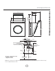
17" 1/2 22" 1/16 31" 1/2 min 47" 14/16*** max 65" 3/16*** min 38" 13/16** max 47" 8/16** 29" 7/16 33" 15/16 7" 1/16 13" 3/4 2" 3/8 ceiling 1" 1/4 Conduit (vertical-horizontal discharge) and Ducting area passage (Vertical discharge only - Duct bends are not considered) rear wall 13" 3/4 Ducting area passage horizontal discharge 3" 3/4 10" 7/16 24" 5/16 32" 28" 5/8* Side Cabinet Side Cabinet 32" min.
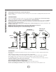
Installation Instructions Closely follow the instructions set out in this manual. All responsibility, for any eventual inconveniences, damages or fires caused by not complying with the instructions in this manual, is declined. VENTING METHODS The hood is equipped to discharge of fumes to the outside towards the rear (Ducting version - Horizontal discharge). Fumes may be discharged towards the top side (Ducting version - Vertical discharge).
Duct pieces Equivalent number lenght x used = Duct pieces Equivalent number lenght x used = Total Total 3 1/4 ” x 10” Rect., straight 1 Ft. x( )= Ft. 6" Round 30 Ft. wall cap with damper x( )= Ft. 6 ” Round,, straight 1 Ft. x( )= Ft. 6” Round, roof cap 30 Ft. x( )= Ft. 7", 8” Round,, straight 1 Ft. x( )= Ft. 6” Round to 3 1/4 ” x 10” rect. transition 1 Ft. x( )= Ft. 3 1/4 ” x 10” Rect.90° elbow 15 Ft. x( )= Ft. 16 Ft. x( )= Ft. 3 1/4 ” x 10” Rect.45° elbow 9 Ft.
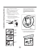
Installation- Discharge direction This hood is shipped ready for Horizontal discharge. To change to Vertical discharge proceed as follows: Note1: when proceeding keep all screws and memorize the way all components are fixed. Note2 - For Vertical discharge ONLY: The installation of the Low or High Duct Cover kit is recommended. a. open the front door and remove the metal filter (see paragraph "Maintenance - Front Door" and "Maintenance - Grease filter"). c.
Installation- Discharge direction www.zephyronline.com e. Remove the blower from the metal filter housing. f. Reposition the blower/bracket assembly so that discharge outlet is towards the top side (Vertical discharge), firmly tighten the 4 fixing screws. WARNING! When performing this step check that wirings run in a proper way, DO NOT DAMAGE OR PULL WIRINGS! Vertical discharge Horizontal discharge g.
Installation 8. Note: all fastener locations must span the studs otherwise proceed as follows: Cutout drywall along marked lines. Install each necessary between studs firmly flush with already existing stud front. Make sure all mounting screws will anchor to added studs. Replace drywall and refinish. Installation 1. If possible, disconnect and move freestanding or slide-in range from cabinet opening to provide easier access to rear wall.
10. Ducting Version-horizontal discharge ONLY: Connect ducting to transition for horizontal discharge, seal with duct tape and fix transition to the wall with four screws, use the included adhesive rubber tape to seal with hood once mounted. 11. Determine position of the conduit and cut a 1-1/4" (3.2 cm) hole at this location. Position the conduit. Run wires through hole according the National Electrical Code or CSA Standards and local codes and ordinances.
Installation 15. Hang hood on hooks with the 2 brackets. 18. Ducting version - vertical discharge ONLY: Install the transition on top of the hood with 2 screws. Connect ducting to transition. Seal with duct tape. Do not use duct smaller than the transition. Ductless (recirculating) version ONLY: Install the deflector (available as an extra kit). on top of the hood. WARNING Excessive Weight Hazard - Use two or more people to move and install range hood. Failure to do so can result in back or other injury.
Connect black wire from service panel to black or red in junction box, white to white and green to green-yellow. Controls start flashing for about 15 secs to indicate they are calibrating themselves, wait until flashing stops (only Motor touch sensor key OFF (stand by) is ON - see also paragraph "Controls"). Calibration is repeated any time the hoos is disconnected intentionally or not from power supply (i.e.: Black out). Then check lights and blower operation. Close junction box cover. 20.
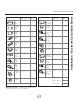
Description of the hood 1 2 3 4 5 6 Control panel Grease filter Grease filter release handle Halogen lamp (position and nr.
Use the high suction speed in cases of concentrated kitchen vapours. It is recommended that the cooker hood suction is switched on for 5 minutes prior to cooking and to leave in operation during cooking and for another 15 minutes approximately after terminating cooking.
Description of the hood - Remote Control Using the Remote Control This device complies with part 15 of the FCC Rules. Operation is subject to the following two conditions: (1) This device may not cause harmful interference, and (2) this device must accept any interference received, including interference that may cause undesired operation. The remote control may operate in humid environments, but not when placed on wet surfaces.
Prior to any maintenance operation ensure that the cooker hood is disconnected from the power supply. GREASE FILTER This must be cleaned once a month using non aggressive detergents, either by hand or in the dish-washer, which must be set to a low temperature and a short cycle. When washed in a dish-washer, the grease filter may discolour slightly, but this does not affect its filtering capacity. To remove the grease filter, pull the spring release handle (a-b).
Trouble Shooting Issue After installation, the unit doesn’t work? Light works, but motor is not turning. The unit is vibrating. The motor is working, but the lights are not. The hood is not venting out properly. Metal filter is vibrating. Cause What to do 1. The power source is not turned ON. 1. Make sure the circuit breaker and the unit’s power is ON. 2. The power line and the cable locking connector is not connecting properly. 2. Check the power connection with the unit is connected properly.
TO OBTAIN SERVICE UNDER WARRANTY: Staple your receipt here. Proof of the original purchase date is needed to obtain service under the warranty. or any Service Related Questions, please call: 1-888-880-8368 TO OBTAIN SERVICE UNDER WARRANTY: You must present proof of original purchase date. Please keep a copy of your dated proof of purchase (sales slip) in order to obtain service under warranty.
List of Parts and Accessories Part Description Part# halogen bulb, 12V 20 W Z0B-0009 metal filter GF009C remote control battery ..394 of 1.5V.
www.zephyronline.