
Owners Guide


29
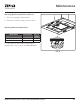
Modena Island Use, Care, and Installation Guide
ZEPHYRONLINE.COM
FIG. L
PC Board
1
3
5
7
2
4
6
8
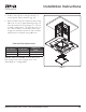
Jumper 5-6 or 7-8
DEFAULT POSITION
Default Max. Blower CFM
Jumper 3-4
Max. Blower CFM
390
Jumper 1-2
Jumper Pins
Plastic
Jumper
1
3
5
7
2
4
6
8
1
3
5
7
2
4
6
8
1
3
5
7
2
4
6
8
Max. Blower CFM
290
FIG. M
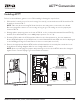
ACT™ Conversion
Enabling ACT™
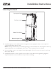
Before hood installation, gain access to PC board by following the steps below:
1. PC board is located on top of motor housing. Unscrew (4) screws and remove PC board from PC
board box shown in FIG. L.
NOTE: Take care when removing PC board as there are many wires connected to the board.
Disconnecting all the wires is not necessary as long as you can easily access the jumper pins
shown in FIG. M.
2. Change plastic jumper position as shown in FIG. M. to the set desired maximum blower CFM. By
default, the maximum CFM is set to 600 (jumper position 5-6 or 7-8).
3. Re-attach PC board to the PC board box. When hood is first powered on, the new maximum
blower CFM will appear on the LCD for two seconds. Maximum blower CFM can also be displayed
on the LCD by pressing the Power Button for three seconds (with hood o.)
4. Remove the appropriate blower CFM sticker included with this sheet and place inside the hood
body below the wiring diagram label or in a clearly visible location.
NOTE: After re-positioning the jumper and powering on the hood, the CFM cannot be changed
again. Please contact Zephyr if you need further assistance.