WWW.ZEPHYRONLINE.COM Anzio Island ZAZ-M90DS ZAZ-E42DS Luce Island ZLC-M90CS ZLC-E42CS Roma Island ZRM-E36FS ZRM-E42FS Ravenna Island ZRE-M90BBSGG ZRE-E42BBSGG EN Use, Care, and Installation Guide FR Guide d’utilisation, d’entretien et d’installation C TM Airflow Control Technology MAR22.
CORE Z A Z , Z LC, Z R M , Z R E ISLAND 2 Anzio Island, Luce Island, Roma Island, Ravenna Island Use, Care, and Installation Guide
Contents ZEPHYRONLINE.COM Page Safety Information............................................................................. 4-6 Types of Safety Warnings.................................................................... 4 General Safety...................................................................................4-5 Operation............................................................................................ 6 Electrical Requirements.........................................................
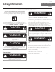
CORE Safety Information Z A Z , Z LC, Z R M , Z R E ISLAND READ AND SAVE THESE INSTRUCTIONS Your safety and the safety of others are very important. We have provided many important safety messages in this manual for your appliance. Always read and obey all safety messages. WARNING WARNING - TO REDUCE THE RISK OF FIRE, ELECTRIC SHOCK, OR INJURY TO PERSONS, OBSERVE THE FOLLOWING: a) Use this unit only in the manner intended by the manufacturer. If you have questions, contact the manufacturer.
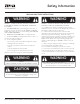
Safety Information ZEPHYRONLINE.COM READ AND SAVE THESE INSTRUCTIONS WARNING WARNING - TO REDUCE THE RISK OF INJURY TO PERSONS IN THE EVENT OF A RANGE TOP GREASE FIRE, OBSERVE THE FOLLOWINGa: a) SMOTHER FLAMES with a close-fitting lid, cookie sheet, or metal tray, then turn off the burner. BE CAREFUL TO PREVENT BURNS. If the flames do not go out immediately, EVACUATE AND CALL THE FIRE DEPARTMENT. b) NEVER PICK UP A FLAMING PAN – You may be burned.
CORE Safety Information Z A Z , Z LC, Z R M , Z R E ISLAND READ AND SAVE THESE INSTRUCTIONS Operation ► Always leave safety grilles and filters in place. Without these components, operating blowers could catch onto hair, fingers and loose clothing. ► The manufacturer declines all responsibility in the event of failure to observe the instructions given here for installation, maintenance and suitable use of the product.
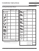
List of Materials ZEPHYRONLINE.
CORE Installation Instructions Z A Z , Z LC, Z R M , Z R E ISLAND Ducting Calculation Sheet Equivalent number length x used = Duct pieces 1 Ft. x( ) = Ft. 6”, 7”, 8”, 10” 1 Ft. Round, straight x( ) = Ft. 3-1/ 4” x 10” Rect. 900 elbow 15 Ft. x( ) = Ft. 3-1/ 4” x 10” Rect. 450 elbow 9 Ft. x( ) = 3-1/ 4” x 10” Rect., straight 3-1/ 4” x 10” Rect. 900 flat elbow 24 Ft. x( 7” to 6” or 25 Ft. 8” to 7” Round tapered reducer x( 15 Ft.
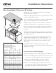
Installation Instructions ZEPHYRONLINE.COM Mounting Height, Clearance, & Ducting A minimum of 6” round duct must be used to maintain maximum air flow efficiency. Always use rigid type metal ducts only. Flexible ducts could restrict air flow by up to 50%. A n. mi . B n mi x. C a m D n. mi . E n mi x. F a m Also use calculation (on page 8) to compute total available duct run when using elbows, transitions and caps. ALWAYS, when possible, reduce the number or transitions and turns.
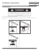
CORE Installation Instructions Z A Z , Z LC, Z R M , Z R E ISLAND Ducting Options WARNING Fire Hazard: NEVER exhaust air or terminate ductwork into spaces between walls, crawl spaces, ceilings, attics, or garages. All exhaust must be ducted to the outside, unless using the recirculating option. ► Use single wall rigid metal ductwork only. ► Fasten all connections with sheet metal screws and tape all joints w/ certified Silver Tape or Duct Tape.
Installation Instructions ZEPHYRONLINE.COM ZAZ Hood Specifications 11” 10-5/8” 5-1/4” 35-7/16”, 41-15/16” 25-9/16” FRONT SIDE 7-9/16” 3-9/16” C/L 5-15/ 16” 3-1/2” C/L 8-1/8” 8-1/4” C/L AC In 1-7/8” TOP 13/16” 1-1/4” Z1C-00AZ min. ducted - 47” min. recirc. - 51” max. - 80” 1-3/16” 16-9/16” 5-5/16” 9-7/16” STANDARD min. ducted - 31-1/2” min. recirc. - 36” max.
CORE Installation Instructions Z A Z , Z LC, Z R M , Z R E ISLAND ZLC Hood Specifications 11” 10-5/8” Z1C-00LC min. ducted - 47” min. recirc. - 51” max. - 80” 2-1/16” 12-3/8” 9-7/16” STANDARD min. ducted - 29” min. recirc. - 32-1/2” max.
Installation Instructions ZEPHYRONLINE.COM ZRM Hood Specifications 12” 14” 9-11/16” STANDARD min. ducted - 28” min. recirc. - 31” max. - 39” 3” 11-3/16” Z1C-01RM EXTENSION min. ducted - 50-1/2” min. recirc. - 50-1/2” max.
CORE Installation Instructions Z A Z , Z LC, Z R M , Z R E ISLAND ZRE Hood Specifications 10-7/8” Z1C-01REBS EXTENSION min. ducted - 48-1/2” min. recirc. - 48-1/2” max. - 78” 13-3/4” 5/16 ” 23-15/16” 3-9/16” STANDARD min. ducted - 28-1/2” min. recirc. - 28-1/2” max. - 38” 24-1/2” (top of electrical box) 10-3/8” 35-3/16” 25-9/16” FRONT SIDE 8” 8-3/4” 6” 11-5/8” 3-3/4” C/L TOP 14 4-3/16” 5/8” 2-3/4” 4-3/8” elec.
Installation Instructions ZEPHYRONLINE.COM Electrical Supply WARNING Electrical wiring must be done by qualified person(s) in accordance with all applicable codes and standards. Turn off electrical power at service entrance before wiring. For personal safety, remove house fuse or open circuit breaker before beginning installation. Do not use extension cord or adapter plug with this appliance. Follow national electrical codes or prevailing local codes and ordinances.
CORE Installation Instructions Z A Z , Z LC, Z R M , Z R E ISLAND Mounting the Hood CAUTION Ceiling Joists 1 Wood Blocking At least two installers are required due to the weight and size of the hood. 2 Top Support Frame 1. Determine mounting location on ceiling and temporarily tape paper template (included with the hood) to the ceiling. Cut out internal shaded area of template to allow the ducting and electrical to pass through. If necessary, add wood blocking (min.
Installation Instructions ZEPHYRONLINE.COM Mounting the Hood 3. Lift support frame assembly up to the ceiling making sure the word “front” on the top support frame faces the front of the hood where the controls will be located. (FIG. D) The key holes on the top support frame should cover the wood screws previously installed in the ceiling. Slide support frame towards narrow end of key holes to lock the frame in place.
CORE Installation Instructions Z A Z , Z LC, Z R M , Z R E ISLAND Mounting the Hood 8. Assemble Top Duct Covers (with louver holes) together over Top Support Frame, secure Top Duct Covers together by magnetic strips. NOTE: If using hood in ductless recirculating mode, you must install the air diverter plate to the Top Support Frame prior to assembling the duct covers. 1 Top Support Frame Top Duct Covers 9.
Installation Instructions ZEPHYRONLINE.COM Ductless Recirculation Ductless recirculation is intended for applications where an exhaust duct work is not possible to be installed. When converted, the hood functions as a recirculating hood rather than an exhaust hood. Fumes and exhaust from cooking are drawn and filtered by a set of optional charcoal filters. The air is then purified and re-circulated back within the home.
CORE Features & Controls Z A Z , Z LC, Z R M , Z R E ISLAND ICON Touch Controls Power / Delay Off Adjust 5 Speed Levels Lights Low/High/Off 5 Lighted Glass Button Display (speed level, delay off, filter clean/change) 1 POWER / DELAY OFF BUTTON Power Button Function MODEL ZLC ONLY - Button will turn power on and off for entire hood (fan and lights). - Hood will remember the last speed and light level it was turned off at. (Example: Press Button to turn off hood when on fan speed 4 and high lights.
Features & Controls ZEPHYRONLINE.COM ICON Touch Controls 3 LIGHTS BUTTON - Lights have two levels, Low and High. - From off, press one time for Low. Press again for High. Press again to power lights off. 4 DISPLAY INDICATORS Mesh Filter Clean Reminder (always enabled) - After 30 hours of fan usage, the button indicator will begin to slowly blink indicating it is time to clean the mesh filters. - To reset: With hood off: hold the button for three seconds.
CORE Features & Controls Z A Z , Z LC, Z R M , Z R E ISLAND Optional RF Remote Control To enable RF remote control capabilities, the remote control accessory kit is required. The part number for the kit is RC-0002. FCC Caution To assure continued compliance, any changes or modifications not expressly approved by the party responsible for compliance could void the user’s authority to operate this equipment. (Example use only shielded interface cables when connecting to computer or peripheral device.
Features & Controls ZEPHYRONLINE.COM Optional RF Remote Control RF Remote Features The RF remote control is equipped with a magnet on the back for easy storage. The remote may be placed on any magnetic surface such as a refrigerator or the Zephyr remote holder, FIG. I. The remote holder can be inserted into a standard electrical outlet for easy storage. Note: The remote holder does not charge the RF remote. Maximum remote control communication distance is 15 feet from the liner. FIG.
CORE Maintenance Z A Z , Z LC, Z R M , Z R E ISLAND Hood & Filter Cleaning Surface Maintenance ► Do not use corrosive detergents, abrasive detergents or oven cleaners. ► Do not use any product containing chlorine bleach or any product containing chloride. ► Do not use steel wool or abrasive scrubbing pads which will scratch and damage surface. Cleaning Stainless Steel Clean periodically with warm soapy water and clean cotton cloth or micro fiber cloth.
Maintenance ZEPHYRONLINE.COM Installing the Grease Filters (FIG. K): 1. Pull down on filter latch to release the filter tabs. 2. Pull down on front of filter to remove the grease filters. FIG. K LumiLight LED In the unlikely event that your LumiLight LED fails, please contact Zephyr to order replacement parts. See the list of parts and accessories page for part numbers and contact information. LED Removal (FIG. L): 1. Remove grease filters. 2.
CORE ACT™ Conversion Z A Z , Z LC, Z R M , Z R E ISLAND Airflow Control Technology (ACT™) Some local codes limit the maximum amount of CFM a range hood can move. ACT™ allows you to control the maximum blower CFM of select Zephyr Ventilation range hoods without the need for expensive make up air kits. ACT™ enables the installer to easily set the maximum blower speed to one of two most commonly specified CFM levels; 390 or 290 CFM. The usage of ACT™ may not be necessary for your installation.
ACT™ Conversion ZEPHYRONLINE.COM Enabling ACT™ To enable ACT™: 1. Before hood installation, gain access to PC board by following the steps shown on FIG. M. 2. Change plastic jumper positioning as shown in FIG. N to set the desired maximum blower CFM. 3. Re-install PC board and continue with hood installation. 4. Remove the appropriate foil CFM sticker included with the hood literature and place inside the hood body below the wiring diagram or in another clearly visible location.
CORE Wiring Diagram Z A Z , Z LC, Z R M , Z R E ISLAND ZAZ-E42DS, ZAZ-M90DS Wiring Diagram Volts Hz 120 60 Max. Amps 4 Red Blue Brown Motor Red Yellow Grey White Green Body Yellow Yellow Black White White Black Green Body Yellow REMARKS: CONDENSER 12.5+12.
Wiring Diagram ZEPHYRONLINE.COM ZLC-M90CS, ZLC-E42CS Wiring Diagram Volts Hz 120 60 Max. Amps 4 Green Body Brown Grey Yellow Blue Yellow Motor Control PC Red Red Yellow White Black White REMARKS: CAPACITOR 12.5+12.
CORE Wiring Diagram Z A Z , Z LC, Z R M , Z R E ISLAND ZRM-E36FS, ZRM-E42FS Wiring Diagram Volts Hz 120 60 Max. Amps 4 Green Body Motor Red Red Yellow Blue Brown Grey White Yellow Yellow Yellow Yellow Control White Black Green Body REMARKS: CONDENSER 12.5+12.
Wiring Diagram ZEPHYRONLINE.COM ZRE-M90BBSGG ZRE-E42BBSG Wiring Diagram Volts Hz Max. Amps 120 60 4 Body Green Red Motor White Yellow Yellow White Black Red Yellow Blue Brown Grey Yellow Yellow Control White Black Green Body REMARKS: CONDENSER 12.5+12.
CORE Troubleshooting Z A Z , Z LC, Z R M , Z R E ISLAND Possible Problem After installation, the unit doesn’t work. Light works, but blower is not turning. The unit is vibrating. Possible Cause The power source is not turned ON. The power line and the cable locking connector is not connecting properly. The switch board or control board is defective. The switch board or control board wirings are disconnected. The blower is defective, possibly seized.
Troubleshooting ZEPHYRONLINE.COM Possible Problem The hood is not venting out properly. Filter is vibrating. RF Remote control does not work. Possible Cause Solutions Using the wrong size of ducting. Change the ducting to the correct size The hood might be hanging to high from the cook top. Adjust the distance between the cooktop and the bottom of the hood within 24” to 34” range. Close all the windows and doors to eliminate the outside wind flow.
CORE List of Parts & Accessories Z A Z , Z LC, Z R M , Z R E ISLAND Description ZAZ Replacement Parts LumiLight LED, 6W Aluminum Mesh Filter (each) Charcoal Filter (each) ZAZ Optional Accessories Extension Duct Cover Recirculating Kit Hybrid Baffle Filter Kit (2 filters) ZLC Replacement Parts LumiLight LED, 6W Aluminum Mesh Filter (each) Charcoal Filter (each) ZLC Optional Accessories Extension Duct Cover Recirculating Kit ZRM Replacement Parts LumiLight LED, 6W Aluminum Mesh Filter (each) Charcoal Filte
Limited Warranty ZEPHYRONLINE.COM Limited Warranty TO OBTAIN SERVICE UNDER WARRANTY OR FOR ANY SERVICE RELATED QUESTIONS United States Customers please call: 1-888-880-8368 or contact us at: zephyronline.com/contact Canada Customers please call: 1-800-361-0799 or Email: service@distinctive-online.
CORE Product Registration Z A Z , Z LC, Z R M , Z R E ISLAND Congratulations on the purchase of your Zephyr product! Please take a moment to register your new Zephyr product at www.zephyronline.com/registration IT’S IMPORTANT Prompt registration helps in more ways than one. Ensures warranty coverage should you need service. Ownership verification for insurance purposes. Notification of product changes or recalls. Zephyr Ventilation | 2277 Harbor Bay Pkwy. | Alameda, CA 94502 | 1.888.880.
WWW.ZEPHYRONLINE.COM Anzio Island ZAZ-M90DS ZAZ-E42DS Luce Island ZLC-M90CS ZLC-E42CS Roma Island ZRM-E36FS ZRM-E42FS Ravenna Island ZRE-M90BBSGG ZRE-E42BBSGG EN Use, Care, and Installation Guide FR Guide d’utilisation, d’entretien et d’installation C TM Airflow Control Technology MAR22.
CORE Z A Z , Z LC, Z R M , Z R E ÎLE 2 ZAZ, ZLC, ZRM, ZRE Guide d’utilisation, d’entretien et d’installation
Table des matières ZEPHYRONLINE.COM Page Consignes de sécurité........................................................................ 4-6 Types d’avertissements de sécurité...................................................... 4 Sécurité générale................................................................................4-5 Opération............................................................................................ 6 Exigences électriques.......................................................
CORE Consignes de sécurité Z A Z , Z LC, Z R M , Z R E ÎLE LISEZ ET CONSERVEZ CES INSTRUCTIONS Votre sécurité et celle des gens qui vous entourent sont très importantes. Ce manuel contient de nombreux messages de sécurité relatifs à votre appareil. Lisez tous les messages et conformez-vous-y en tout temps.
Consignes de sécurité ZEPHYRONLINE.
CORE Consignes de sécurité Z A Z , Z LC, Z R M , Z R E ÎLE LISEZ ET CONSERVEZ CES INSTRUCTIONS Opération ► Laissez toujours les grilles de sécurité et les filtres en place. Sans ces composants, les soufflantes en fonctionnement pourraient s’accrocher aux cheveux, aux doigts et aux vêtements amples. ► Le fabricant décline toute responsabilité en cas de non-respect des instructions données ici pour l’installation, la maintenance et l’utilisation appropriée du produit.
Liste de matériel ZEPHYRONLINE.
CORE Instructions d’installation Z A Z , Z LC, Z R M , Z R E ÎLE Feuille de calcul pour le conduit d’aération Longueur x Nombre utilisé Pièces de conduit = 1 pi x( ) = pi 6”, 7”, 8”, 10” 1 pi circ., droit x( ) = pi 3-1/ 4” x 10” rect., coude à 90º 15 pi x( ) = pi 3-1/ 4” x 10” rect., coude à 45º 9 pi x( ) = pi 6” circ. à rect. de 3-1/4" x 10" pi 16 pi 6” circ. à rect. de 3-1/4" x 10", coude à 90º pi 7” circ. à rect. de 3-1/4" x 10" 3-1/ 4” x 10” rect., droit 3-1/ 4” x 10” rect.
Instructions d’installation ZEPHYRONLINE.COM Hauteur de montage, dégagement et gaine A n. mi . B n mi x. C a m D n. mi . E n mi x. F a m n. mi x.
CORE Instructions d’installation Z A Z , Z LC, Z R M , Z R E ÎLE Options de conduits ATTENTION Risque d’incendie: NE JAMAIS évacuer l’air ni terminer de conduits dans des espaces entre les murs, les vides sanitaires, les plafonds, les greniers ou les garages. Tout l’échappement doit être canalisé vers l’extérieur, à moins d’utiliser l’option de recirculation. ► Utilisez uniquement des conduits métalliques rigides à paroi simple.
Instructions d’installation ZEPHYRONLINE.COM ZAZ Spécifications de la hotte 11 po 10-5/8 po 5-1/4 po 35-7/16 po, 41-15/16 po 25-9/16 po DE FACE CÔTÉ 7-9/16 po 3-9/16 po po 3-1/2 po C/L 8-1/4 po C/L 13/16 po 16 8-1/8 po 1-1/4 po C/L 5-15/ Z1C-00AZ min. ducted - 47 po min. recirc. - 51 po max. - 80 po 1-3/16 po 16-9/16 po 5-5/16 po 9-7/16 po LA NORME min. ducted - 31-1/2 po min. recirc. - 36 po max.
CORE Instructions d’installation Z A Z , Z LC, Z R M , Z R E ÎLE ZLC Spécifications de la hotte 11 po 10-5/8 po 9-7/16 po LA NORME min. canalisé - 29 po min. recirc. - 32-1/2 po max. - 46-1/2 po 12-3/8 po 2-1/16 po Z1C-00LC min. canalisé - 47 po min. recirc. - 51 po max.
Instructions d’installation ZEPHYRONLINE.COM ZRM Spécifications de la hotte 12 po 14 po 9-11/16 po LA NORME min. canalisé - 28 po min. recirc. - 31 po max. - 39 po 3 po 11-3/16 po Z1C-01RM EXTENSION min. canalisé - 50-1/2 po min. recirc. - 50-1/2 po max.
CORE Instructions d’installation Z A Z , Z LC, Z R M , Z R E ÎLE ZRE Spécifications de la hotte 10-7/8 po Z1C-01REBS EXTENSION min. ducted - 48-1/2 po min. recirc. - 48-1/2 po max. - 78 po po 23-15/16 po 3-9/16 po LA NORME min. ducted - 28-1/2 po min. recirc. - 28-1/2 po max. - 38 po 24-1/2 po (haut du coffret électrique) 10-3/8 po 5/16 13-3/4 po 35-3/16 po 25-9/16 po DE FACE CÔTÉ 6 11-5/8 po 8 po 3-3/4 po 8-3/4 po po C/L HAUT 4-3/16 po 5/8 po 2-3/4 po 4-3/8 po elec.
Instructions d’installation ZEPHYRONLINE.COM Fourniture électrique ATTENTION Le câblage électrique doit être effectué par des personnes qualifiées conformément à tous les codes et normes applicables. Cette hotte doit être correctement mise à la terre. Coupez l’alimentation électrique à l’entrée de service avant le câblage. Pour votre sécurité personnelle, retirez le fusible de la maison ou ouvrez le disjoncteur avant de commencer l’installation.
CORE Instructions d’installation Z A Z , Z LC, Z R M , Z R E ÎLE Montage de la hotte AVERTISSEMENT Solives de plafond 1 Blocage en bois Au moins deux installateurs sont nécessaires en raison du poids et de la taille de la hotte. 2 Cadre de support supérieur 1. Déterminez l’emplacement de montage au plafond et collez temporairement le gabarit en papier (inclus avec la hotte) au plafond. Découpez la zone ombrée interne du gabarit pour permettre le passage des conduits et de l’électricité.
Instructions d’installation ZEPHYRONLINE.COM Montage de la hotte 3. Soulevez l’assemblage du cadre de support jusqu’au plafond en vous assurant que le mot « avant » sur le cadre de support supérieur fait face à l’avant de la hotte où les commandes seront situées. (FIG. D) Les trous de serrure sur le cadre de support supérieur doivent couvrir les vis à bois précédemment installées dans le plafond.
CORE Instructions d’installation Z A Z , Z LC, Z R M , Z R E ÎLE Montage de la hotte 8. Assemblez les couvercles supérieurs du conduit (avec des trous d’aération) sur le cadre de support supérieur, fixez les couvercles supérieurs du conduit ensemble à l’aide de bandes magnétiques. REMARQUE: Si vous utilisez une hotte en mode de recirculation sans conduit, vous devez installer la plaque de dérivation d’air sur le cadre de support supérieur avant d’assembler les couvercles de conduit. 9.
Instructions d’installation ZEPHYRONLINE.COM Recirculation sans conduit La recirculation sans conduit est destinée aux applications où un conduit d’évacuation ne peut pas être installé. Une fois convertie, la hotte fonctionne comme une hotte à recirculation plutôt que comme une hotte aspirante. Les fumées et les gaz d’échappement de la cuisson sont aspirés et filtrés par un ensemble de filtres à charbon en option. L’air est ensuite purifié et recyclé dans la maison.
CORE Fonctionnalités et commandes Z A Z , Z LC, Z R M , Z R E ÎLE Commandes tactiles ICÔNE Mise en marche/Arrêt à retardement Choix de 5 vitesses Lumières: faible / élevée / éteinte ZLC seulement 5 Touche d’illumination du verre Afficheur (vitesse, arrêt à retardement, nettoyage/changement des filtres) 1 MISE EN MARCHE/ARRÊT À RETARDEMENT Fonction de la touche de mise en marche - La touche permet d’allumer et d’éteindre toutes les fonctions de la hotte (ventilateurs et lumières).
Fonctionnalités et commandes ZEPHYRONLINE.COM Commandes tactiles ICÔNE 3 TOUCHE DE CONTRÔLE DES LUMIÈRES - Il existe deux intensités: basse et haute. - Lorsque les lumières sont éteintes, appuyez une fois pour les allumer à faible intensité. Appuyez à nouveau pour les mettre en hauteur. Appuyez à nouveau pour les désactiver.
CORE Fonctionnalités et commandes Z A Z , Z LC, Z R M , Z R E ÎLE Télécommande RF en option Pour activer les capacités de télécommande RF, le kit d’accessoires de télécommande est requis. Le numéro de pièce du kit est RC-0002. Attention FCC Pour assurer la conformité continue, tout changement ou modification non expressément approuvé par la partie responsable de la conformité peut annuler le droit de l’utilisateur à utiliser cet équipement.
Fonctionnalités et commandes ZEPHYRONLINE.COM Télécommande RF en option Caractéristiques de la télécommande RF La télécommande RF est équipée d’un aimant à l’arrière pour un rangement facile. La télécommande peut être placée sur n’importe quelle surface magnétique telle qu’un réfrigérateur ou le support de télécommande Zephyr, FIG. I. Le support à distance peut être inséré dans une prise électrique standard pour un rangement facile. Remarque: le support de télécommande ne charge pas la télécommande RF.
CORE Entretien Z A Z , Z LC, Z R M , Z R E ÎLE Nettoyage de la hotte et du filtre Entretien de surface ► N’utilisez pas de détergents corrosifs, de détergents abrasifs ou de nettoyants pour four. ► N’utilisez aucun produit contenant un agent de blanchiment chloré ou un produit contenant du chlorure. ► N’utilisez pas de laine d’acier ou de tampons à récurer abrasifs qui pourraient rayer et endommager la surface.
Entretien ZEPHYRONLINE.COM Installation des filtres à graisse (FIG. K): 1. Tirez sur le loquet du filtre pour libérer les languettes du filtre. 2. Tirez sur le devant du filtre pour retirer les filtres à graisse. FIG. K LumiLight LED Dans le cas peu probable où votre LED LumiLight tomberait en panne, veuillez contacter Zephyr pour commander des pièces de rechange. Voir la page de la liste des pièces et accessoires pour les numéros de pièces et les coordonnées. Retrait de la LED (FIG. L): 1.
CORE Conversion ACT™ Z A Z , Z LC, Z R M , Z R E ÎLE Technologie de contrôle du flux d’air (ACT™) Certains codes locaux limitent la quantité maximale de CFM qu’une hotte de cuisine peut déplacer. ACT™ vous permet de contrôler le CFM maximum du ventilateur de certaines hottes de cuisinière Zephyr Ventilation sans avoir besoin de trousses d’air d’appoint coûteuses.
Conversion ACT™ ZEPHYRONLINE.COM Activer ACT™ Pour activer ACT™ : 1. Avant l’installation de la hotte, accédez au tableau de circuits imprimés en suivant les étapes indiquées sur la FIG. M. 2. Modifiez la position du cavalier en plastique comme indiqué sur la FIG. N pour régler le CFM maximum désiré du ventilateur. 3. Réinstallez la carte de circuit imprimé et continuez l’installation de la hotte. 4.
CORE Schéma de câblage Z A Z , Z LC, Z R M , Z R E ÎLE ZAZ-E42DS, ZAZ-M90DS Schéma Volts Hz 120 60 Max. Amps 4 Rouge Rouge Jaune Bleu Marron Moteur Gris Blanc Corps vert Jaune Jaune Noir Blanc Blanc Noir Vert Corps Jaune REMARQUES : CONDENSEUR 12.5+12.
Schéma de câblage ZEPHYRONLINE.COM ZLC-M90CS, ZLC-E42CS Schéma Volts Hz 120 60 Max. Amps 4 Bleu Marron Gris Jaune Moteur Jaune Rouge Rouge Jaune PC de contrôle Corps vert Blanc Noir Blanc LED LED LED LED Blanc Noir Vert Corps REMARQUES : CONDENSATEUR 12.5+12.
CORE Schéma de câblage Z A Z , Z LC, Z R M , Z R E ÎLE ZRM-E36FS, ZRM-E42FS Schéma Volts Hz 120 60 Max. Amps 4 Corps vert Moteur Rouge Rouge Jaune Bleu Marron Gris Blanc Jaune Jaune Jaune Jaune Contrôle Blanc Noir Vert Corps REMARQUES : CONDENSEUR 12.5+12.
Schéma de câblage ZEPHYRONLINE.COM ZRE-M90BBSGG ZRE-E42BBSG Schéma Volts Hz Max. Amps 120 60 4 Corps Vert Rouge Moteur Blanc Jaune Jaune Blanc Noir Rouge Jaune Bleu Marron Gris Jaune Jaune Blanc Noir Vert Corps Contrôler REMARQUES : CONDENSEUR 12.5+12.
CORE Dépannage Z A Z , Z LC, Z R M , Z R E ÎLE Problème possible Après l'installation, l'unité ne fonctionne pas. Cause possible Solutions La source d'alimentation n'est pas allumée. La ligne d'alimentation et le connecteur de verrouillage du câble ne se connectent pas correctement. Le tableau de commande ou le tableau de commande est défectueux. Les câblages du tableau de commande ou du tableau de commande sont déconnectés. Assurez-vous que le disjoncteur et l’appareil sont sous tension.
Dépannage ZEPHYRONLINE.COM Problème possible Cause possible Solutions La hotte ne s'échappe Utilisation de la mauvaise taille de Changer la gaine à la bonne taille pas correctement. conduit. La hotte est peut-être suspendue trop haut de la table de cuisson. Réglez la distance entre la table de cuisson et le bas de la hotte dans une plage de 24 po à 34 po. Fermez toutes les fenêtres et portes pour éliminer le vent extérieur.
CORE Liste des pièces et accessoires Z A Z , Z LC, Z R M , Z R E ÎLE La description Pièces de rechange ZAZ LumiLight LED, 6W Filtre à mailles en aluminium (chacun) Filtre à charbon (chacun) Accessoires optionnels ZAZ Couverture de conduit d’extension Kit de recirculation Kit de filtre à chicane hybride (2 filtres) Pièces de rechange ZLC LumiLight LED, 6W Filtre à mailles en aluminium (chacun) Filtre à charbon (chacun) Accessoires optionnels ZLC Couverture de conduit d’extension Kit de recirculation Pièce
Garantie limitée ZEPHYRONLINE.COM Garantie limitée POUR OBTENIR UN SERVICE SOUS GARANTIE OU POUR TOUTE QUESTIONS LIÉES AU SERVICE Les clients des États-Unis doivent appeler le: 1-888-880-8368 ou nous contacter à: zephyronline.com/contact Clients du Canada, veuillez appeler: 1-800-361-0799 ou par courriel: service@distinctive-online.
CORE Enregistrement du produit Z A Z , Z LC, Z R M , Z R E ÎLE Nous vous félicitons d’avoir acheté une produit Zephyr. Veuillez prendre un moment pour enregistrer votre nouvelle produit au www.zephyronline.com/registration C’EST IMPORTANT Cet enregistrement rapide est utile à bien des égards. Il assure la couverture de votre garantie si vous avez besoin de service après-vente. À des fins d’assurance, il permet de confirmer que vous êtes le propriétaire.