Use, Care, and Installation Guide www.zephyronline.com Verona Island ZVN-M90AG ZVN-E42AG + Model number: Serial Number: SEP13.
www.zephyronline.
INSTALLATION Ducting Calculation Sheet ....................................... Mounting Height & Clearance................................ Ducting Options ........................................................... Hood Specifications ................................................... Mounting the Hood ..................................................... Ductless Recirculating .............................................. 5 6 7 8 9-12 13 FEATURES & CONTROLS Touch Controls ...............................
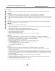
Important Safety Notice READ AND SAVE THESE INSTRUCTIONS www.zephyronline.com WARNING TO REDUCE THE RISK OF FIRE OR ELECTRIC SHOCK, DO NOT USE THIS FAN WITH ANY SOLID-STATE CONTROL DEVICE. WARNING TO REDUCE THE RISK OF FIRE ELECTRIC SHOCK, OR INJURY TO PERSONS, OBSERVE THE FOLLOWING: a. Use this unit only in the manner intended by the manufacturer, if you have questions, contact the manufacturer. b.
TO REDUCE THE RISK OF FIRE, USE ONLY METAL DUCTWORK. NOT FOR USE IN OUTDOOR COOKING ENVIRONMENTS. CAUTION To reduce risk of fire and to properly exhaust air outside - Do not vent exhaust air into spaces within walls, ceilings, attics, crawl spaces or garages. OPERATION Always leave safety grilles and filters in place. Without these components, operating blowers could catch onto hair, fingers and loose clothing.
List of Materials www.zephyronline.
Equivalent number length x used = Duct pieces Total Total 3-1/ 4” x 10” 1 Ft. Rect., straight x( ) = Ft. 6”- 8” Round 30 Ft. wall cap with damper x( ) = Ft. 7” Round, straight 1 Ft. x( ) = Ft. 6”- 8” Round, 30 Ft. roof cap x( ) = Ft. 8” Round, straight 1 Ft. x( ) = Ft. 6” round to 1 Ft. 3-1/ 4” x 10” rect. transition x( ) = Ft. 3-1/ 4” x 10” 15 Ft. Rect. 90 0 elbow x( ) = Ft. x( ) = Ft. 3-1/ 4” x 10” 9 Ft. Rect. 45 0 elbow x( ) = Ft. 6” round to 16 Ft.
Installation – Mounting Height & Clearance www.zephyronline.com ALWAYS, when possible, reduce the number of transitions and turns. If a long duct run is required, increase duct size from 8” to 10”. If turns or transitions are required: Install as far away from duct opening and as far apart between the two transitions as possible. A n. mi . B n mi . C x ma D n. mi . E n mi . F x ma Minimum mount height between range top to hood bottom should be no less than 26”.
NEVER exhaust air or terminate duct work into spaces between walls, crawl spaces, ceiling, attics or garages. All exhaust must be ducted to the outside, unless using the recirculating option. Use single wall rigid Metal ductwork only. Fasten all connections with sheet metal screws and tape all joints w/ certified Silver Tape or Duct Tape.
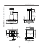
Installation – Hood Specifications www.zephyronline.com 12 15/16” 12 3/4” 8 1/4” Z1C-00VN min. ducted - 42” min. recirc. - 46 1/2” max. - 80 1/2” 2 11/16” 14 3/16” 11 1/16” STANDARD min. ducted - 28 1/2” min. recirc. - 32” max.
PAPER TEMPLATE Front of Hood C/ L A Cut-Out Shaded Area Ceiling Joists Wood Blocking 1 fron t 3 Top Support Frame B 2 FIG. B Bottom Support Frame 6 5 Hood Body/Canopy 4 FIG. A Hood is intended to be mounted to a finished ceiling. 1. Ceiling Preparation: Determine hood mounting location and temporarily tape paper template (incluided with the hood) to the ceiling. Cut-out internal shaded area of template to allow the ductng and electrical to pass through. Add wood blocking (min.
Installation – Mounting the Hood www.zephyronline.com FIG. C FRONT FIG. D FRONT 3. Hood heights between 40” to 50” require lateral support brackets to be installed to the two top support frame cut off arms and their corresponding bottom support frame arms. Install lateral support brackets by (12) M4 x 8 sheet metal screws. (FIG. C) 1 2 4. Hood heights between 45” to 50” require a square support bracket to be installed inside the support frame.
ELECTRONICS MOUNTING BRACKET 1 1 2 FIG. F FIG. H 7. Remove tape securing electronics mounting bracket to hood. (FIG. F, #1) Position electronics mounting bracket as show in (FIG. F, #2) and secure to hood body using (3) M4 x 8 truss head sheet metal screws. 8. Lift hood body and align the (4) pre-installed mounting screws on top of blower housing (FIG. A, #5 on Page 9) with the (4) key holes on the bottom of the support frame. (FIG. H) Slide hood towards the narrow end of key holes to lock in place.
Installation – Mounting the Hood www.zephyronline.com cut trim piece if necessary 1 Top support frame Top duct covers 2 5 Thick trim piece (top) 4 Thin trim piece (bottom) Bottom duct covers 3 Bottom support frame FIG. J 11. *Secure top duct covers (with louver holes) to top support frame using (2) M4 x 8 truss head sheet metal screws. (FIG. J, #1). Note: If using hood in “ducted mode” the top duct covers may be turned upside-down to hide the louver holes. 12.
We recommend to ALWAYS exhaust air outside of the home by employing existing or installing new duct work, if possible. The hood is most effective and efficient as an exhaust hood. Only when the exhaust option is not possible should you recourse to converting the hood into a recirculating hood. When converted to be a recirculating hood, a set of charcoal filters are required on top of its standard Aluminum Mesh Filter set. Order according to its Part number below.
Features & Controls - Touch Controls www.zephyronline.com Power / Delay Off 5 Display (speed level, delay off, filter clean/change,clean air) Lighted Glass Button clean mesh filter clean air replace charcoal filter Lights On/Dim/Off Adjust 6 Speed Levels 1 Power / Delay Off Button Power Button Function - Button will turn power on and off for entire hood (fan and lights). - Hood will remember the last speed and light level it was turned off at.
Charcoal Filter Replace Indicator (disabled by default, must be enabled if recirculating hood) - To enable Charcoal Filter Replacement Function: - With hood off, hold Button and Button simultaneously for three seconds. The Graphic will illuminate for three seconds indicating the Charcoal Filter Replacement Function is enabled. - To disable Charcoal Filter Replacement Function: - With hood off, hold Button and Button simultaneously for three seconds.
Maintenance – Hood and Filter Cleaning www.zephyronline.com SURFACE MAINTENANCE: Clean the hood surface periodically with hot soapy water and clean cotton cloth. Do not use corrosive or abrasive detergent, or steel wool/scouring pads which will scratch and damage surface. For heavier soil use liquid degreaser. After cleaning it is recommended that you use non-abrasive stainless steel polish/cleaners, to polish and buff out the stainless luster and grain.
Issue Cause What to do After installation, the unit doesn’t work. 1. The power source is not turned ON. 1. Make sure the circuit breaker and the unit’s power is ON. 2. The power line and the cable locking connector is not connecting properly. 2. Check the power connection with the unit is connected properly. 3. The wires on the control board are loose. 3. Make sure the wires on the control board are connected properly. 4. The switch board and control board wirings are disconnected. 4.
Fan Curve Diagrams www.zephyronline.com Airflow Control Technology (ACT) Some local codes limit the maximum amount of CFM a range hood can move. ACT allows you to control the maximum blower CFM of hoods with Zephyr’s DCBL Suppression System without the need for expensive make up air kits. ACT enables the installer to easily set the maximum blower speed to one of three most commonly specified CFM levels; 590, 440 or 290 CFM. The usage of ACT may not be necessary for your installation.
19 Fan Curve Diagrams
Wiring Diagram www.zephyronline.com Power consumption shown for default 715 CFM blower configuration ACT 590 CFM - Fan Max. 130W @ 1.8A ACT 390 CFM - Fan Max. 70W @ 1A ACT 290 CFM - Fan Max. 35W @ .
PART# Replacement Parts Light Bulb, LED 3W Z0B-0032 Aluminum Mesh Filter 50200049 Optional Accessories Recirculating Kit ZRC-00VN Replacement Charcoal Filter Z0F-C002 Duct Cover Extension (up to 12’ ceiling) Z1C-00VN To order parts, visit us online at http://store.zephyronline.com or call us at 1.888.880.
STAPLE YOUR RECEIPT HERE Proof of the original purchase date is needed to obtain service under warranty Limited Warranty TO OBTAIN SERVICE UNDER WARRANTY OR FOR ANY SERVICE RELATED QUESTIONS, please call: 1-888-880-8368 Zephyr Corporation (referred to herein as “we” or “us”) warrants to the original consumer purchaser (referred to herein as “you” or “your”) of Zephyr products (the “Products”) that such Products will be free from defects in materials or workmanship as follows: Three Year Limited Warranty
Guide d’utilisation, d’entretien et d’installation www.zephyronline.com Verona Island ZVN-M90AG ZVN-E42AG Numéro de modèle : _________________ Numéro de série : _________________ + SEP13.
www.zephyronline.
INSTALLATION Feuille de calcul pour le conduit ........................... Espace libre et hauteur de montage ................... Options d’installation pour le conduit .................. Spécifications de la hotte......................................... Montage de la hotte ................................................... Reprise d’air sans conduit ....................................... 5 6 7 8 9-12 13 COMMANDES Commandes à effleurement .................................. 14 Interface utilisateur ......
Mise en garde de sécurité LISEZ ET CONSERVEZ CES INSTRUCTIONS www.zephyronline.com AVERTISSEMENT POUR RÉDUIRE LES RISQUES D’INCENDIE OU DE DÉCHARGE ÉLECTRIQUE, N’UTILISEZ PAS CET APPAREIL AVEC UN TABLEAU DE COMMANDE À SEMI-CONDUCTEURS. AVERTISSEMENT POUR RÉDUIRE LES RISQUES D’INCENDIE, DE DÉCHARGE ÉLECTRIQUE OU DE BLESSURE, RESPECTEZ CES CONSIGNES : a. N’utilisez cet appareil que de la manière prévue par le fabricant. Si vous avez des questions, communiquez avec le fabricant. b.
POUR RÉDUIRE LES RISQUES D’INCENDIE, N’UTILISEZ QUE DES CONDUITS D’AÉRATION EN MÉTAL. CET APPAREIL N’EST PAS CONÇU POUR ÊTRE UTILISÉ À L’EXTÉRIEUR. ATTENTION Pour réduire les risques d’incendie et pour évacuer l’air convenablement, assurez-vous de canaliser l’air à l’extérieur de la maison. N’installez pas l’échappement du conduit dans les espaces entre les murs, le plafond, le grenier, les vides sanitaires ou le garage. FONCTIONNEMENT Laissez toujours les grilles de sûreté et les filtres en place.
Liste du matériel www.zephyronline.
Equivalent number length x used = Duct pieces Total Total 3-1/ 4” x 10” 1 Ft. Rect., straight x( ) = Ft. 6”- 8” Round 30 Ft. wall cap with damper x( ) = Ft. 7” Round, straight 1 Ft. x( ) = Ft. 6”- 8” Round, 30 Ft. roof cap x( ) = Ft. 8” Round, straight 1 Ft. x( ) = Ft. 6” round to 1 Ft. 3-1/ 4” x 10” rect. transition x( ) = Ft. 3-1/ 4” x 10” 15 Ft. Rect. 90 0 elbow x( ) = Ft. x( ) = Ft. 3-1/ 4” x 10” 9 Ft. Rect. 45 0 elbow x( ) = Ft. 6” round to 16 Ft.
Installation – Espace libre et hauteur de montage www.zephyronline.com La hauteur de montage minimale ne devrait pas être moins de 26”. La hauteur de montage maximale ne devrait pas outrepasser 34”. Il est important d’installer la hotte à la hauteur de montage adéquate.
N’évacuez ou ne terminez JAMAIS l’échappement du conduit dans les espaces entre les murs, les vides sanitaires, le plafond, le grenier, ou le garage. Tous les échappements doivent être dirigés à l’extérieur de la maison, à moins que l’option de reprise d’air ne soit utilisée. N’utilisez que des conduits en métal pour cloison simple. Fixez toutes les pièces du conduit avec des vis à tôle et isolez tous les joints avec du ruban adhésif en toile ou du ruban réflecteur certifié.
12 15/16” 12 3/4” 8 1/4” Z1C-00VN min. avec conduit - 42” min. avec reprise d’air - 46 1/2” max. - 80 1/2” 2 11/16” 14 3/16” 11 1/16” STANDARD min. avec conduit - 28 1/2” min. avec reprise d’air 32” max. - 50” 24” 16 3/4” 35 7/16”, 41 15/16” 27 7/16” CÔTÉ DEVANT 10 1/8” C/L 1 1/4” 4 13/16” C/L 71 5/1 6” 5/8” AC In 9 3/4” 10 15/16” C/L 4“ Installation – Spécifications de la hotte www.zephyronline.
GABARIT EN PAPIER Devant de la hotte Solives de plafond Bloc de bois 1 fron t 3 Cadre de fixation supérieur 2 FIG. B Cadre de fixation inférieur 6 5 Boîtier/pavillon de la hotte 4 FIG. A La hotte est conçue pour être installée à un plafond fini. 1. Préparation du plafond : Déterminez l’emplacement pour l’installation de la hotte et collez temporairement le gabarit en papier (inclus avec la hotte) au plafond. Dans le plafond, faites un trou correspondant à la zone interne ombragée du gabarit.
Installation – Montage de la hotte www.zephyronline.com FIG. C FRONT FIG. D FRONT 3. Des pattes de support latérales doivent être fixées aux deux bras du cadre de fixation supérieur et aux bras correspondants du cadre de fixation inférieur pour les hottes installées à une hauteur de 40 à 50 pouces. Fixez les pattes de support latérales à l’aide de douze vis à tôle M4 x 8. (FIG. C) 1 4. 2 FIG.
SUPPORT DE MONTAGE DU DISPOSITIF ÉLECTRONIQUE 1 1 2 FIG. H FIG. F 7. Enlevez le ruban qui retient le support de montage du dispositif électronique à la hotte (FIG. F#1). Enlevez les trois vis du dessus du boîtier de la hotte et laissez-les de côté. Placez le support de montage du dispositif électronique, comme illustré sur FIG. F#2 et fixez-le au boîtier de la hotte à l’aide des trois vis que vous avez préalablement enlevées. 8.
Installation – Montage de la hotte www.zephyronline.com Coupez la pièce d’habillage au besoin 1 Cadre de fixation supérieur Pièces de recouvrement supérieures 2 5 Pièce d’habillage large (haut) 4 Pièce d’habillage mince (bas) Pièces de recouvrement inférieures 3 Cadre de fixation inférieur FIG. J 11. *Fixez les pièces de recouvrement supérieures (avec les trous pour déflecteur) au cadre de fixation supérieur à l’aide de deux vis M4 x 8 (FIG. J#1).
Nous recommandons de TOUJOURS évacuer l’air à l’extérieur de la maison en utilisant le conduit en place ou, s’il y a possibilité, en installant un nouveau conduit. La hotte est plus efficace lorsqu’utilisée comme système d’évacuation d’air. Vous ne devriez recourir à la configuration de reprise d’air que lorsqu’il est impossible d’installer un conduit d’aération.
Commandes - Commandes à effleurement www.zephyronline.com Touche de mise en 5 Affichage (vitesse, arrêt automatique, nettoyage/changement marche/arrêt automatique des filtres, purification d’air) Touche de verre illuminé clean mesh filter clean air replace charcoal filter Lumières : Allumer/ Veilleuse/Éteindre Choix de six vitesses 1-Touche de mise en marche/arrêt automatique Fonction de mise en marche - La touche permet d’allumer et d’éteindre la hotte (ventilateur et lumières).
Indicateur de remplacement du filtre à charbon (désactivé par défaut, doit être activé avec le mode de reprise d’air) - Pour activer la fonction de remplacement du filtre à charbon : - Lorsque la hotte est éteinte, appuyez et tenez simultanément les touches et pendant trois secondes. Le symbole s’illumine pendant trois secondes, indiquant que la fonction de remplacement des filtres est activée.
Entretien - Nettoyage de la hotte et des filtres www.zephyronline.com ENTRETIEN DES SURFACES: Nettoyez régulièrement les surfaces de la hotte avec de l’eau savonneuse chaude et un chiffon de coton propre. N’utilisez pas de détergent abrasif ou corrosif, de laines d’acier ou de tampons à récurer; ils égratigneront et endommageront les surfaces. Pour les taches plus tenaces, utilisez du produit dégraissant liquide.
Problème Cause Solution Après l’installation, l’appareil ne fonctionne pas. 1. Le bloc d’alimentation n’est pas allumé 1. Assurez-vous que l’alimentation du disjoncteur et de l’appareil est allumée 2. La ligne électrique et le raccord de câble ne sont pas correctement branchés 2. Vérifiez que le branchement de l’appareil a été fait correctement 3. Les fils électriques du tableau de contrôle et de commande sont débranchés 3.
Tableau De Rendement Du Ventilateur www.zephyronline.com Débit d’air contrôle de la technologie (ACT) Certains codes locaux de limiter le montant maximum de CFM qu’une hotte de cuisinière peut se déplacer. ACT vous permet de contrôler le maximum CFM de les hottes avec le système de répression DCBL à partir de Zephyr sans avoir besoin de coûteux kits pour l’air de remplacement.
Debit (pi3/min) 19 Tableau De Rendement Du Ventilateur Pression (en TQ) Courbe de rendement du ventilateur, 390 CFM Entree en CA: 120V, 60 Hz Diametre du conduit de sortie : 8”
Schéma de câblage Consommation montré pour défaut de configuration du ventilateur 715 CFM ACT 590 CFM - Ventilateur Max. 130W @ 1.8A ACT 390 CFM - Ventilateur Max. 70W @ 1A ACT 290 CFM - Ventilateur Max. 35W @ .
Pièces de remplacement Ampoule DEL 3W Filtre à tamis en aluminium Z0B-0032 50200049 Accessoires optionnels Ensemble de reprise d’air Filtre à charbon de remplacement Ensemble de prolongement de recouvrement de conduit (Pour des plafonds allant jusqu’à 12 pieds) ZRC-00VN Z0F-C002 Z1C-00VN Pour commander des pièces, visitez-nous en ligne au www.zephyronline.
AGRAFEZ VOTRE REÇU ICI Garantie limitée Une preuve de la date d’achat originale est nécessaire pour obtenir du service lorsque le produit est sous garantie POUR OBTENIR DU SERVICE SOUS GARANTIE OU POUR TOUTE QUESTION LIÉE À L’ENTRETIEN, veuillez communiquer avec nous au 1-888-880-8368 Zephyr Corporation (désigné aux présentes sous le nom de « nous ») garantit au premier acheteur (désigné aux présentes sous le nom de « vous » ou « votre ») de produits Zephyr (les « Produits ») que lesdits produits sont ex