
Data Sheet
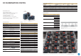


DC subminiature switch
Sealed switch IP67 protection
∙ Models available for 120°C operating temperature
∙ Nominal currents from 10A at 250 V AC
∙ Various auxiliary actuators available
(can also be retrofi tted)
∙ Various application-specifi c contact materials
∙ Mechanical operating life min. 1,000,000 operations
∙ Various terminal types available
DC SUBMINIATURE SWITCH
• Not every confi gurable variant is available for order. Please contact us.
• The fi nal two digits of article numbers on commercial documents refer to the
index of the respective drawing.
• Customer-specifi c models are marked with a G or W as the sixth digit of the
article number.
Technical specifi cations
Series
DC
❶
Contact confi guration S.P.D.T., S.P.S.T. - N.O., S.P.S.T. - N.C.
Contact gap < 3mm (μ)
Switching voltage (max.) 250V AC
Switching current 0.1 to 10AAC (see table on page 24)
depending on model
Operating voltage 200 to 340cN without auxiliary actuator,
depending on model
Total travel Approx. 1.6mm
Mechanical life (see table on page 23)
Electrical life
(see table on page 23)
Ambient temperature – 40 to + 85°C/120°C
Model with leads – 40 to + 105°C
Proof tracking index PTI175, PTI250 on request
Materials
Cover PBT (UL 94V-0), PET (UL 94V-0)
Actuator POM UL 94 HB (T85),
PBT UL 94 V-0 (T120)
Base PET (UL 94V-0)
Contacts AgNi/AuAgPt (Crosspoint)
Terminals CuZn silver-plated
Auxiliary actuator Stainless steel or Plastic
Sealing gasket VMQ
Leads Cu, PVC-sheated
Approvals
depending on model
Degree of protection
Switch interior
IP67
Circuitry ❸
Operating temperature +85°C Code
S.P.S.T. - N.O. E
S.P.S.T. - N.C. F
S.P.D.T. G
Operating temperature 120°C (with leads 105°C)
S.P.S.T. - N.O. A
S.P.S.T. - N.C. B
S.P.D.T. C
Electrical rating and operating life ❷
Electrical rating
according to
Electrical life at rated load
(operations)
Mechanical
life
Operating
force
Housing
mark
Code
EN 61058-1 UL 1054 acc. to EN acc. to UL max. (cN)
6A 250V AC 5A 125 – 250V AC 10,000 6,000 1 x 10
6
200 DC 1 1
10 (1.5)A, 250V AC 10.1A, 125 – 250V AC
1/4 HP, 125V AC
10,000 6,000 1 x 10
6
340 DC 2 2
0.1A, 250V AC 0.1A 125 – 250V AC 50,000 100,000 1 x 10
6
200 DC 3 3
3A, 250V AC 3A, 125 – 250V AC 50,000 6,000 1 x 10
6
200 DC 4* 4*
* only possible as line version with line diameter 0.5 mm
2
and AWG 22
Terminal type ❹
Model Code
Solder terminal short* A1
PCB terminal 1.3 x 0.5mm, straight* H1
PCB terminal 0.6 x 0.5mm, straight* K1
PCB terminal 0.6 x 0.5mm RH side** K8
PCB terminal 0.6 x 0.5mm LH side** K9
PCB terminal 0.6 x 0.5mm RH side*** K6
PCB terminal 0.6 x 0.5mm LH side*** K7
Q.C. terminal 2.8 x 0.5mm, straight* L1
Leads 0.5mm
2
, routed downwards B5
Leads 0.5mm
2
, with leads B3
Leads 0.5mm
2
, on side opposite actuator B4
Leads 0.75mm
2
, routed downwards C5
Leads 0.75mm
2
, with leads C3
Leads 0.75mm
2
, on side opposite actuator C4
Without leads (Form B), on side opposite actuator/
on actuator side*
N3/N4
Without leads (Form A), on side opposite actuator/
on actuator side*
P3/P4
Without leads (no cut-out), with solder terminal* Q5
* Max. 30° twisted ** with location pin *** W/o location pin
Generation of order code (example)
The order code consists of 5 parameters:
❶❷❸❹❺
Series Electrical rating Circuitry Terminal type Auxiliary actuator
DC
= subminiature
switch
1
= 6A, 250V AC
C
= S.P.D.T.
A1
= Solder terminal
short
LB
= Lever straight,
4.8
Auxiliary actuator ❺
Model Length Code
Without lever – AA
Straight 4.8 LB
8LC
42 LD
Roller 2.5 RB
4.7 RC
39.7 RD
Simulated roller 2.5 SB
4.7 SC
39.7 SD
Plastic, straight 7 WB
14 WC
Plastic roller 5.2 ZB
Plastic simulated roller 5.6 VB
For detailed information please note the technical specifi cations which you can fi nd in the download section of our website www.switches-sensors.zf.com.