
Data Sheet

D4 miniature switch
Versatile miniature snap action microswitch. A wide
variety of auxiliary actuators and terminal options are avail-
able as standard and the switch fulfi ls the requirements of
IEC603351: GWFI at 850°C, GWIT at 775°C and GWT750°C.
∙ High proof tracking index PTI 600
∙ High level of repeat accuracy
∙ High contact stability through application-specifi c contact
materials up to a switching current of 0.1 to 21A at 250V AC
∙ Ambient temperature – 40 to + 150°C
∙ Approved according to IEC 61058-1 / UL 61058-1
D4 MINIATURE SWITCH
Technical specifi cations
Series
D4
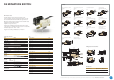
❶
Contact confi guration S.P.D.T., S.P.S.T. - N.O., S.P.S.T. - N.C.
Contact gap < 3mm (μ)
Switching voltage 250V AC
Switching current < 0.1 to 21A, depending on model
Total travel 2.6mm
Mechanical life see table on page 12
Electrical life see table on page 12
Ambient temperature 40T85; 40T125; 40T150
Proof tracking index PTI 300 (PET)/PTI 600 (PA6)
Materials
Housing/cover PET/PA6 (UL 94V-0)
Actuator POM (max. 85°C)
alternative PET (UL 94V-0)
Contact D41
materials D42
D43 – D48
AuAgPt (Crosspoint)
Ag
AgNi
Terminals CuZn, alternative Cu
Auxiliary actuator Nickel-plated steel,
alternative stainless steel
Approvals
Degree of protection
Switch interior
IP40
Circuitry ❸
Circuitry 40T85 Code
Standard operating force
S.P.S.T. - N.O. 1
S.P.S.T. - N.C. 2
S.P.D.T. 3
Light operating force Code
S.P.S.T. - N.O. 7
S.P.S.T. - N.C. 8
S.P.D.T. 9
Circuitry 40T125 Code
Standard operating force
S.P.S.T. - N.O. G
S.P.S.T. - N.C. H
S.P.D.T. M
Light operating force Code
S.P.S.T. - N.O. N
S.P.S.T. - N.C. P
S.P.D.T. R
Circuitry 40T150* Code
Light operating force
S.P.S.T. - N.O. S
S.P.S.T. - N.C. T
S.P.D.T. U
* Not for D48
13.3
15°
5°
2.7
15.1
55
14
5.64.4
207.8
1.8
4.3
1.8
20 7.8
5.6
4.3
4.4
519.5
7.65
1.6
5.75
1.8
5.65
5.6
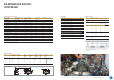
Mounting holes
Hole dimensions Measurement
„A“
Measurement
„B“
3.1± 0.15mm 3.3± 0.15mm
Q.C. terminal 6.3 x 0.8mm
straight
V1
Q.C. terminal 6.3 x 0.8mm
dog leg
V3
Solder terminal, short
B8
Solder terminal
with temperature-stop
S1
PCB terminal
1.3 x 0.8mm cover side
PB
PCB terminal
1.3 x 0.8mm housing side
PA
Q.C. terminal 4.8 x 0.8mm
dog leg
Q3
Q.C. terminal 4.8 x 0.8mm
straight
Q1
Q.C. terminal 4.8 x 0.5 mm
dog leg
R3
PCB terminal
1.3 x 0.5mm, underside
P4
Other terminals
available onrequest.
Q.C. terminal
RAST 2.5
X5
Q.C. terminal 6.3 x 0.8mm
RAST 5
Y5
Connector housing for
Q.C. terminal
6.3 x 0.8mm, RAST 5
Dimensions in mm
Terminals
27.8
22.2
20.25 2.8
A
10.3
4.1
A
SP
RS
10.32.8
B
13.1
14.7 ± 0.5
max. 16.2
Drilling patterns for PCB terminals
10
13.2
4.6
3.25
3.4
Ø 2
3.5
2.15
2.9
3.3
2.5
19.5
5
7.15
6.6
Ø 2.2
For detailed information please note the technical specifi cations which you can fi nd in the download section of our website www.switches-sensors.zf.com.