Villa Door Station User’s Manual V1.0.
Foreword General This manual introduces basic operations of the digital door station (hereinafter referred to as "VTO"). Safety Instructions The following categorized signal words with defined meaning might appear in the manual. Signal Words Meaning DANGER Indicates a high potential hazard which, if not avoided, will result in death or serious injury. WARNING Indicates a medium or low potential hazard which, if not avoided, could result in slight or moderate injury.
jurisdictions. For detailed information, see the paper user’s manual, use our CD-ROM, scan the QR code or visit our official website. The manual is for reference only. Slight differences might be found between the electronic version and the paper version. All designs and software are subject to change without prior written notice. Product updates might result in some differences appearing between the actual product and the manual.
Important Safeguards and Warnings This section introduces content covering the proper handling of the device, hazard prevention, and prevention of property damage. Read carefully before using the device, comply with the guidelines when using it, and keep the manual safe for future reference. Operation Requirements ● ● ● ● ● Check whether the power supply is correct before use. Do not unplug the power cord on the side of the device while the adapter is powered on.
Table of Contents Foreword .................................................................................................................................................... I Important Safeguards and Warnings .................................................................................................... III 1 Initializing the VTO ................................................................................................................................ 1 2 Login and Resetting Password...........
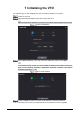
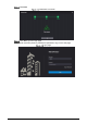
1 Initializing the VTO For first-time login or after resetting the VTO, you need to initialize it on the web. Power on the VTO. Go to the default IP address (192.168.1.108) of the VTO. Make sure that the IP address of your PC is in the same network segment as the VTO. Device initialization On the Device Init page, enter and confirm the password, and then click Next.
Click Next. Initialization successful Click OK to go to the login page. Enter username (admin by default) and password to log in to the web page.
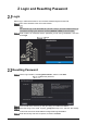
2 Login and Resetting Password Login Before login, make sure that the PC is in the same network segment as the VTO. Go to the IP address of the VTO in the browser. For first-time login, enter the default IP (192.168.1.108). If you have multiple VTOs, we recommend changing the default IP address (Network > Basic) to avoid conflict. Enter "admin" as username and the password you set during initialization, and then click Login.
If you did not set an email address during initialization, contact your supplier or customer service for help. The security code will be valid only for 24 hours upon receipt. If you enter the wrong security code for 5 consecutive times, your account will be locked for 5 minutes. Enter and confirm the new password, and then click OK.
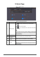
3 Home Page Home Page Table 3-1 Home page introduction No. Function Description : Change the password and your email address. : Go to the home page. 1 General function : Log out, restart the VTO or restore the VTO to factory settings. If you restore the VTO to factory settings, all data except external storage will be deleted. You can format the SD card to delete the data in it. 2 VTO information 3 System information 4 Configuration manager View the information of the VTO and the system.
4 Local Settings This chapter introduces the detailed configuration of the VTO. Slight differences might be found in different models. Basic Device Properties & Events Select Local Settings > Basic. Configure the parameters. Basic Table 4-1 Basic parameter description Parameter Description Device Type Select Villa Station or Small Apartment as needed. Center Call No. The default phone number for the management center is 888888, and you can set it to any number with up to 9 digits.
Parameter Description The number cannot be changed when the VTO serves as the SIP server. Periods in which Calls can be Made Configure the time if you only want to receive calls from VTH during a specific period. Group Call Enable it on the VTO that works as the SIP server, and when a main VTH receives a call, all extension VTHs will also receive the call. Storage Point SD card by default. Total SD Card Capacity SD Used Capacity Displays the total and used capacity of the SD card.
Count Click on the white module, and select the room number from the Room List you want to bind. White module Room list Click Save to save the selected room number.
Click Confirm to save all the settings. Confirm Video & Audio Configure the video format and quality, and audio of the VTO. Select Local Settings > Video & Audio.
Configure the parameters, which will take effect upon change. Table 4-2 Video parameter description Parameter Main Stream Description Video Format Select different resolution as needed: 720P: 1280 × 720. WVGA: 800 × 480. D1: 720 × 480. CIF: 352 × 288. Frame Rate The range is 1 to 25. The larger the value, the smoother the video, but it requires more bandwidth. Bitrate Rate Include 768 Kbps, 896 Kbps, 1024 Kbps, 1.25 Mbps, 1.5 Mbps, 1.75 Mbps, 2Mbps and 4 Mbps.
Parameter Description the light sensor, and we recommend keeping it default. Saturation The larger the value, the thicker the color. Gamma Changes the picture brightness and improves the picture dynamic range in a non-linear way. The larger the value, the brighter the image. Gain Adjustment Amplify the video signal to increase image brightness. If the value is too large, there will be more noise in the image. Mirror Display the image with left and right side reversed.
Local Configure the parameters. Table 4-3 Local access control parameter description Parameter Description Unlock Responding Interval The door can only be unlocked again after the interval. Unlock Period The time during which the lock stays unlocked. Check Door Signal Before Lock Select On or Off as needed. Door Sensor Check Duration If the door is unlocked longer than the Door Sensor Check Duration, the door sensor alarm will be triggered, and the alarm will be sent to the management center.
Lock connected through the RS-485 port Table 4-4 RS-485 description Parameter Description Interface Type Lock by default. Unlock Responding Interval The door can only be unlocked again after the interval. Unlock Period The time during which the lock stays unlocked. Second Unlock Command You can connect a third-party phone, such as a SIP phone, to the VTO, and use the command to open the door remotely. The default command is 456. Local: local lock. Second lock: 485 lock.
Table 4-5 System parameter description Parameter Description Date Format Select from one of the following: YYYY-MM-DD MM-DD-YYYY DD-MM-YYYY Time Format Select from one of the following: 24-Hour 12-Hour System Time Changing system time might cause problems on video searching and information publication. Turn off video recording and auto snapshot before changing it. Time Zone Configure the time zone as needed. Sync with PC Synchronize the VTO system time with your PC.
Configure functions that involve device security. Select Local Settings > Security. Security Configure the parameters. Table 4-6 Security parameter description Parameter Description Enable the use of CGI command. CGI Enable We recommend you turn it off. Otherwise, the VTO might be exposed to security risks and data leakage. Send information to the app on the smartphone. Mobile Push Notification Password Reset We recommend you turn it off if you do not need this function.
Parameter Description Protect your passwords. Outbound Service Information Protection We recommend you turn it on. Otherwise, the VTO might be exposed to security risks and data leakage. Enable it and the VTO will be found by other devices. Multicast/Broadcast Search We recommend you turn it off. Otherwise, the VTO might be exposed to security risks and data leakage. Security Mode (recommended): Support logging in with Digest authentication. Compatible Mode: Use the old login method.
Add an ONVIF user Enter the information, and then click Save. ONVIF devices can now monitor the VTO by using the account. Update Select Local Settings > Update. Select ways to check the update. Auto Check: Select the function to check automatically whether there is a new system version. Manual Check: Select the function to check whether there is a new system version. Update Upload File Upload audio file to change the sound when calling, unlocking the door, and more.
Change the sound prompt Click Upload. Legal Info You can view software license agreement, privacy policy, open source software notice in this section.
5 Household Setting This chapter introduces how to add, modify, and delete VTO, VTH, VTS, and IPC, and how to send messages from the SIP server to VTOs and VTHs when the VTO works as the SIP server. If you are using other servers as the SIP server, see the corresponding manual for details. VTO No. Management You can add VTOs to the SIP server, and all the VTOs connected to the same SIP server can call each other. Log in to the web page of the VTO that works as the SIP server.
The SIP server must be added. Table 5-1 Add VTO configuration Parameter Description No. The VTO number you configured. Registeration Password Leave it as default. Build No. Available only when the platform servers work as the SIP server. Unit No. IP Address IP address of the VTO. Username Username and password used to log in to the web page of the VTO. Password Click Save.
Add a room number Configure the parameters. Table 5-2 Room information Parameter Description First Name Last Name Enter the information you need to differentiate each room. Nick Name Enter a room number, and then configure the number on a VTH to Room No. connect to connect it to the network. Registeration Type Select public. Registeration Password Leave it as default. Click Save. Click or to modify or delete a room number. Personnel Management Adding personnel information.
Personnel management Click Add. Add personnel information Enter the parameters, and then click Save. The personnel information displays on the web page. For some VTO models, the QR code is embedded in the Personnel Management page. Yet for some models, you need to go to Network > Basic > Cloud Service to check the QR code. Operation succeed Select to go to the card issuing window.
Card issuing window Click Issue Card to issue cards. The web page displays the countdown prompt (120 s). Once the countdown starts, you need to swipe the card on the card reader of the VTO within this time period. After the swiping, the card number will be automatically recognized by the VTO. Countdown in process Click Confirm Send Card after swiping to complete the issuing process.
Other Operations Click to set it to loss, and then the icon changes to . The lost card cannot be used to open the door. Click or to modify the username or delete the card. VTS Management You can add a VTS to the SIP server, and then it can be used as the management center. It can also manage, call, or receive calls from all the VTOs and VTHs in the network. See the corresponding user's manual for details. Log in to the web page of the VTO that works as the SIP server.
Table 5-3 Add VTS configuration Parameter Description VTS No. The number of the VTS. Registeration Password Leave as default. IP Address VTS IP address. Click Save. Status You can view the online status and IP addresses of all the connected devices. Log in to the web home page of the SIP server, and then select Household Setting > Status.
6 Network This chapter introduces how to configure the network parameters. Basic 6.1.1 TCP/IP You need to configure the TCP/IP information to connect the VTO to the network. The descriptions below are for models with a Wireless LAN card. A Wireless LAN device is optional. Wireless LAN Log into the VTO web page. Select Network > Basic. Configure the TCP/IP parameters in the WLAN section. LAN Log into the VTO web page. Select Network > Basic. Configure the TCP/IP parameters in the LAN section.
Port Table 6-2 Parameter description Parameter Description Port 80 by default. If already used, choose any number from 1025 to 65535 as needed. You can enter http://VTO IP address: Port to log in to the VTO. HTTPS Port Enable it and click Save. You can now enter https://VTO IP address: HTTPS Port to log in to the VTO. TCP/UDP Port Used for accessing the VTO with devices in other networks. See "6.2 UPnP" for details.
For some VTO models, the QR code is embedded in the Cloud Service module. Yet for some models, you need to go to Household Setting > Personnel Management to check the QR code. UPnP When the VTO works as the SIP server, you can configure the UPnP function to allow WAN devices to log in to the VTO. UPnP Preparation Enable the UPnP function on the router, and then configure a WAN IP address for the router. Connect the VTO to the LAN port of the router. 6.2.
Add a UPnP service Table 6-3 Parameter description Parameter Description Service Name Service Type Enter the information as needed. Protocol Select TCP or UDP as needed. Internal Port Use port number from 1024 through 5000. External Port Do not use port number 1–1023 to avoid conflict. If you need to configure this function for multiple devices, make sure that the ports are not the same. The port number you use must not be occupied. The internal and external port number must be the same.
VTO as the SIP server Table 6-4 SIP server configuration (VTO as the SIP server) Parameter Description IP Addr. Your planned IP address of the VTO. Port 5060 by default when a VTO works as the SIP server. Username Leave it as default. Password SIP Domain Leave it as default. SIP Server Username Username and password used to log into the web page of the SIP server.
Parameter Description server. SIP Server Username/ Password Used to log in to the SIP server. The alternate server will be used as the SIP server when Express/DSS stops responding. We recommend you configure the alternate IP address. Alternate IP Addr. If you enable Alternate Server, the current VTO you have logged in serves as the alternate server. If you want another VTO serve as the alternate server, you need to enter the IP address of that VTO in the Alternate IP Addr. textbox.
Firewall Select Type, and then enable it. Configure the parameters. Click Confirm. Table 6-6 Firewall type description Type Description Network Access Select either Allowlist or Blocklist, and then add an IP address or segment which is allowed or denied to access the VTO. PING Prohibited The VTO will not response to ping to avoid ping attacks. Anti-semijoin Protects the VTO performance by blocking excessive SYN packets. Mode Allowlist: Devices that have been granted an access.
7 Log Management Select Search Log. You can search for different logs, and export them to your PC as needed. If storage is full, the oldest records will be overwritten. Back up the records as needed.
Unlock Log Select time range and type, and then you can see all the log information.
Cybersecurity Recommendations Mandatory actions to be taken for basic device network security: 1. Use Strong Passwords Please refer to the following suggestions to set passwords: The length should not be less than 8 characters; Include at least two types of characters; character types include upper and lower case letters, numbers and symbols; Do not contain the account name or the account name in reverse order; Do not use continuous characters, such as 123, abc, etc.
8. 9. 10. 11. 12. 13. We recommend you to bind the IP and MAC address of the gateway to the device, thus reducing the risk of ARP spoofing. Assign Accounts and Privileges Reasonably According to business and management requirements, reasonably add users and assign a minimum set of permissions to them. Disable Unnecessary Services and Choose Secure Modes If not needed, we recommend turning off some services such as SNMP, SMTP, UPnP, etc., to reduce risks.