IR Intelligent Speed Dome Installation Manual Version 1.0.
Table of Contents 1 INTELLIGENT SPEED DOME INSTALLATION PREPARATION...................... 1 1.1 Basic Requirement .............................................................................................................................. 1 1.2 Check installation space and installation location intension .................................................. 1 1.3 Please keep all package material well for future use .................................................................
8 APPENDIX Ⅳ WIRE GAUGE REFERENCE SHEET .......................................
Important Safeguards and Warnings Safety Measures 1. Qualified Engineer Needed The installation engineer or maintenance engineer shall have corresponding CCTV system installation certificate or maintenance qualification certificate. The installation engineer or maintenance engineer shall have qualification certificate for work at height.
Please select the proper speed dome installation mode and use the lifting appliances at the safety environment. The lifting appliances shall have the enough capacity to reach the installation height. The lifting appliances shall have safe performance. The precaution measures include two types: Warning and Note. Warning: It is to alert you there is an optional risk of death or series injury! Note: It is to alert you there is an optional risk of damage or property loss! Warning 1. 2. 3. 4.
We are not liable for any problems caused by unauthorized modifications or attempted repair. 4. Do not allow other object falling into the device Please make sure there is no metal or inflammable, explosive substance in the speed dome. The above mentioned objects in the device may result in fire, short-circuit or damage. Please shut down the device and disconnect the power cable if there is water or liquid falling into the camera. Please contact your local retailer ASAP.
1 vi
2 INTELLIGENT SPEED DOME INSTALLATION PREPARATION 2.1 Basic Requirement All installation and operation here should conform to your local electrical safety codes. Before installation, please open the package and check all the components are included. Please make sure the speed dome installation environment and installation mode can meet your requirement. If there is special requirement, please contact your local retailer for more information.
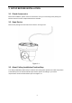
3 SETUP BEFORE INSTALLATION 3.1 Check Accessories Before the installation, please check the accessories one by one according to the packing list. Please make sure all the components listed are included. 3.2 Open Device Remove the package and then take out the device. See Figure 3-1. Figure 3-1 3.3 About Ceiling Installation Position Map The ceiling installation position map is to define hard ceiling holes position and cable exit position. The beeline part is the mechanical blind spot.
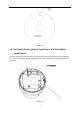
Figure 3-2 3.4 Dial Switch Setting (Analog Speed Dome, HDCVI Intelligent Speed Dome) Open the cover of the pedestal, then you can see there are two dial switches on the PTZ which are used to set terminal matched resistance.
Figure 2-4 120Ω terminal resistance is available on the power panel, different dial switch modes are consistent with corresponding terminal resistance access status, please see sheet 3-1 for more information. 1 2 Terminal Resistance Access Status OFF OFF OFF ON OFF ON OFF ON ON ON ON ON Sheet 3-1 3.5 TF Card Slot and Reset Button TF card slot and RESET button is shown as in Figure 3-5. Press the RESET button for at least five seconds; you can restore factory default setup.
4 CEILING INSTALLATION 4.1 Installation Components The ceiling installation dome body is shown as in Figure 4-1. Figure 4-1 4.2 Ceiling Installation Steps 4.2.1 Installation Requirements The ceiling mount speed dome can be installed in the hard construction wall in the indoor environments. Before the installation, please make sure: The wall is thick enough to install the expansion bolt. The wall can at least sustain the 8x weight of the speed dome. 4.2.
Figure 4-2 4) In Figure 4-3, line up the three quick installation screws at the bottom of the pedestal and the concave to the three holes and the U slot at the sheet metal respectively. Turn counter clockwise to secure the speed dome and the sheet metal closely. Note When the arrow of the ceiling installation position turns to the character “open” at the side of the speed dome, you can see the speed dome and then sheet metal are closely secured.
5 WALL MOUNT BRACKET INSTALLATION 5.1 Component Installation Wall mount bracket is shown as below. See Figure 5-1. Figure 5-1 5.2 Installation 5.2.1 Installation Requirements The wall mount speed dome can be installed in the hard construction wall in the indoor environments. Before the installation, please make sure: The wall is thick enough to install the expansion bolt. The wall can at least sustain the 8x weight of the speed dome. 5.2.2 Installation Steps 1).
Figure 5-2 2). Connect the hanging mount to the internal thread of the wall mount bracket. Secure screws to the right side of the wall mount bracket to secure the hanging mount. Please note this step is very important. Please make sure the screws are firm, otherwise, it may result in falling risk of the intelligent speed dome. Use three self-captive screws to secure the sheet metal on the hanging mount. See Figure 5-3.
wall mount bracket and pull it out of the other end of the wall mount bracket. Line up the three quick installation screws at the bottom of the pedestal and the concave to the three holes and the U slot at the sheet metal respectively. Turn counter clockwise to secure the speed dome and the sheet metal closely. See Figure 5-4.
Figure 5-5 10
6 APPENDIX Ⅰ LIGHTENING PROTECTION AND SURGE PROTECTION This series speed dome adopts TVS lighting protection technology. It can effectively prevent damages from various pulse signals below 4000W, such as sudden lighting and surge. While maintaining your local electrical safety code, you still need to take necessary precaution measures when installing the speed dome in the outdoor environment.
7 APPENDIX Ⅱ 24V AC WIRE GAUGE AND TRANSMISSION DISTANCE RELATIONSHIP SHEET It is the recommended transmission distance when the cable diameter is fixed and the 24V AC power consumption is below 10%. For the AC device, the max permission voltage power consumption is 10%. For example, when a device of rated power 20W installed 141 inches (42m) from the transformer, then the min cable diameter is 0.8000mm. mm Feet(m) 0.8000 1.000 1.250 2.000 w 5 10 15 20 25 30 35 40 45 50 55 60 65 70 75 80 85 90 95 100 488.
8 APPENDIX Ⅲ 12V DC WIRE GAUGE AND TRANSMISSION DISTANCE RELATIONSHIP SHEET The recommended max transmission distance is under the following environments: The wire diameter is fixed and the DC 12V power voltage loss rate is below 10%. For the device of DC power supplying, the max allowed voltage loss rate is 10%. All the wires listed in the following sheet are copper wire. (Copper wire resistance mm Feet(m) 0.8000 ) 1.000 1.250 2.
9 APPENDIX Ⅳ WIRE GAUGE REFERENCE SHEET Metric bare wire diameter (mm) 0.050 0.060 0.070 AWG SWG 43 42 41 47 46 45 Bare wire cross section (mm2) 0.00196 0.00283 0.00385 0.080 0.090 40 39 44 43 0.00503 0.00636 0.100 0.110 0.130 38 37 36 42 41 39 0.00785 0.00950 0.01327 0.140 0.160 35 34 37 0.01539 0.02011 0.180 0.200 0.230 33 32 31 35 0.02545 0.03142 0.04115 0.250 0.290 30 29 33 31 0.04909 0.06605 0.330 0.350 0.400 28 27 26 30 29 28 0.08553 0.09621 0.1257 0.450 0.
owners. • If there is any uncertainty or controversy, please refer to the final explanation of us. • Please visit our website or contact your local service engineer for more information. • This device complies with Part 15 of the FCC Rules. Operation is subject to the following two conditions: • (1) This device may not cause harmful interference, and • (2) This device must accept any interference received, including interference that may cause undesired operation.