Network Video Recorder User's Manual V2.0.
Foreword General This user’s manual (hereinafter referred to be "the Manual") introduces the installation, functions and operations of the Network Video Recorder (NVR) devices (hereinafter referred to be "the Device"). Read carefully before using the device, and keep the manual safe for future reference. Safety Instructions The following signal words might appear in the manual. Signal Words Meaning Indicates a high potential hazard which, if not avoided, will result in death or serious injury.
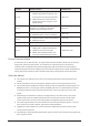
Version Revision Content Release Time ● Added picture search, picture search playback, disk health monitoring, and V1.0.6 V1.0.5 V1.0.4 V1.0.3 V1.0.2 exporting and importing face database. May 2020 ● Updated AI search, human detection, configuration of face recognition, and display settings. Added split tracking, main-sub tracking, analytics list, configuring video quality analytics, iSCSI, and cluster service. May 2020 ● Added 16 models. April 2020 ● Added PoE status, switch, and display.
● Please visit our website, contact the supplier or customer service if there is any problem occurred when using the device. ● If there is any uncertainty or controversy, please see our final explanation.
Important Safeguards and Warnings The following description is the correct application method of the device. Read the manual carefully before use to prevent danger and property loss. Strictly conform to the manual during application and keep it properly after reading. Operating Requirement ● Install the PoE front-end device indoors. ● The device does not support wall mount. ● Do not place and install the device in an area exposed to direct sunlight or near heat generating device.
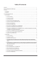
Table of Contents Foreword .............................................................................................................................................................I澳 Important Safeguards and Warnings............................................................................................................... IV澳 1 Features ........................................................................................................................................................... 1澳 1.
2.2.12 General 1U AI NVR Series ........................................................................................................... 34澳 2.2.13 Smart 1U 4PoE AI NVR Series .................................................................................................... 35澳 2.2.14 General 1U 4PoE AI NVR Series ................................................................................................. 35澳 2.2.15 Smart 1U 8PoE AI NVR Series ...................................................
3.5.5 Professional 4K 1U/ Professional 4K 1U with 8 PoE ports/ Professional 4K 1U with 16 PoE ports/4K 1U (S2) with 24 PoE Ports/4K 1U (S2E) with 8 PoE Ports/4K 1U (S2E) with 16 PoE Ports Series................................................................................................................................................ 81澳 3.5.6 General 4K 1U (S2)/4K 1U (S2) with 4 PoE ports/4K 1U (S2) with 8 PoE ports/4K 1U (S2) with 16 PoE ports Series .................................................
5.6.7.3 Configuring PTZ Functions ................................................................................................ 118澳 5.6.7.3.1 Configuring Presets ................................................................................................... 118澳 5.6.7.3.2 Configuring Tours ...................................................................................................... 118澳 5.6.7.3.3 Configuring Patterns .......................................................................
5.7.10.1 Device Status.................................................................................................................... 149澳 5.7.10.2 Firmware........................................................................................................................... 150澳 5.8 Recording Management ..................................................................................................................... 151澳 5.8.1 Recording Schedule ..............................................
5.9.5.5 AI Search (Face Recognition) ............................................................................................. 182澳 5.9.5.5.1 Search by Attributes .................................................................................................. 182澳 5.9.5.5.2 Search by Image ........................................................................................................ 184澳 5.9.5.5.3 Report Query ...............................................................................
5.9.10.2 Configuring Crowd Distribution ....................................................................................... 228澳 5.9.10.3 Report Query.................................................................................................................... 229澳 5.9.11 People Counting ....................................................................................................................... 229澳 5.9.11.1 Enabling Smart Plan ........................................................
5.10.7 Thermal Alarm .......................................................................................................................... 256澳 5.10.8 Exception .................................................................................................................................. 257澳 5.10.9 Disarming ................................................................................................................................. 258澳 5.11 Network...........................................
5.12.7 Record Estimate........................................................................................................................298澳 5.12.7.1 Calculating Recording Time ............................................................................................. 300澳 5.12.7.2 Calculating HDD Capacity for Storage ............................................................................. 300澳 5.12.8 FTP .......................................................................................
5.16.1 Display ...................................................................................................................................... 334澳 5.16.2 Tour ........................................................................................................................................... 335澳 5.16.3 Custom Layout ......................................................................................................................... 337澳 5.17 POS ........................................
6.2 Web Login ........................................................................................................................................... 365澳 6.3 Web Main Menu .................................................................................................................................. 366澳 7 Glossary ....................................................................................................................................................... 369澳 8 FAQ ......................
1 Features 1.1 Overview The NVR is a high performance network video recorder. This product supports local live view, multiple-window display, recorded file local storage, remote control and mouse shortcut menu operation, and remote management and control function. This product supports center storage, front-end storage and client-end storage. The monitor zone in the front-end can be set in anywhere.
● Smart search. It includes smart functions such as searching by attribute and searching by image to enable users to get target records quickly. Cloud Upgrade For the NVR connected to the Internet, it supports application online upgrade. Real-Time Surveillance ● VGA, HDMI port. Connect to monitor to realize real-time surveillance. Some series support TV/VGA/HDMI output at the same time. ● Shortcut menu for preview. ● Support multiple popular PTZ decoder control protocols.
Window Split Adopt video compression and digital processing to display several windows in one monitor. Support 1/4/8/9/16/25/36 window split in preview and 1/4/9/16 window split in playback. Record Support regular record, motion record, alarm record and smart record. Save the recorded files in the HDD, USB device, client-end PC or network storage server and you can search or playback the saved files at the local-end or via the Web/USB devices. Backup Support network backup and USB record backup.
2 Front Panel and Rear Panel The following front panel and rear panel figures are for reference only. 2.1 Front Panel 2.1.1 Smart 1U Series The figure is for reference only. The 4K Smart 1U (S2) front panel is shown as below. Figure 2-1 Front panel The 4K Smart 1U (S2) with 8 PoE ports/Beneficio 4K Smart 1U(S2) with 8 PoE ports front panel is shown as below.
Figure 2-2 Front panel Table 2-1 Icons No. Name Function 1 HDD status indicator light The red light becomes on when HDD is abnormal. 2 Power indicator light The red light becomes on when the power connection is normal. 3 Network status indicator light The red light becomes on when the network connection is abnormal. 2.1.2 Compact 1U Series The figure is for reference only.
Icon Name Function POWER Power status indicator light The blue light is on when the power connection is OK. USB port Connect to peripheral USB storage device, mouse and more. 2.1.3 1U/1.5U/2U Series The figures are for reference only. The 1U series front panel is shown as below. Figure 2-4 Front panel The 1.5U series front panel is shown as below.
2.1.4 Smart 1U 4K (S2) with Wireless Series The front panel is shown as below. The figure is for reference only. Figure 2-7 Front panel Table 2-4 Icons Icon Name Function HDD HDD status indicator light The blue light is on when the HDD malfunctions. NET Network status indicator light The blue light is on when the network connection is abnormal. PWR Power status indicator light The blue light is on when the power connection is normal. 2.1.
The figure is for reference only. Figure 2-8 Front panel Table 2-5 Icons Icon Name Function HDD HDD status indicator light The blue light is on when the HDD is malfunction. NET Network status indicator light The blue light is on when the network connection is abnormal. POWER Power status indicator light The blue light is on when the power connection is normal. USB 2.0 port Connect to peripheral USB storage device, mouse and more. 2.1.
Figure 2-9 Front panel The Smart 1U 4PoE AI NVR front panel is shown as below. Figure 2-10 Front panel The Smart 1U 8PoE AI NVR front panel is shown as below. Figure 2-11 Front panel 2.1.7 General 1U AI NVR Series The figure is for reference only. The General 1U AI NVR front panel is shown as below. Figure 2-12 Front panel Table 2-6 Icons Icon Name Function HDD status indicator light The blue light is on when the HDD malfunctions.
Icon Name Function USB 2.0 port Connect to peripheral USB 2.0 storage device, mouse, burner and more. 2.1.8 Compact 1U AI NVR/General 1.5U AI NVR Series The figure is for reference only. The Compact 1U AI NVR front panel is shown as below. Figure 2-13 Front panel The General 1.5U AI NVR front panel is shown as below. Figure 2-14 Front panel Table 2-7 Icons Icon Name Function HDD status indicator The blue light is on when the HDD malfunctions.
The figure is for reference only. Figure 2-15 Front panel Table 2-8 Icons Icon HDD Name Function HDD status indicator The blue light is on when the HDD malfunctions. light NET Network status indicator light The blue light is on when the network connection is abnormal. POWER Power status indicator light The blue light is on when the power connection is OK. USB 2.0 port Connect to peripheral USB 2.0 storage device, mouse, burner and more. 2.1.10 General 1U AI NVR/General 1.
Figure 2-17 Front panel Table 2-9 Icons Icon Name Function STATUS Status indicator light The blue light is on when the device is working properly. HDD/ HDD status indicator light The blue light is on when the HDD malfunctions. NET/ Network status indicator light The blue light is on when the network connection is abnormal. POWER/ Power status indicator light The blue light is on when the power connection is OK. USB 2.0 port Connect to peripheral USB 2.
2.1.12 Advanced 2U 32/64/128Channel AI NVR Series The following figures are for reference only. The Advance 2U 32Channel AI NVR front panel is shown as below. Figure 2-19 Front panel Table 2-11 Icons Icon Name Function STATUS Status indicator light The blue light is on when the device is working properly. HDD HDD status indicator light The blue light is on when the HDD malfunctions. NET Network status indicator light The blue light is on when the network connection is abnormal.
No. Icon Name 7 ALARM Alarm indicator light 2.1.13 Advanced 3U AI NVR Series The following figures are for reference only. For the product of LCD, the front panel of Advanced 3U AI NVR is shown as below. Figure 2-21 Front panel Table 2-13 Icons No. Name Function Press it once to turn on the device. Press it for a long time to turn off the device. 1 Power button We do not recommend you turn off the Device in this way.
Figure 2-22 Front panel Table 2-14 Icons No. Name Function Press it once to turn on the device. Press it for a long time to turn off the device. 1 Power button We do not recommend you turn off the Device in this way. Press power button for a long time or pull out the power cable might result in device auto restart. The blue light becomes on after system booted up properly. 2 System HDD Indicator light 3 Alarm indicator light The alarm indicator light becomes on once an alarm occurred.
Figure 2-23 Front panel 2.2 Rear Panel 2.2.1 Smart 1U Series The general is shown as below. Figure 2-24 Rear panel The 4 PoE ports appearance is shown as below. Figure 2-25 Rear panel The 8 PoE ports appearance is shown as below.
Figure 2-26 Rear panel Table 2-15 Ports Port Name Connection Function Power socket. / ● For general, input 12 VDC/2 A. Power input port ● For 4 PoE ports, input 48 VDC/1.25 A. ● For 8 PoE ports, input 48 VDC/2 A. Network port 10/100 Mbps self-adaptive Ethernet port. Connect to the network cable. USB port USB port. Connect to mouse, USB storage device and more. HDMI High Definition Media Interface High definition audio and video signal output port.
Figure 2-27 Rear panel The 4 PoE ports series rear panel is shown as below. Figure 2-28 Rear panel The 8 PoE ports series rear panel is shown as below. Figure 2-29 Rear panel Table 2-16 Ports Port Name / Connection Power input port Function Power socket. ● For general series, input 12 VDC/2 A. ● For 4 PoE ports series, input 48 VDC/1.25 A. ● For 8 PoE ports series, input 48 VDC/2 A. Network port 10/100 Mbps self-adaptive Ethernet port. Connect to the network cable. USB port USB port.
Port Name Connection Function Audio output port. It is to output the analog audio signal to the devices such as the sound box. MIC OUT Audio output port ● Bidirectional talk output. ● Audio output on 1-window video monitor. ● Audio output on 1-window video playback. GND Ground end. Built-in switch. Support PoE function. PoE PORTS PoE port For PoE series product, you can use this port to provide power to the network camera. 2.2.
Port Name Connection Function HDMI High Definition Media Interface High definition audio and video signal output port. It transmits uncompressed high definition video and multiple-channel data to the HDMI port of the display device. HDMI version is 1.4. VGA VGA video output port VGA video output port. Output analog video signal. It can connect to the monitor to view analog video. MIC IN Audio input port Bidirectional talk input port.
Figure 2-35 Rear panel The professional 4K 1U with 24 PoE ports series rear panel is shown as below. Figure 2-36 Rear panel The professional 4K 1U (S2E) with 8 PoE ports/4K 1U (S2E) with 16 PoE ports series rear panel is shown as below. The following figure takes 4K 1U (S2E) with 16 PoE ports series as an example. Figure 2-37 Rear panel Table 2-18 Ports Icon Port Name Function Network port 10/100/1000 Mbps self-adaptive Ethernet port. Connect to the network cable.
Icon Port Name Function ● There are two groups. The first group is from port 1 to port 4; the second group is from port 5 to port 8. They are to receive the signal from the 1–8 Alarm input port 1– 8 external alarm source. There are two types; NO (normal open)/NC (normal close). ● When your alarm input device is using external power, please make sure the device and the NVR have the same ground. GND Alarm input ground port. ● 3 groups of alarm output ports.
Figure 2-38 Rear panel The professional 4K 1.5U with 16 PoE ports / professional 4K 2U with 16 PoE ports series rear panel is shown as below. Figure 2-39 Rear panel The professional 4K 1U (S2) with 24 PoE ports series rear panel is shown as below. Figure 2-40 Rear panel The 4K 1.5U (S2E) with 16 PoE ports series rear panel is shown as below. Figure 2-41 Rear panel The 4K 2U (S2E) with 16 PoE ports series rear panel is shown as below.
Name Function Power input port Input 100–240 VAC. Network port 10/100/1000 Mbps self-adaptive Ethernet port. Connect to the network cable. eSATA port External SATA port. It can connect to the device of the SATA port. Please jump the HDD when there is peripheral connected HDD. USB port USB port. Connect to mouse, USB storage device, USB burner and more. HDMI High Definition Media Interface High definition audio and video signal output port.
Name Function A RS485_A port. It is the cable A. You can connect to the control devices such as speed dome PTZ. B RS-485 communication port RS485_B. It is the cable B. You can connect to the control devices such as speed dome PTZ. — Controller 12 V power output. It is to control the on-off alarm relay output. It can be used to control the device alarm output. At the same time, it can also be used as the power input source of some devices such as the alarm detector.
Figure 2-45 Rear panel The 4K 1U (S2) with 16 PoE ports series rear panel is shown as below. Figure 2-46 Rear panel Table 2-20 Rear panel description Name Function Power switch Power on/off button. Input 12 VDC/4 A. For general 4K 1U (S2) series product only. Switch power port. Input 48 VDC/96 W. For 4K 1U (S2) with 4 PoE ports series product only. Power input port Input 90~264-12 VAC 5 A/52 V 2.5 A-190 W. For 4K 1U (S2) with 8 PoE ports/ 4K 1U (S2) with 16 PoE ports series product only.
Name B Function port RS485_B. It is the cable B. You can connect to the control devices such as speed dome PTZ. Network port 10/100/1000 Mbps self-adaptive Ethernet port. Connect to the network cable. USB port USB port. Connect to mouse, USB storage device, USB burner and more. RS-232 RS-232 debug COM It is for general COM debug to configure IP address or transfer transparent COM data. HDMI High Definition Media Interface High definition audio and video signal output port.
Name Function Audio output port. It is to output the analog audio signal to the devices such as the sound box. MIC OUT ● Bidirectional talk output. Audio output port ● Audio output on 1-window video monitor. ● Audio output on 1-window video playback. VIDEO OUT Video output port CVBS output ● There are four groups. The first group is from port 1 to port 4, the second group is from port 5 to port 8, the third group is from 9 to 12, and the fourth group is from 13 to 16.
Name Function RS-232 RS-232 debug COM It is for general COM debug to configure IP address or transfer transparent COM data. HDMI High Definition Media Interface High definition audio and video signal output port. It transmits uncompressed high definition video and multiple-channel data to the HDMI port of the display device. HDMI version is 1.3. VGA VGA video output port VGA video output port. Output analog video signal. It can connect to the monitor to view analog video. Built-in Switch.
Name Function ● There are four groups. The first group is from port 1 to port 4, the second group is from port 5 to port 8, the third group is from 9 to 12, and the fourth group is from 13 to 16. They are to 1–16 Alarm input port 1– 16 receive the signal from the external alarm source. There are two types; NO (normal open)/NC (normal close). ● When your alarm input device is using external power, please make sure the device and the NVR have the same ground. GND Alarm input ground port.
Name Function VGA VGA video output port PoE PORTS PoE port VGA video output port. Output analog video signal. It can connect to the monitor to view analog video. Built-in Switch. Support PoE. For PoE series product, you can use this port to provide power to the network camera. 2.2.9 Smart 1U 4K (S2) with Wireless Series Figure 2-51 Rear panel Table 2-23 Ports Port Name Connection Function USB 2.0 port USB 2.0 port. Connect to mouse, USB storage device, USB burner and more.
Port Name Connection Function Power input port Input 12 VDC/2 A. Device Wi-Fi reset and WPS function button: ● Hold down this button for 5 seconds and above to restore Wi-Fi AP to defaults. WPS/RESET Reset/WPS function ● Press this button for less than 2 seconds, and then press the WPS button of Wi-Fi IPC, the device and Wi-Fi IPC can be connected. 2.2.
Icon Name Function HDMI High Definition Media Interface High definition audio and video signal output port. It transmits uncompressed high definition video and multiple-channel data to the HDMI port of the display device. HDMI version is 1.4. VGA VGA video output port VGA video output port. Output analog video signal. It can connect to the monitor to view analog video. GND Ground end.
Port Name Connection Function Network port 10/100 Mbps self-adaptive Ethernet port. Connect to the network cable. Power input port Power socket. GND Ground end. 2.2.12 General 1U AI NVR Series The rear panel is shown as below. The figure is for reference only. Figure 2-54 Rear panel Table 2-26 Ports Port Name Connection Function GND Ground end. USB port USB port. Connect to mouse, USB storage device and more.
2.2.13 Smart 1U 4PoE AI NVR Series The figure is for reference only. Figure 2-55 Rear panel Table 2-27 Ports Port Name Connection Function USB port USB port. Connect to mouse, USB storage device and more. HDMI High Definition Media Interface High definition audio and video signal output port. It transmits uncompressed high definition video and multiple-channel data to the HDMI port of the display device. HDMI version is 1.4. MIC IN Audio input port Bidirectional talk input port.
The figure is for reference only. Figure 2-56 Rear panel Table 2-28 Ports Port Name Connection Function GND Ground end. USB port USB port. Connect to mouse, USB storage device and more. HDMI High Definition Media Interface High definition audio and video signal output port. It transmits uncompressed high definition video and multiple-channel data to the HDMI port of the display device. HDMI version is 1.4. MIC IN Audio input port Bidirectional talk input port.
2.2.15 Smart 1U 8PoE AI NVR Series The figure is for reference only. Figure 2-57 Rear panel Table 2-29 Ports Port Name Connection Function USB port USB port. Connect to mouse, USB storage device and more. HDMI High Definition Media Interface High definition audio and video signal output port. It transmits uncompressed high definition video and multiple-channel data to the HDMI port of the display device. HDMI version is 1.4. MIC IN Audio input port Bidirectional talk input port.
2.2.16 General 1U 8PoE AI NVR Series The figure is for reference only. Figure 2-58 Rear panel Table 2-30 Ports Port Name Connection Function GND Ground end. USB port USB port. Connect to mouse, USB storage device and more. HDMI High Definition Media Interface High definition audio and video signal output port. It transmits uncompressed high definition video and multiple-channel data to the HDMI port of the display device. HDMI version is 1.4.
2.2.17 General 1U 16PoE AI NVR Series The figure is for reference only. Figure 2-59 Rear panel Table 2-31 Ports Port Name MIC IN Connection Function GND Ground end. Audio input port Bidirectional talk input port. It is to receive the analog audio signal output from the devices such as microphone, pickup. Audio output port. It is to output the analog audio signal to the devices such as the sound box. MIC OUT ● Bidirectional talk output.
Port Name P Connection Function — Power output port. It can provide power to some peripheral devices such as camera and alarm device. Make sure the power supply of peripheral device shall be below 1 A. Built-in switch. Support PoE function. PoE PORTS PoE port For PoE series product, you can use this port to provide power to the network camera. Power switch Power on/off button. Power input port Power socket. 2.2.18 Compact 1U AI NVR Series The figure is for reference only.
Port Name Connection Function Audio output port. It is to output the analog audio signal to the devices such as the sound box. MIC OUT ● Bidirectional talk output. Audio output port ● Audio output on 1-window video monitor. ● Audio output on 1-window video playback. VGA VGA video output port VGA video output port. Output analog video signal. It can connect to the monitor to view analog video. Network port 10/100 Mbps self-adaptive Ethernet port. Connect to the network cable. Built-in switch.
Port Name Connection Function Audio output port. It is to output the analog audio signal to the devices such as the sound box. MIC OUT ● Bidirectional talk output. Audio output port ● Audio output on 1-window video monitor. ● Audio output on 1-window video playback. GND Ground end. Built-in switch. Support PoE function. PoE PORTS PoE port For PoE series product, you can use this port to provide power to the network camera. 2.2.20 Compact 1U 8PoE AI NVR Series The figure is for reference only.
Port Name Connection Function PoE PORTS PoE port For PoE series product, you can use this port to provide power to the network camera. Power input port Power socket. Built-in switch. Support PoE function. 2.2.21 General 1U 8PoE AI NVR Series These figures are for reference only. Figure 2-63 Rear panel Table 2-35 Ports No. Port Name Function 1 Power input port Input power of 100-240 V and 50-60 Hz. 2 Power button Turns on/off the NVR. Built-in switch. It can provide power for IPC.
No. Port Name Function 8 HDMI port High definition audio and video signal output port. It transmits uncompressed high definition video and multiple-channel audio data to displays with HDMI port. ● They receive signals from external alarm source. Alarm input includes two types; NO (normal open) and NC (normal close). Alarm input port (1-4) ● When your alarm input device is using external power, make sure the device and the NVR have the same GND. GND. Alarm input ground port.
No. Port Name Function ● They receive signals from external alarm source. Alarm input includes two types; NO (normal open) and NC Alarm input port (1-4) (normal close). ● When your alarm input device is using external power, make sure the device and the NVR have the same GND. GND. Alarm input ground port. 3 4 NO C One NO activation output group. (On-off button). CTRL Controllable power supply output. Control the output of the on-off button alarm relay.
2.2.23 Advanced 2U AI NVR/General 2U AI NVR Series ● The figure takes Advanced 2U 8HDD AI NVR/General 2U 8HDD AI NVR series as examples. ● The figure is for reference only. Figure 2-65 Rear panel Table 2-37 Ports No. Port Name Function 1 Power button Turns on/off the NVR. 2 eSATA port External SATA port. It can connect device with SATA port. You need to jump the HDD when there is peripherally connected HDD. 3 VGA port VGA video output port. Output analog video signal.
No. Port Name Function ● RS485_A port. Control cable A of the 485 device. It connects external devices such as speed dome and RS-485 port (A, B) CTRL PTZ. ● RS485_B port. Control cable B of the 485 device. It connects external devices such as speed dome and PTZ. Controllable 12 V power output. It is to control the on-off alarm relay output. It can be used to control the device alarm output. At the same time, it can also be used as the power input source of some devices such as alarm detector.
2.2.24 Advanced 1.5U 16PoE AI NVR/General 1.5U 16PoE AI NVR/General 1.5U AI NVR Series ● The following figure takes Advanced 32-channel 1.5U 16PoE AI NVR series as examples. ● The figure is for reference only. Figure 2-66 Rear panel No. Port Name Function 1 Power button Turns on/off the NVR. Built-in switch. It can provide power for IPC. 2 PoE port ● 16 PoE ports: 1-8 are ePoE ports (support 300m @ 100M. 800m @ 10M). 9-16 are regular PoE ports. ● Device with 16 PoEs supports 150 W total power.
No. Port Name Function ● Five groups of alarm output ports (Group 1: NO1-C1, Group 2: NO2-C2, Group 3: NO3-C3, Group 4: NO4-C4, Group 5: NO5, C5, NC5). Output alarm signal to the Alarm output port (NO1-NO5, C1-C5, NC5) external alarm device. Make sure power supply is available for the external alarm device. ● NO: Normal open alarm output port. ● C: Alarm output public end. ● NC: Normal close alarm output port. GND. Alarm input ground port. ● RS485_A port. Control cable A of the 485 device.
Figure 2-67 Rear panel The Advanced 1U 8PoE AI NVR series rear panel is shown as below. Figure 2-68 Rear panel The General 1U 16PoE AI NVR series rear panel is shown as below. Figure 2-69 Rear panel Table 2-38 Rear panel description No. Port Name Function 1 Power input port Input power of 100-240 V and 50-60 Hz. 2 Power button Turns on/off the NVR. Built-in switch. It can provide power for IPC. 3 PoE port 16 PoE ports: 1-8 are ePoE ports (support 300m @ 100M. 800m @ 10M).
No. Port Name Function ● Two groups of alarm output ports (Group 1: NO1-C1, Group 2: NO2-C2). Alarm output port (NO1-NO2, C1-C2) Output alarm signal to the external alarm device. Make sure power supply is available for the external alarm device. ● NO: Normal open alarm output port. ● C: Alarm output public end. GND. Alarm input ground port. ● RS485_A port. Control cable A of the 485 device. It connects external devices RS-485 port (A, B) such as speed dome and PTZ. ● RS485_B port.
No. Port Name Function 6 USB port USB 3.0 port. Connect to devices such as mouse, USB storage device and USB burner. 7 Network port 10/100/1000 Mbps self-adaptive Ethernet port. Connect to the network cable. MIC IN Bidirectional talk input port. It is to receive analog audio signal from devices such as microphone, sound pickup. 8 MIC OUT Audio output port. It is to output analog audio signal to devices such as sound box. ● Bidirectional talk output. ● Audio output on 1-window video monitor.
Figure 2-72 Rear panel Table 2-39 Ports No. Function No. Function 1 Power socket. 2 Alarm input/alarm output/RS-485 port 3 RS-232 port 4 Audio output 5 Audio input 6 VGA port 7 Network port 8 HDMI port 10 USB 3.0 port — — 9 11 ● NVR608-4K: USB 2.0 port ● NVR608-4KS2: USB 3.0 port eSATA port 2.2.27 Advanced 3U AI NVR Series The general series rear panel of Advanced 3U AI NVR is shown as below.
Figure 2-74 Rear panel Table 2-40 Ports No. Name No. Name 1 Power on-off button 2 Power socket. 3 1000M fiber port 4 Network port 5 HDMI port 6 RS-232 port 7 Video VGA output 8 Audio output 9 Audio input 10 USB 3.0 port 11 USB 3.0 port 12 eSATA port 13 SAS extension port 14 Alarm input/output/RS-485 port HDMI port 15 High-definition decoding card is not installed in standard hardware configuration, you can purchase as needed. 2.3 Alarm Connection 2.3.
Figure 2-75 Alarm port Table 2-41 Alarm port description Icon Function 1–16 ALARM1–ALARM16. The alarm becomes activated in the low level. NO1 C1, NO2 C2, NO3 C3, NO4 C4 Four NO activation output groups. (On-off button). NO5 C5 NC5 One NO/NC activation output group. (On-off button). CTRL (CTRL 12 V) Control power output. Disable power output when alarm is canceled. Current is 500 mA. P (+12 V) Rated current output. Current is 500 mA. GND. A/B 485 communication port.
Figure 2-76 Alarm input port Figure 2-77 Alarm input port 56
● There are two alarm input types: NO/NC. ● When connect the ground port of the alarm device to the NVR, you can use any of the GND ports ( ). ● Connect the NC port of the alarm device to the alarm input port (ALARM) of the NVR. ● When there is peripheral power supplying for the alarm device, please make sure it is earthed with the NVR. 2.3.3 Alarm Output Port ● There is peripheral power supplying for the external alarm device.
Step 2 Connect the earphone or the sound box to the audio output port in the PC. Step 3 Log in to the web and then enable the corresponding channel real-time monitor. Step 4 Enable two-way talk. Figure 2-78 Enable two-way talk Step 5 At the device end, speak by the speaker or the pickup, and then you can get the audio from the earphone or sound box at the PC end. Figure 2-79 Device to PC 2.4.2 PC-end to the Device-end Device Connection 1.
3 Device Installation All the installation and operations here should conform to your local electric safety rules. 3.1 Device Installation Diagram Please see the following diagram to install the NVR.
Figure 3-1 Installation flowchart 3.2 Checking Unpacked NVR When you receive the NVR, check against the following checklist. If any of the items are missing or damaged, contact the local retailer or after-sales service immediately. Table 3-1 Checklist Sequence Item 1 Overall packaging 2 The Device Description Appearance No obvious damage. Package Not distorted or broken. Accessories Nothing missing. Appearance No obvious damage.
Sequence Item Description The model description is consistent with the contract. Model Not torn up. Keep the label well. You need to provide the Label serial number on the label when calling the after-sales service. 3.3 HDD Installation For the first time installation, make sure whether the HDD has been installed or not. We recommend to use HDD of enterprise level or surveillance level. It is not recommended to use PC HDD. ● Shut off the power before you replace the HDD.
Figure 3-3 Aligh HDD Step 3 Turn the device upside down and then secure the screws firmly. Figure 3-4 Secure screws Step 4 Connect the HDD cable and power cable to the HDD and the mainboard respectively.
Figure 3-5 Connect cables Step 5 Put the cover back and then fix the screws of the rear panel. The installation is complete. Figure 3-6 Put back the cover 3.3.2 Mini 1U/Compact 1U Series Procedure Step 1 Loosen the screws of the upper cover and side panel.
Figure 3-7 Loosen screws Step 2 Remove the cover in the direction of the arrow as shown in the figure below. Figure 3-8 Remove cover Step 3 Turn over the device, and align the HDD to the four holes of bottom panel, and then fix the HDD with screws. Figure 3-9 Align HDD Step 4 Connect HDD to the device using data cable and power cable.
Figure 3-10 Connect cables Step 5 Put the cover in accordance with the clip and then fix the screws on the rear panel and side panel. Figure 3-11 Put cover back 3.3.3 1U Series Background Information Different models have different numbers of HDDs. Procedure Step 1 Remove the four fixing screws on the rear panel.
Figure 3-12 Remove screws Step 2 Remove the case cover along the direction shown in the following arrow. Figure 3-13 Remove cover Step 3 Match the four holes on the baseboard to place the HDD.
Figure 3-14 Align HDD Step 4 Turn the device upside down, match the screws with the holes on the HDD and then fasten them. The HDD is fixed to the baseboard. Figure 3-15 Fasten screws Step 5 Connect the HDD data cable and power cable to the device.
Figure 3-16 Connect cables Step 6 Put back the cover and fasten the four screws on the rear panel to complete the installation. Figure 3-17 Put back cover 3.3.4 1.5U/2U Series Background Information Different models have different number of HDDs. Procedure Step 1 Remove the fixing screws on the rear panel of the device.
Figure 3-18 Remove screws Step 2 Remove the case cover along the direction shown in the following arrow. Figure 3-19 Remove cover Step 3 Remove the screws on the sides of HDD bracket to take out the bracket. ● 1.5U device has one HDD bracket. For the way to remove the bracket, see Figure 3-20 ● 2U device has two HDD brackets. For the way to remove the brackets, see Figure 3-21.
Figure 3-20 Remove screws (1.5U) Figure 3-21 Remove screws (2U) Step 4 Match the four screw holes on the HDD with the four holes on the bracket and then fasten the screws. The HDD is fixed to the bracket. Figure 3-22 Fasten screws Step 5 see Step 4 to install other HDDs.
Figure 3-23 Install more HDDs Step 6 Lock the two HDD brackets. This step is required for 2U devices only. Figure 3-24 Lock brackets Step 7 Place the bracket to the device and then fasten the screws on the sides of the bracket. Figure 3-25 Fasten screws Step 8 Connect the HDD data cable and power cable to the device.
The following figure is for reference only. Figure 3-26 Connect cables Step 9 Put back the cover and fasten the screws on the rear panel to complete the installation. Figure 3-27 Fasten screws 3.3.5 3U Series Background Information The following figures are for reference only. Procedure Step 1 Press the red button on the HDD box, open the handle and then pull out the HDD box.
Figure 3-28 Take out HDD box Step 2 Put the HDD into the HDD box along the direction shown in the following arrow. Figure 3-29 Put HDD into box Step 3 Fasten the screws on the sides of the HDD box.
Figure 3-30 Fasten screws Step 4 Insert the HDD box into the HDD slot, press it to the bottom, and then close the box handle. If you have not pushed the HDD box to the bottom, do not close the handle to avoid any damage to the HDD slot Figure 3-31 Close the handle 3.4 CD-ROM Installation Step 1 Open the top cover and then remove the HDD bracket.
Figure 3-32 Open the top cover Step 2 Take off the bottom of the HDD bracket and CD-ROM bracket. Figure 3-33 Take out HDD bracket Figure 3-34 Take out CD-ROM bracket Step 3 Fix the CD-ROM bracket at the HDD bracket.
Figure 3-35 Fix bracket Step 4 Install a pair of the CD-ROM bracket. Please make sure that the reverse side is secure too. Figure 3-36 Install bracket Figure 3-37 Install bracket (reverse side) Step 5 Install SATA burner. Line up the SATA burner to the hole positions.
Figure 3-38 Install SATA burner Step 6 Use screw driver to fix the screws. Figure 3-39 Fasten screws Step 7 Put the bracket back. Please adjust the CD-ROM to the proper position so that the button of the front panel is directly facing the pop-up button of the CD-ROM.
Figure 3-40 Put bracket back Step 8 Connect the SATA cable and power wire. Figure 3-41 Connect cables Step 9 Secure the HDD bracket and put the top cover back.
Figure 3-42 Put cover back 3.5 Connection Sample The following figures are for reference only and might differ from the actual product. 3.5.1 Beneficio 4K Smart 1U (S2)/4K Smart 1U (S2)/Smart 1U AI NVR Series Figure 3-43 Typical connection 3.5.
DHI-NVR1104HS-W-S2-CE/DHI-NVR1104HS-W-S2-FCC/DHI-NVR1108 HS-W-S2-CE/DHI-NVR1108HS-W-S2-FCC Figure 3-44 Typical connection 3.5.
3.5.4 Beneficio 4K 1U (S2)/General 1U AI NVR Series Figure 3-46 Typical connection 3.5.5 Professional 4K 1U/ Professional 4K 1U with 8 PoE ports/ Professional 4K 1U with 16 PoE ports/4K 1U (S2) with 24 PoE Ports/4K 1U (S2E) with 8 PoE Ports/4K 1U (S2E) with 16 PoE Ports Series Figure 3-47 Typical connection 3.5.
PoE ports/4K 1U (S2) with 16 PoE ports Series Figure 3-48 Typical connection 3.5.7 Professional 4K 1.5U/ Professional 4K 1.5U with 16 PoE ports/ Professional 4K 2U / Professional 4K 2U with 16 PoE ports/4K 1.5U (S2E) with 16 PoE ports/4K 2U (S2E) with 16 PoE Ports Series Figure 3-49 Typical connection 3.5.8 4K 1.5U (S2)/General 1.
Figure 3-50 Typical connection 3.5.9 4K 2U (S2)/General 2U AI NVR Series Figure 3-51 Typical connection 3.5.
Figure 3-52 Typical connection 3.5.11 Advanced 1.5U 16PoE AI NVR/General 1.5U 16PoE AI NVR/General 1.5U 4HDD AI NVR Figure 3-53 Typical connection 3.5.
Figure 3-54 Typical connection 3.5.13 General 1U AI NVR Series Figure 3-55 Typical connection 3.5.
3.5.
4 Starting the Device Background Information ● For device security, connect the NVR to the power adapter first and then connect the device to the power socket. ● The rated input voltage matches the device power button. Make sure the power wire connection is OK. Then press the power button. ● Always use the stable current, if necessary UPS is a best alternative measure. Step 1 Connect the device to the monitor and then connect a mouse. Step 2 Connect power cable.
5 Local Operations The following figures are for reference only. Slight difference might be found on the actual interface. 5.1 Initialization Background Information ● For first-time use, set a login password for the admin account (default user). ● We recommend setting password protection so that you can reset password in case you forgot. ● For your device safety, keep your login password well, and change the password regularly. ● The IP address of the Device is 192.168.1.108 by default.
Parameter Description Enter the information that can remind you of the password. Password Hint On the login window, click Step 4 to display the password hint. Set unlock pattern. ● The pattern that you want to set must cross at least four points. ● If you do not want to configure the unlock pattern, click Skip. ● Once you have configured the unlock pattern, the system will require the unlock pattern as the default login method.
Figure 5-3 Set password protection Table 5-2 Security question parameters Password Protection Mode Description Enter the linked email address. Email Address Enter an email address for password reset. If you forgot the password, enter the security code that you will get from this linked email address to reset the password of admin. Configure the security questions and answers.
Figure 5-4 Startup wizard Step 2 Configure IP address, and then click Next. The number of network adapters might vary with models. Configure the IP address of the network adapter according to the actual connection situation. 1) Click . Figure 5-5 Edit network adapter 1) Configure parameters. Table 5-3 Network parameters Parameter Description Network Mode ● Single NIC: Two network adapters work separately.
Parameter Description two network adapters is disconnected, the system network status is regarded as offline. ● Fault Tolerance: Two network adapters share one IP address. Normally only one network adapter is working. When this adapter fails, the other network adapter will start working automatically to ensure the network connection. ƺ When you test the network status, the network is regarded as offline only when both network adapters are disconnected.
3) On the Default Card drop-down list, select the default NIC. 4) Click Next. Step 3 Enable P2P, and then click Next. Scan the QR code on the actual interface to download the app. Register an account and then you can add the Device to the app. Before using the P2P function, make sure that the NVR has connected to the WAN. The Status becomes Online after you successfully configure P2P. Figure 5-6 P2P Step 4 Add cameras according to the actual situation.
Figure 5-7 Search device ● To view the live image of a camera, click LIVE and then enter the username and password. You can only view live images of cameras accessed through private protocol. ● To filter the remote devices, select device name from the Filter drop-down list. ● To filter out the uninitialized devices, click the Not Initialized tab, and then you can initialize the devices remotely. ● To view all remote devices added through plug and play, click the Not Auto Connected tab.
● To configure read/write property, select an option from the Properties drop-down list. ● To format an HDD, select the HDD, and then click Format. Figure 5-8 Manage HDD Step 6 Click OK. When the Device prompts whether to restart, click OK. The configurations through startup wizard take effect after the Device restarts. 5.3 Login Log in to the Device to perform local operations. Step 1 Right-click the live page, and then click the shortcut menu.
Figure 5-9 Unlock pattern login Figure 5-10 Password login 96
Step 2 Draw unlock pattern, or enter password and then click OK. 5.4 Main Menu After login, right-click the live page, and then click Main Menu.
Figure 5-11 Main menu Table 5-4 Main menu description No. Description 1 Click each tile to open the corresponding configuration page. 2 Go back to live view. 3 Point to the icon to view the current username. 4 Log out of, restart, or shut down the Device. 5 Click the icon to get the QR codes of mobile client and device SN. You can add the Device to the mobile client for remote management. 6 Configure the settings of camera, network, storage, system, security and account. 5.
Shortcut Icons on Function Titles Click ALARM to go to the ALARM page. Figure 5-12 Quick operation bar (1) Table 5-5 Quick operation bar description (1) Icon Description Go to the SEARCH page. Go to the ALARM page. Go to the AI page. Go to the POS page. Go to NETWORK page. Go to the MAINTAIN page. Go to the BACKUP page. Go to the DISPLAY page. Go to the AUDIO page. Shortcut Icons on Setting Menu Click CAMERA to go to the CAMERA page.
Figure 5-13 Quick operation bar (2) Table 5-6 Quick operation bar description (2) Icon Description Go to the CAMERA page. Go to the NETWORK page. Go to the STORAGE page. Go to the SYSTEM page. Go to the SECURITY page. Go to the ACCOUNT page. 5.6 Live View After you logged in, the system goes to multiple-channel live view mode by default. You can view the live video of each channel. The number of window splits might vary depending on the model you are using. 5.6.
Table 5-7 Icon description No. Icon Description 1 The current channel is recording. 2 Motion detection alarm occurs. 3 Video loss alarm occurs. 4 The current channel is in monitor lock status. The Device connects to the network camera remotely. 5 This function is available on select models. 5.6.2 Navigation bar Background Information You can quickly perform operations through the icons on the navigation bar. The navigation bar might vary with models.
Icon Function Search for records. For detail, see "5.8.2.1 Search Page". Open the Voice Broadcast page. For detail, see"5.18.3 Broadcast". Open the Alarm Status interface to view the device alarm status. For details, see "5.10.2 Alarm Status". Open the Channel Info interface to display the information of each channel. Open the Add Camera page.. Open the NETWORK page. For details, see "5.19.3 Network". Open the Disk Manager page. For details, see "5.12.2 Disk Manager". Open the USB Management page.
● Disable the navigation bar before using this function. ● The live view control bar is different depending on the model. Figure 5-15 Live view control bar 5.6.3.1 Instant Playback You can play back the previous 5-60 minutes record of current channel. Click for instant playback.
Figure 5-16 Instant playback ● Move the slider to choose the time you want to start playing. ● You can start, pause and close playback. ● The information such as channel name and recording status icon are shielded during instant playback and will not display until you exit playback. ● During playback, screen split layout switch is not allowed. ● Tour has high higher priority than the instant playback.
Figure 5-17 Zoom 5.6.3.3 Instant Backup You can record the video of any channel and save the clip to a USB storage device. Clicking to start the recording. To stop recording, click this icon again. The clip is automatically saved to the connected USB storage device. 5.6.3.4 Manual Snapshot You can take one to five snapshots of the video and save to a USB storage device. Click to take snapshots. The snapshots are automatically saved to the connected USB storage device.
5.6.3.7 Picture Search Background Information Select the image of target person on the live view page and then search by image for all the related videos with the target person. Procedure Step 1 Click . The live image is frozen. Step 2 Draw a search range according to the on-screen prompt, and then click OK. You can adjust the search range. Make sure that there are less than 30 faces in the selected range.
Figure 5-19 Picture search results ● Play video. Select the picture and then click to play back the video within 10 seconds before and after the snapshot. During playback, you can ƺ Click to pause. ƺ Click to stop. ƺ Click to display or hide the intelligent rules. ● Add tag. Select the picture and then click Add Tag to add a tag to the recorded video to find the target recorded video more fast. ● Lock recorded video.
The shortcut menu is different for different models.
Figure 5-22 Shortcut menu (3) Table 5-9 Shortcut menu description Function Description Main Menu Go to main menu. Search Search and play back videos or images. PTZ Control Open the PTZ control panel. For details, see "5.6.7 PTZ". View 1/4/8/9/16/25/36 Configure the live view screen as a single-channel layout or multi-channel layout.
Function Description Sequence Set customized screen split mode and channels. For details, see "5.6.9 Sequence". Add Camera Add cameras to the Device. For details, see #d1823e7a1026. Wireless Pairing Quickly add IPCs. For details, see "5.6.8 Wireless Pairing". Split Track Split the screen of a certain channel. For details, see "5.6.6 Split Tracking". ● Record Mode: You can configure the recording mode as Auto or Manual, or stop the recording.
Figure 5-23 AI live view Step 2 (Optional) Double-click the image on the right to play the corresponding video. Step 3 Click , and then select the face attributes that you want to display. You can select up to four attributes.
Figure 5-24 Face vehicle properties Step 4 Click OK. The system can display four attributes at most. 5.6.6 Split Tracking You can track window split for a certain channel. This function is for select models only. Procedure Step 1 Right-click the live page, and then select Split Track.
Figure 5-25 Split track Step 2 Select a split mode. Figure 5-26 Split mode Split mode includes full screen, 1 main screen + 3 split screens and 1 main screen + 5 split screens. ● You can move the rectangles with color to adjust the videos displayed on split screens. ● You can scroll the mouse in split screens to zoom in or out the video.
Figure 5-27 Split display 5.6.7 PTZ PTZ is a mechanical platform that carries a camera and a protective cover and performs overall control remotely. A PTZ can move in both horizontal and vertical direction to provide all-around view to the camera. Before you control the PTZ, make sure the PTZ decoder and the NVR network connection is OK. 5.6.7.1 PTZ Settings Background Information You can set different PTZ parameters for local type and remote type.
Figure 5-28 PTZ (local) Figure 5-29 PTZ (remote) Step 2 Configure parameters. Table 5-10 PTZ parameters Parameter Description Channel Select the channel that you want to connect the PTZ camera to. ● Local: Connect through RS-485 port. Type ● Remote: Connect through network by adding IP address of PTZ camera to the Device. Protocol Select the protocol for the PTZ camera such as PELCOD.
Parameter Description Enter the address for PTZ camera. The default is 1. Address The entered address must be the same with the address configured on the PTZ camera; otherwise the system cannot control PTZ camera. Baud rate Select the baud rate for the PTZ camera. The default is 9600. Data Bit The default value is 8. Stop Bit The default value is 1. Parity The default value is None. Step 3 Click Apply. 5.6.7.
Parameter Description Fast positioning button. ● Positioning: Click the icon, and the click any point on the live page. The PTZ will turn to this point and locate this point in the center. ● Zooming: Click the icon, and then drag to draw a square on the view. The square supports zooming. ƺ Drag upward to zoom out, and drag downward to zoom in. ƺ The smaller the square, the larger the zoom effect. This function is available on select models, and can only be controlled through mouse operations.
5.6.7.3 Configuring PTZ Functions 5.6.7.3.1 Configuring Presets Procedure Step 1 On the expanded PTZ control panel, click . Figure 5-32 Preset Step 2 Click the direction arrows to the required position. Step 3 In the Preset box, enter the value to represent the required position. Step 4 Click Setting to complete the preset settings. 5.6.7.3.2 Configuring Tours Procedure Step 1 On the expanded PTZ control panel, click Step 2 Click the Tour tab. 118 .
Figure 5-33 Tour Step 3 In the Tour No. box, enter the value for the tour route. Step 4 In the Preset box, enter the preset value. Step 5 Click Add Preset. A preset will be added for this tour. ● You can repeat adding more presets. ● Click Delete Preset to delete the preset for this tour. This operation can be repeated to delete more presets. Some protocols do not support deleting. 5.6.7.3.
Figure 5-34 Pattern Step 3 In the Pattern box, enter the value for pattern. Step 4 Click Start to perform the directions operations. You can also go to the PTZ Control Panel to perform the operations of adjusting zoom, focus, iris, and directions. Step 5 On the PTZ window, click End to complete the settings. 5.6.7.3.4 Configuring AutoScan Procedure Step 1 On the expanded PTZ control panel, click Step 2 Click the Scan tab. .
5.6.7.4 Using PTZ Functions After you have configured the PTZ settings, you can use the PTZ functions from the expanded PTZ control panel. Figure 5-36 Expanded PTZ control panel 5.6.7.4.1 Presets Procedure Step 1 On the expanded PTZ control panel, in the No. box, enter the value of the preset. Step 2 Click to call the preset. Step 3 Click again to stop calling the preset. 5.6.7.4.2 Tours Procedure Step 1 On the expanded PTZ control panel, in the No. box, enter the value of the tour.
Step 2 Click again to stop moving. 5.6.7.4.6 Auxiliary Button On the expanded PTZ control panel, click . In the Shortcut Aux list, select the option that corresponds to the applied protocol. In the Aux No. box, enter the number that corresponds to the AUX switch on the decoder. Figure 5-37 Auxiliary 5.6.8 Wireless Pairing You can use the wireless pairing to quickly add IPCs to the NVR. Make sure that the IPC and NVR are on the same network segment.
Figure 5-38 Wireless pairing 5.6.9 Sequence Background Information You can configure the sequence of the channels displayed on the live page. Procedure Step 1 Right-click the live page, and then select Sequence.
● After you select Sequence, the system automatically switches to the max split amount mode. ● The channel list on the Sequence panel displays the added camera channel number and channel name. means camera is online. means camera is offline. Figure 5-39 Sequence Step 2 On the Sequence panel, drag the channel to the desired window, or drag on the live window to switch the position. Check the channel number at the right bottom corner to view the current channel sequence.
Figure 5-40 Channel number Step 3 Click Apply. After you change the channel sequence, click Cancel or right-click the live view page, the system prompts you whether to save the sequence change. ● Click OK to save current settings. ● Click No to exit without saving the settings.
Figure 5-41 Note for saving sequence 5.6.10 Fisheye This function is for some models only. 5.6.10.1 Fisheye De-warp on Live View Interface The fisheye camera (panoramic camera) has wide video of angle but its video is seriously distorted. The de-warp function can present the proper and vivid video suitable for human eyes. On the live page, right-click the fisheye channel, and then select Fisheye. You can set fisheye installation mode and display mode.
● For the non-fish eye channel, the system prompts you it is not a fisheye channel and does not support de-warp function. ● If system resources are insufficient, the system prompts you the de-warp function is not available. Figure 5-42 Fisheye There are three installation modes: ceiling mount, wall mount, and ground mount.
● The different installations modes have different de-warp modes. ● Some models support de-warp of 180° fisheye camera. 180° fisheye camera supports de-warp in wall mount mode only.
Figure 5-44 De-warp You can adjust the color pane on the left pane or use your mouse to change the position of the small images on the right pane to realize fish eye de-warp. Operation: Use mouse to zoom in, zoom out, move, and rotate the image (Not for wall mount mode.) 5.6.10.2 Fisheye De-warp During Playback Background Information When playing back the fisheye record file, you can use de-warp function to adjust video. Procedure Step 1 On the main menu, click BACKUP.
Figure 5-45 Temperature display 5.6.12 Shortcut Menu to Add Camera Background Information You can add cameras on the live page. Procedure Step 1 On the live page, point to a channel window. There is an icon + on the channel window. Figure 5-46 Add icon Step 2 Click "+", and then configure the parameters to add the remote device. For details, see "5.7.2 Adding Remote Devices".
5.7 Camera 5.7.1 Initializing Remote Devices You can change the login password and IP address of a remote device when you initialize it. ● When you connect a camera to the NVR via PoE port, NVR automatically initializes the camera. The camera adopts NVR current password and email information by default. ● When you connect a camera to the NVR via PoE port after NVR is upgraded to the new version, the NVR might fail to initialize the camera. You need to initialize the camera manually.
Figure 5-48 Password 2) Enter the password and then confirm it. For your device security, we recommend you create a strong password according to the password strength indication and change your password regularly. 3) Click Next. Figure 5-49 Password protection 4) Enter your email address, and then click Next. The email address is used to receive the security code for password resetting.
If you do not want to enter email information, cancel the selection of the checkbox and then click Next or Skip. Step 6 Set camera IP address. ● DHCP: There is no need to enter IP address, subnet mask, and default gateway. Device automatically allocates the IP address to the camera. ● Static: You need to enter IP address, subnet mask, and default gateway. ● When you are changing IP addresses of several devices at the same time, enter incremental value.
Figure 5-51 Device initialization Step 8 Click Finished. 5.7.2 Adding Remote Devices Add remote devices to the NVR to receive, store, and manage the video streams of the remote device. Before adding the remote devices, make sure that the devices have been initialized. 5.7.2.1 Adding Cameras from Search Search for the remote devices that are on the same network with the NVR, and then add the remote devices from the search results.
Figure 5-52 Search device ● For cameras accessed through private protocol, you can click LIVE and then enter the username and password to play live video. ● To filter the remote devices, you can enter all or part of device name in the Filter box. ● To filter out the uninitialized devices, click the Not Initialized tab, and then you can initialize the devices. For details, see "5.7.1 Initializing Remote Devices".
Related Operations ● Change camera login password. Select an added camera, and then click Change Camera Login Password to change the password. ● Edit camera information. On the Added Device list, click to change the IP address, username, password and other information. ● Import and export cameras. You can export the information of the connected cameras and import camera information to the system to add cameras in batches. For details, see "5.7.2.3 Importing Cameras". ● View linked information.
Figure 5-53 Manual add Step 4 Configure the parameters. The parameters might vary depending on the manufacturer that you select. Table 5-14 Remote channel parameters Parameter Description Channel Select the channel that you want use on the Device to connect the remote device. Manufacturer Select the manufacturer of the remote device. IP Address Enter the IP address of the remote device. RTSP Port Enter the RTSP port number. The default value is 554. HTTP Port Enter the HTTP port number.
Parameter Description If the remote device is added through ONVIF protocol, select the Encrypt checkbox and then the system will provide encryption protection to the data being transmitted. Encryption To use this function, make sure that the HTTPS function is enabled for the remote IP camera. Step 5 Click OK. 5.7.2.3 Importing Cameras You can import remote devices in batches.
Do not change the file extension of the template. Otherwise, the template cannot be imported. Step 4 Click Import, select the template file and then open it. The remote devices in the template are added to the NVR. If the remote device in the template has been added, the system will prompt you whether to replace the existing one on the device list. ● If you select Yes, the system deletes the existing one and import the device again.
effect. Step 1 Select Main Menu > CAMERA > Image. Figure 5-55 Image Step 2 Select a channel and then configure parameters. The parameters might vary depending on the camera model. Table 5-15 Image parameters Parameter Description Profile There are three configuration files. The system has configured the corresponding parameters for each file. You can select according to your actual situation. Brightness Adjust the image brightness. The bigger the value is, the brighter the image will become.
Parameter Description Gamma Adjust image brightness and enhance the image dynamic display range. The bigger the value is, the brighter the video is. Switch the left and right sides of the video image. It is disabled by default. Mirror This function is available on select models. Flip Set video display direction. It includes normal, 180°, 90°, and 270°. ● This function is available when the camera is equipped with the auto iris lens.
Parameter Description You can set camera white balance mode. The system adjusts the overall image hue to make the image color display precisely as it is. WB Mode Different cameras support different white balance modes, such as auto, manual, natural light, and outdoor. Configure the color and black & white mode of the image. This parameter is not affected by the configuration files. ● Color: The camera outputs color image only.
5.7.5.2 Privacy Masking You can mask certain areas of the video image for privacy protection. Procedure Step 1 Select Main Menu > CAMERA > Overlay > Privacy Masking. Figure 5-56 Privacy masking Step 2 Select a channel. Step 3 Click Step 4 Click Add, select the masking type and color, and then draw mosaic or color blocks in the to enable privacy masking. image as needed. A masking block appears on the video image.
Figure 5-57 Audio/video Step 2 Select a channel and then configure parameters. The parameters for main stream and sub stream are different. Some models support three streams: main stream, sub stream 1, sub stream 2. Table 5-17 Audio/video parameters Parameter Description ● General: Use general coding strategy. ● Smart Codec: Enable the smart codec function. This function can reduce the video bit stream for non-important recorded video to Coding Strategy maximize the storage space.
Parameter Description Configure the frames per second for the video. The higher the value is, the clearer and smoother the image will become. Frame rate changes along with the resolution. Frame Rate (FPS) Generally, in PAL format, you can select the value from 1 through 25; in NTSC format, you can select the value from 1 through 30. However, the actual range of frame rate that you can select depends on the capability of the Device.
Table 5-18 Audio compression parameters Parameter Description Audio This function is enabled by default for main stream. You need to manually enable it for sub stream. Once this function is enabled, the recorded video file is composite audio and video stream. Compression Select an audio compression format. Sampling Frequency Set how many times per second a sound is sampled. The bigger the value, the more natural the sound. Step 5 Click OK. Step 6 Click Apply. 5.7.6.
Parameter Description Size The size is determined by the resolution of the main stream or sub stream of the channel. Quality Configure the image quality. The higher the level is, the better the image will become. Level 6 represents the best quality. Interval Select or customize how frequently snapshots are to be taken. Step 3 Click Apply. 5.7.7 Modifying Channel Name You can customize channel name. Step 1 Select Main Menu > CAMERA > Camera Name.
Figure 5-61 PoE Step 2 (Optional) Set Enhancement Mode to On or Off. When enhancement mode is enabled, the transmission distance of the PoE port will be extended. 5.7.9 Updating Remote Devices You can update the firmware of the connected network camera through online update or file update. Step 1 Select Main Menu > CAMERA > Camera List > Update.
Figure 5-62 Update Step 2 Update the firmware of the connected remote device. ● Online update. 1. Select a remote device and then click Manual Check. The system checks for available updates. 2. Select a remote device that has an update available for it, and then click Online Update. ● File update. 1. Select a channel and then click File Update. 2. Select an update file. 3. Click OK. If there are too many remote devices, you can filter them on the Device Type list. 5.7.
Figure 5-63 Device status Table 5-20 Parameters of device status Icon Description Icon Description IPC works properly. IPC is not supported. Alarm. Video loss. 5.7.10.2 Firmware You can view the IP address, manufacturer, type, and system version of the connected remote device. Select Main Menu > CAMERA > Camera List > Firmware.
Figure 5-64 Firmware 5.8 Recording Management 5.8.1 Recording Schedule After you set the recording schedule for videos and snapshots, the Device can automatically record videos and snapshots at the scheduled time. 5.8.1.1 Configuring Video Recording Schedule After you set the schedule for videos, the Device will record videos according to the period you set. For example, if the alarm recording period is from 6:00–18:00 on Monday, the Device will make a recording on Mondays from 6:00-18:00.
Figure 5-65 Video schedule Step 2 Configure the parameters. Table 5-21 Video schedule parameters Parameter Description Channel Select a channel to record a video. Pre-record Enter the amount of time that you want the pre-recording to last. A recording will be made prior to the event. If there are several HDDs installed to the Device, you can set one of the HDDs as the redundant HDD to save the recorded files into different HDDs.
Parameter Description You can set the ANR (auto network resume) function. ● The IPC continues recording once the NVR and IPC connection fails. After the network becomes normal, the NVR can download recording files while it is disconnected from the IPC. This is to help protect against data loss from the current IPD channel that is connected. ANR ● Set the maximum recording upload period.
If you have added a holiday, you can set the recording period for the holiday. Figure 5-68 Set record period ● Define the period by drawing. 1. Select a corresponding date to set. ƺ Define for the whole week: Click next to All. All the icon switch to . You can define the period for all the days simultaneously. ƺ Define for several days of a week: Click switches to before each day one by one. The icon . You can define the period for the selected days simultaneously. 2.
Figure 5-69 Set period by drawing The MD record and alarm record function are both null if you enabled MD&Alarm function. ● Define the period by editing. 1. Select a date and then click . Figure 5-70 Set period by editing 2. Set the recording type for each period. ƺ There are six periods for you to set for each day. ƺ Under Copy to, select All to apply the settings to all the days of the week, or select specific days that you want to apply the settings to. 3. Click Apply.
5.8.1.2 Configuring Snapshot Schedule Configure recording schedule for snapshots. Step 1 Right-click the live page, and then select Main Menu > STORAGE > Schedule > Snapshot. Figure 5-71 Snapshot Step 2 Select a channel to set schedule snapshot. Step 3 Set a recording type. Figure 5-72 Recording type Step 4 Set snapshot period. For details, see Step4 in "5.8.1.1 Configuring Video Recording Schedule". Step 5 Click Apply. 5.8.1.
Figure 5-73 Recording mode Step 2 Configure parameters. Table 5-22 Recording mode parameters Parameter Description Channel Displays all the connected channels. You can select a single channel or select All. ● Auto: Automatically make recordings according to the schedule. Recording status ● Manual: Makes a general recording within 24 hours for the selected channel. ● Off: Do not record. Snapshot status Step 3 Enable or disable the scheduled snapshot for the corresponding channels.
The following figure is for reference only. Figure 5-74 Search Table 5-23 Search page description No. Function Description Display the searched recorded video or picture. The system supports playing in single-channel, 4-channel, 9-channel, and 16-channel simultaneously. 1 Display Window When playing back in the single-channel mode, hold down the left mouse button to select the area that you want to enlarge. The area is enlarged after the left mouse button is released.
No. Function Description Display the type and time period of the current recorded video. ● In the 4-channel layout, 4 time bars are displayed. In other view layouts, only 1 time bar is displayed. ● Click the colored area to start playback from a certain time. ● When you are configuring the settings, rotate the wheel button on the time bar to zoom in from 0. When a playback is being played, rotate the wheel button on the time bar, the time bar will zoom into the time point where the playback is located.
No. Function Description This area includes Tag List and File List. The icons displayed might vary with models. ● 8 : Click Tag List to view the marked recorded video list. Double-click the file to start playing. List Display ● : Click File List to view the files that were found. You can lock and unlock the files. See"5.8.2.6 File List" for detailed information. ● 14 : fisheye dewarp. See "5.6.10.2 Fisheye De-warp During Playback " for detailed information.
Figure 5-77 Playback control Table 5-24 Playback control description Icon / Function Play/Pause In slow play mode, click it to switch between play/pause. Stop When playing back, click to stop current playback process. Rewind In normal play mode, left-click the button, the file begins to rewind. Click it again to pause it. While it is rewinding, click or to restore normal play. Display previous frame/next frame. , When you pause the normal playback file, click frame by frame.
Icon Function Display and hide POS information. In 1-channel playback mode, you can click it to display/hide POS information on the video. In 1-channel playback mode, click it to enable or disable display IVS rule information on the video. This function is for some series only. Picture search. 5.8.2.3 Smart Search Playback This function is for some models only. During the playback process, the system can analyze the motion detection zone in the scene and give the analysis result.
Figure 5-78 Clip 5.8.2.5 Backing Up You can back up recorded videos, images, or video clips to a USB storage device. Step 1 Select the files that you want to back up. ● Videos or images. Click at the lower-right corner of the search page, and then on the file list, select the files for backup. ● Video clips. See "5.8.2.4 Clipping Videos". Step 2 Click . Figure 5-79 Backup Step 3 Select the storage device, and then click Backup.
ƺ To lock files, on the file list, select one or more files, and then click . The locked files will not be overwritten. ƺ To unlock files, click . and then select one or more files and then click Unlock. ● Go back to the previous page. Click to return to the page with calendar. 5.8.2.7 Tag Playback When you are playing back a video, you can add a tag to mark an important point in time on the video.
Figure 5-80 Tag management ● To search for the tagged video, select channel number, start time and end time, and then click Search. ● To change the tag name, double-click a tagged video, and then enter the new name. ● To delete tags, select one or more tagged videos, and then click Delete. 5.8.3 Recording Information Select Main Menu > MAINTAIN > System Info to view the recording information.
Figure 5-81 Recording information 5.9 AI AI detection is to process and analyze the image and extract the key information, and then compare the key information with the preset detection rule. An alarm is triggered when the detected behavior matches the detection rule. The following figures are for reference only and might differ from the actual situation. 5.9.1 Overview AI detection falls into AI by camera and AI by recorder. ● AI by camera: Some cameras themselves support AI detection.
● Some models support AI by camera only. ● The AI functions might vary with models. ● Different AI functions might conflict with each other. You cannot enable two conflicting AI functions for the same channel. 5.9.2 Smart Plan Background Information To use AI by camera for face detection, face recognition and other detection functions, you need to enable the corresponding smart plan first. Procedure Step 1 Select Main Menu > AI > Parameters > Smart Plan. Step 2 Select a channel.
If the channel is connected to a PTZ camera, you can set smart plans separately for each preset point. Figure 5-83 Smart plan (PTZ) Step 4 Click Apply. 5.9.3 Face Detection The Device can detect faces on the video image. 5.9.3.1 Enabling Smart Plan To use AI by camera, you need to enable the smart plan first. For details, see "5.9.2 Smart Plan". 5.9.3.2 Configuring Face Detection Background Information Configure alarm rules for face detection.
Figure 5-84 Face detection Step 2 Select a channel, and then select AI by Reorder or AI by Camera as Type. When AI by Camera is selected, you can enable Face Enhancement to improve face detection efficiency. Step 3 Click to enable face detection. Step 4 Click Setting next to Rule to draw areas to filter the target. You can configure two target filters (maximum size and minimum size). The system triggers an alarm when the size of detected target is between the maximum size and the minimum size.
Procedure Step 1 Select Main Menu > AI > AI Search > Face Detection. Figure 5-85 Face search Step 2 Select the channel, enter the start time and end time, and select the attributes. Step 3 Click Search. The results are displayed.
For privacy reason, the human faces in the image are intentionally blurred. The actual image is clear. Figure 5-86 Search results Related Operations ● Play related video. Click a face and then click . The system plays back the video around the snapshot time. ● Export. Click Export to export results in Excel format. ● Back up. Select one or more images, click Backup, select the storage path and file type, and then click Start to back up the selected files to an external storage device. ● Lock.
Figure 5-87 Add face image to database 5.9.4 Face & Body Detection After enabling face & body detection, you can view the face and body snapshots and related attributes on the live page. 5.9.4.1 Enabling Smart Plan To use AI by camera, you need to enable the smart plan first. For details, see "5.9.2 Smart Plan". 5.9.4.2 Configuring Face & Body Detection Configure alarm rules for face and body detection. Step 1 Select Main Menu > AI > Parameters > Face Detection.
Figure 5-88 Face and body detection Step 2 Select a channel, and then click to enable the function. Step 3 Enable Face & Body Image Enhancement to improve detection efficiency. Step 4 Configure target filters. You can configure two target filters (maximum size and minimum size). The system triggers an alarm when the size of detected target is between the maximum size and the minimum size. Step 5 Click Setting next to Schedule to configure the arming period.
5.9.5.2 Creating Face Database Create face databases to manage face images for face recognition. 5.9.5.2.1 Creating Local Face Databases You can create face databases on the Device to manage face images for face recognition by Device. Step 1 Select Main Menu > AI > Database > Face Database Config. Figure 5-89 Face database configuration Step 2 Select Local as Type, and then click Add.
Figure 5-90 Add database Step 3 Select Normal Database from the Type list, and then enter database name. Step 4 Click OK. 5.9.5.2.2 Creating Remote Face Databases The Device can get face databases from the remote devices, and also allows creating face databases for remote devices. The remote device face database is suitable for face recognition by Camera. Step 1 Select Main Menu > AI > Database > Face Database Config. Step 2 Select Remote as Type, select a channel and then click Add.
You can create only one passerby database. Figure 5-91 Add database Step 3 Select Passerby Database from the Type list, and then configure other parameters. Table 5-25 Passerby database parameters Parameter Description Name Enter a name for the passerby database. Number of Images Configure the number of images that the database can contain. Select the storage strategy when space is full. ● Stop: No more images can be added.
Figure 5-92 Databases details Step 3 Click Register. Figure 5-93 Register Step 4 Click to add a face image.
Figure 5-94 Browse Step 5 Select a face image and then enter the registration information. Step 6 Click OK. The system prompts the registration is successful. Step 7 On the Details page, click Search. The system prompts modeling is successful. If the system prompts modeling is in process, wait a while and then click Search again. If modeling failed, the registered face image cannot be used for face recognition. Related Operations ● Edit registration information.
5.9.5.3.2 Adding Face Images in Batches Background Information The system supports batch add if you want to import several human face image at the same time. Procedure Step 1 Give a name to the face picture by referring to the following table. Table 5-26 Naming rule Naming format Description Name Enter the name. Gender Enter 1 or 2. 1 represents male, and 2 represents female. Birthday Enter numbers in the format of yyyy-mm-dd. Region Enter the abbreviation of region.
ƺ On the Database Config page, select a database, and then click Modeling to model all the face images in the database. ƺ On the Details page, select one or more face images, and then click Modeling to model the selected images. ● Export face images. Select one or more face images, and then click Export. ● Delete face images. Select one or more face images, and then click Delete. 5.9.5.4 Configuring Face Recognition Configure alarm rules for face recognition. 5.9.5.4.
4. Click to modify similarity. 5. Click to configure alarm linkages. ● Stranger Alarm: The alarm is triggered when the similarity of detected faces does not reach the defined value. Figure 5-97 Stranger alarm (AI by recorder) 1. Select Stranger Alarm in AI Mode. 2. Click enable the function. 3. Configure the alarm linkage actions. For details on alarm linkage, see Table 5-42. Step 5 Click Apply. 5.9.5.4.2 Configuring AI by Camera Make sure the connected camera supports face recognition.
Figure 5-98 AI by camera Step 3 Enable Face Enhancement to make the faces displayed more clear. Step 4 Click Rule to draw areas to filter the target. You can configure two target filters (maximum size and minimum size). When the target is smaller than the minimum size or larger than the maximum size, no alarms will be activated. Step 5 Select target face database, and then click Step 6 Click Apply. to configure alarm linkage. For details on alarm linkage, see Table 5-42. 5.9.5.
Figure 5-99 Search by attributes Step 2 Select the channel and set the parameters including start time, end time, gender, age, glasses, beard, mask, name and similarity. Step 3 Click Search. The faces in the image are intentionally blurred for privacy protection. The actual images are clear. Figure 5-100 Search results Related Operations ● Play back video. Click an image, and then click to play back the related video. During playback, you can: ƺ Click to pause.
ƺ Click to stop. ƺ Click to display AI rule. The icon changes to . ● Add tags. Select one or more images, and then click Add Tag. ● Lock. Select one or more images, and then click Lock. The locked files will not be overwritten. ● Export. Select one or more images, and then click Export to export selected search results in excel. ● Back up. Select one or more images, click Backup, select the storage path and file type, and then click Start to export files to external storage device. 5.9.5.5.