Digital Indoor Monitor Quick Start Guide V1.0.
Foreword General This manual introduces basic operations of the digital indoor monitor (hereinafter referred to as "VTH"). Models Non 2-wire, 7-inch VTH that supports both Wi-Fi and PoE power supply. Non 2-wire, 10-inch VTH that supports both Wi-Fi and PoE power supply. 2-wire, 7-inch VTH that supports Wi-Fi. 2-wire, 10-inch VTH that supports Wi-Fi. Safety Instructions The following categorized signal words with defined meaning might appear in the manual.
identification to inform people of the existence of the surveillance area and provide required contact information. About the Manual The manual is for reference only. Slight differences might be found between the manual and the product. We are not liable for losses incurred due to operating the product in ways that are not in compliance with the manual. The manual will be updated according to the latest laws and regulations of related jurisdictions.
Important Safeguards and Warnings This section introduces content covering the proper handling of the device, hazard prevention, and prevention of property damage. Read carefully before using the device, comply with the guidelines when using it, and keep the manual safe for future reference. Operation Requirements ● ● ● ● ● Check whether the power supply is correct before use. Do not unplug the power cord on the side of the device while the adapter is powered on.
Table of Contents Foreword .................................................................................................................................................... I Important Safeguards and Warnings .................................................................................................... III 1 Structure................................................................................................................................................. 1 10-inch VTH ........................
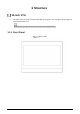
1 Structure 10-inch VTH The VTHs have the same front panel but differ in the ports in the rear panel. Some support 2wire and others does not. Slight differences might be found in the ports of the actual product. 1.1.
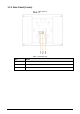
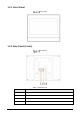
1.1.2 Rear Panel (2-wire) Rear panel Table 1-1 Components No.
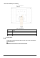
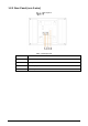
1.1.3 Rear Panel (non 2-wire) Rear panel Table 1-2 Components No. Name 1 Alarm port 2 Power input port 3 Network port 7-inch VTH The VTHs have the same front panel but differ in the ports in the rear panel. Some support 2wire and others does not. Slight differences might be found in the ports of the actual product.
1.2.1 Front Panel Front panel 1.2.2 Rear Panel (2-wire) Rear panel Table 1-3 Components No.
1.2.3 Rear Panel (non 2-wire) Rear panel Table 1-4 Components No.
2 Installation Preparations Do not install the VTH in harsh environment with condensation, high temperature, dust, corrosive substance and direct sunlight. In case of abnormality after powering on the VTH, cut off the power supply at once, and unplug the network cable. Power on after troubleshooting. Installation should be done by professional teams. Do not dismantle or repair the device by yourself in case of device failure. Contact after-sales service if you need any help.
3 VTH Configuration This chapter introduces the configuration of the VTH and digital outdoor station (hereinafter referred to as the “VTO”) to achieve the intercom function. Follow the instructions below to get started. Before You Begin Make sure that there is no short or open circuit in the VTO and VTH. Plan IP and number (working as a phone number) for each VTO and VTH. Make sure that the VTH and VTO are on the network segment.
Quick configuration Select First-time Config, and then tap OK. Config mode Select Static IP, enter your planned VTH IP, net mask and gateway, and then tap Next. On the Set VTH Password screen, enter and confirm the password, and enter the email address, and then tap Next.
Set password for VTH On the Set VTO Password screen, enter the password of VTO and confirm it, and then tap Next. Set password for VTO Tap Initialize to complete the initialization of the VTO and the main VTH, and then tap Next. You need to make sure that the IP addresses of the VTH and VTO on the same network segment. Otherwise, VTH cannot obtain the information of VTO after configuration.
Initialize the devices Tap One-key Config to finish the configuration of the VTO and VTH, as well as the SIP server. The status bar will suggest whether your configuration is successful. Configuring Network Parameters You can choose to connect to the network either through WLAN or LAN. 3.3.1 WLAN Tap and hold Setting for about 3 seconds, and enter the password that you set for the VTH. Tap Network > WLAN. Enable to see all the usable networks.
WLAN 3.3.2 LAN Tap and hold Setting for about 3 seconds, and enter the password that you set for the VTH. Tap Network > LAN. Enter local IP subnet mask and gateway that you plan for the VTH. You can also tap automatically. to enable the DHCP function to obtain IP information LAN Tap OK.
Configuring SIP Server Tap and hold Setting for about 3 seconds, and enter the password that you set for the VTH. Tap SIP Server. SIP server Configure the SIP server parameters. Set Enable Status to . Tap OK. Table 3-1 SIP server Parameter Description Server IP When the platform works as SIP server, server IP is the IP address of the platform. When VTO works as SIP server, server IP is the IP address of the VTO. Network Port When the platform works as SIP server, the network port is 5080.
Configuring VTH Tap and hold Setting for about 3 seconds, and enter the password that you set for the VTH. Tap VTH Config. VTH configuration Enter room number (such as 9901 or 101#0). If there is an extension VTH, room number must end with #0. Otherwise, it will fail to connect to VTO. Tap OK. Configuring VTO Tap and hold Setting for about 3 seconds, and enter the password that you set for the VTH. Tap VTO Config.
VTO configuration Add VTO. 3.6.2 Adding Main VTO Enter main VTO name, VTO IP address, username and password. Set Enable Status to . Check whether the configuration is successful by checking the status bar at the top right corner. 3.6.3 Adding Sub VTO Enter sub VTO name, sub VTO IP address, username, and password. Set Enable Status to . Check whether the configuration is successful by checking the status bar at the top right corner.
4 Commissioning After the basic configuration is complete, check whether the intercom function can work. VTO Calling VTH Dial a room number on the VTO (for example, 9901). Tap on the VTH to answer the call. Call VTH from VTO VTH Monitoring VTO A VTH can monitor VTO. On the home screen, select Monitor > Door. Set the VTO to go to the monitoring page. Tap the icon to view the VTO video. The following figure means that SD card has been inserted into VTH.
Door Monitoring device 16
Cybersecurity Recommendations Mandatory actions to be taken for basic device network security: 1. Use Strong Passwords Please refer to the following suggestions to set passwords: The length should not be less than 8 characters; Include at least two types of characters; character types include upper and lower case letters, numbers and symbols; Do not contain the account name or the account name in reverse order; Do not use continuous characters, such as 123, abc, etc.
8. 9. 10. 11. 12. 13. We recommend you to bind the IP and MAC address of the gateway to the device, thus reducing the risk of ARP spoofing. Assign Accounts and Privileges Reasonably According to business and management requirements, reasonably add users and assign a minimum set of permissions to them. Disable Unnecessary Services and Choose Secure Modes If not needed, it is recommended to turn off some services such as SNMP, SMTP, UPnP, etc., to reduce risks.