
Quick Guide
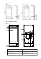
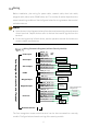
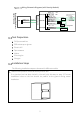
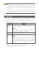
Table Of Contents

4
Wiring
Before installation, plan wiring for power cable, network cable, door lock cable,
wiegand cable, alarm cable, RS485 cable, etc. The number of cables depends on the
actual networking conditions. See the figures below for wiring between the terminal
and other devices.
N
OTE!
•
Input devices in the diagrams below refer to devices that send signals to the access
control terminal. Output devices refer to devices that receive signals from the
terminal.
•
For the wiring terminal of each device, see the operation
manual of the device or
consult related manufacturers.
Wiring Schematic Diagrams (without Security Module)
The face recognition access control terminal can be also connected to a security
module. The figure below shows the wiring of the security module.
Power input
Alarm input
Alarm output
RS485
Wiegand output
Wiegand input
Door lock
VDD12V
Red
GND
Black
+12V
GND
GND
Black
ALM_IN2
White/Purple
ALM_IN1
Purple
ALM_OUT_NO
White/Blue
ALM_OUT_NC
Gray
ALM_OUT_COM
White/Orange
RS485_A
Orange
RS485_B
Yellow
GND
Black
WIEGAND_IN0
Blue
WIEGAND_IN1
White
GND
Black
WIEGAND__OUT0
Brown
WIEGAND__OUT1
Green
LOCK_NC
Pink
LOCK_COM
White/Yellow
LOCK_NO
White/Green
GND
Black
SEN_ INPUT
Light Green
BUTTON_INPUT
Yellow/Black
PRESS
TO EXIT
+
+
-
-
+
-
Face Recognition Access Control Terminal
-
+
Network interface
Door opening button
Electric strike
Door magnetic
sensor
Power supply
Electric drop bolt lock
/Magnetic lock
Access
controller
Wiegand
card reader
Alarm output device
Alarm output device
Alarm input device
Alarm input device
Power
supply
Digital detection module